Table of Contents
Advertisement
Quick Links
CAN-USB/3-FD
USB 2.0 Module with CAN FD Interface
Hardware Manual
to Product C.2076.62
CAN-USB/3-FD
Hardware Manual Doc. Nr.: C.2076.23 / Rev 1.0
Page 1 of 31
esd electronics gmbh
Vahrenwalder Str. 207 • 30165 Hannover • Germany
http://www.esd.eu
Phone: +49 (0) 511 3 72 98-0 • Fax: +49 (0) 511 3 72 98-68
Advertisement
Table of Contents

Related Manuals for ESD CAN-USB/3-FD


Summary of Contents for ESD CAN-USB/3-FD
- Page 1 CAN-USB/3-FD Hardware Manual Doc. Nr.: C.2076.23 / Rev 1.0 Page 1 of 31 esd electronics gmbh Vahrenwalder Str. 207 • 30165 Hannover • Germany http://www.esd.eu Phone: +49 (0) 511 3 72 98-0 • Fax: +49 (0) 511 3 72 98-68...
- Page 2 design.
- Page 3 The changes in the document listed below affect changes in the hardware as well as changes in the description of the facts, only. Rev. Chapter Changes versus previous version Date First English manual of CAN-USB/3-FD 2021-12-02 Editorial changes only: Note on disposal revised 2022-09-05 Note on USB version revised 6., 7.
- Page 4 This NOTICE statement contains the general mandatory sign and gives information that must be heeded and complied with for a safe use. INFORMATION INFORMATION Notes to point out something important or useful. Hardware Manual Doc. Nr.: C.2076.23 / Rev. 1.0 Page 4 of 31 CAN-USB/3-FD...
-
Page 5: Safety Instructions
● When working with the CAN-USB/3-FD follow the instructions below and read the manual carefully to protect yourself from injury and the CAN-USB/3-FD from damage. ● Do not use damaged or defective cables to connect the CAN-USB/3-FD and follow the CAN wiring hints in chapter: "Correct Wiring of Electrically Isolated CAN Networks". - Page 6 The intended use of the CAN-USB/3-FD is the operation as an USB 2.0-CAN-Interface. The guarantee given by esd does not cover damages which result from improper use, usage not in accordance with regulations or disregard of safety instructions and warnings.
-
Page 7: Table Of Contents
Table of Contents Safety Instructions .......................... 5 1 Overview ............................ 9 1.1 Description of CAN-USB/3-FD ................... 9 1.2 Glossary ........................... 10 2 Case View with Connectors and LEDs ..................11 2.1 LED-Displays ........................12 3 Hardware Installation ........................ 13 4 Technical Data ......................... 14 4.1 General Technical Data .................... - Page 8 Table 4: Connectors, accessible from outside ................15 Table 5: Data of the CAN interface ....................15 Table 6: Recommended cable lengths at typical bit rates (with esd-CAN interfaces) ....25 Table 7: Order information hardware .................... 31 Table 8: Order information software for CAN-USB/3-FD-FD ............31 Table 9: Available Manuals ......................
-
Page 9: Overview
LEDs Figure 1: Block circuit diagram The CAN-USB/3-FD module is a USB to CAN FD-interface that uses an ARM® Cortex®-M7 based microcontroller. The module supports the USB 2.0 high-speed interface with data rates of 480 Mbit/s. The supply voltage is fed via the USB bus. -
Page 10: Glossary
Controller Area Network Flexible Data-Rate Central Processing Unit CAN in Automation DSUB9 D-subminiature electrical connector with 9 positions Hardware Input/Output n.a. not applicable Operating System Software Development Kit Universal Serial Bus Page 10 of 31 Hardware Manual Doc. Nr.: C.2076.23 / Rev. 1.0 CAN-USB/3-FD... -
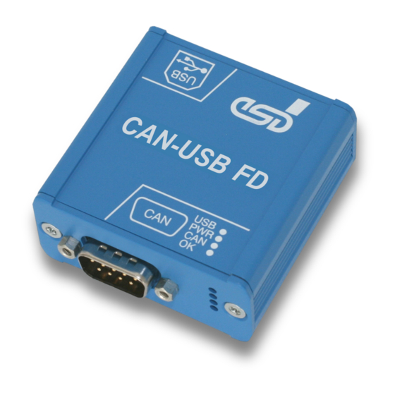
Page 11: Case View With Connectors And Leds
See also from page 18 for signal assignments of the CAN connector and the USB connector. NOTICE Read chapter “Hardware Installation” on page 13, before you start with the installation of the hardware! Hardware Manual Doc. Nr.: C.2076.23 / Rev. 1.0 CAN-USB/3-FD Page 11 of 31... -
Page 12: Led-Displays
CAN interface is initialized and in mode “Automatic Baud rate slow flashing Detection” (from firmware version 1.0.0.4 and CAN driver version (approx. 1 Hz) 2.5.2 on) Table 1: Description of LEDs Page 12 of 31 Hardware Manual Doc. Nr.: C.2076.23 / Rev. 1.0 CAN-USB/3-FD... -
Page 13: Hardware Installation
Carefully read the safety instructions at the beginning of this document before you start with the hardware installation! Connect the CAN bus via the DSUB9 connector of the CAN-USB/3-FD as described in chapter “Correctly Wiring Electrically Isolated CAN Networks”. Please note that the CAN bus must be terminated at both ends! esd offers special T-connectors and termination connectors for external termination. -
Page 14: Technical Data
USB interface USB Specification Rev. 2.0, bit rate 480 Mbit/s, USB controller integrated in CPU ARM Cortex-M7 (ATSAME70N20), 32-bit 300 MHz Table 3: USB interface and microcontroller Page 14 of 31 Hardware Manual Doc. Nr.: C.2076.23 / Rev. 1.0 CAN-USB/3-FD... -
Page 15: Connectors Accessible From Outside
CAN to Host/System Ground;): 1kV DC @ 1s (I < 1 mA) Bus termination Terminating resistor has to be set externally, if required Table 5: Data of the CAN interface Hardware Manual Doc. Nr.: C.2076.23 / Rev. 1.0 CAN-USB/3-FD Page 15 of 31... -
Page 16: Software Support
- 40 MB free HD drive space - esd CAN driver installed The CAN Tools are included in the CAN-CD as part of the esd Software Development Kit (CAN SDK) of the NTCAN-API. The CAN SDK can also be downloaded free-of-charge from the esd website. -
Page 17: License
4.6 License The CAN-USB/3-FD uses the opensource FreeRTOS operating system. For the full license text please see esd's "3rd Party Licensor Notice"-document, that is part of the product's documentation on the enclosed CD. Hardware Manual Doc. Nr.: C.2076.23 / Rev. 1.0... -
Page 18: Connector Assignments
CAN_GND reference potential of the local CAN physical layer Shield shielding (connected with the case of the 9-pin DSUB connector and with the case of CAN-USB/3-FD) Reserved reserved for future applications, do not connect! Page 18 of 31 Hardware Manual Doc. Nr.: C.2076.23 / Rev. 1.0... -
Page 19: Usb Socket
Shielding (connected with the case of the USB connector and with the case of the CAN-USB/3-FD) NOTICE As USB 2.0 device, the CAN-USB/3-FD can be connected to USB ports that comply with USB standards at least from USB 1.1! Please note that at least USB 2.0 is required for USB high-speed operation. -
Page 20: Correct Wiring Of Electrically Isolated Can Networks
Therefore, the maximum achievable number of nodes, bus lengths and stub lengths may differ from the theoretically possible number! esd has limited its recommendations for CAN wiring to the specifications of ISO 11898-2. A description of the special features of the derived specifications CANopen, ARINC825, DeviceNet,... -
Page 21: Light Industrial Environment (Single Twisted Pair Cable)
6.2.1 General Rules NOTICE esd grants the EU Conformity of the product if the CAN wiring is carried out with at least single shielded single twisted pair cables that match the requirements of ISO 11898-2. Single shielded double twisted pair cable wiring as described in chapter 6.3 ensures the EU Conformity as well. -
Page 22: Cabling
In principle the CAN bus must be realized in a line. The nodes are connected to the main • CAN bus line via short cable stubs. This is normally realised by so called T-connectors. esd offers the CAN-T-Connector (Order No.: C.1311.03) If a mixed application of single twisted and double twisted cables cannot be avoided, •... -
Page 23: Heavy Industrial Environment (Double Twisted Pair Cable)
6 Select a working combination of bit rate and cable length. 7 Keep away CAN cables from disturbing sources. If this cannot be avoided, double shielded cables are recommended. Figure 6: CAN wiring for heavy industrial environment Hardware Manual Doc. Nr.: C.2076.23 / Rev. 1.0 CAN-USB/3-FD Page 23 of 31... -
Page 24: Device Cabling
CAN bus line via short cable stubs. This is usually realised via so called T-connectors. When using esd's CAN-T-Connector (order no.: C.1311.03) in heavy industrial environment and with four-wire twisted cables, it must be noted that the shield potential of the conductive DSUB housing is not looped through this type of T-connector. -
Page 25: Electrical Grounding
Table 6: Recommended cable lengths at typical bit rates (with esd-CAN interfaces) Optical couplers are delaying the CAN signals. esd modules typically achieve a wire length of 37 m at 1 Mbit/s within a proper terminated CAN network without impedance disturbances, such as those caused by cable stubs >... -
Page 26: Examples For Can Cables
CiA 106: “Connector pin-assignment recommendations ”. 6.6 Examples for CAN Cables esd recommends the following two-wire and four-wire cable types for CAN network design. These cable types are used by esd for ready-made CAN cables, too. -
Page 27: Can Troubleshooting Guide
• All CAN_H and CAN_L lines are correctly connected. • Two terminating resistors of 120 Ω each are connected to your CAN network (one at each end). Hardware Manual Doc. Nr.: C.2076.23 / Rev. 1.0 CAN-USB/3-FD Page 27 of 31... -
Page 28: Electrical Grounding
Measure the DC voltage between CAN_L and CAN_GND, measuring point (See “Simplified diagram of a CAN network” on previous page). Expected result: The measured voltage should be between 2.0 V and 3.0 V. Page 28 of 31 Hardware Manual Doc. Nr.: C.2076.23 / Rev. 1.0 CAN-USB/3-FD... -
Page 29: Can Transceiver Resistance Test
Another indication of a defective CAN transceiver is a very high deviation of the two measured input resistances (>> 200 %). 7.6 Support by esd If you have followed the troubleshooting steps in this troubleshooting guide and still cannot find a solution to your problem, our support team can help. -
Page 30: Declaration Of Conformity
Declaration of Conformity 8 Declaration of Conformity Page 30 of 31 Hardware Manual Doc. Nr.: C.2076.23 / Rev. 1.0 CAN-USB/3-FD... -
Page 31: Order Information
Table 9: Available Manuals Printed Manuals If you need a printout of the manual additionally, please contact our sales team (sales@esd.eu) for a quotation. Printed manuals may be ordered for a fee. Hardware Manual Doc. Nr.: C.2076.23 / Rev. 1.0...
Need help?
Do you have a question about the CAN-USB/3-FD and is the answer not in the manual?
Questions and answers