Table of Contents
Advertisement
Quick Links
CAN-PC104/200
Passive CAN-PC104-CAN Interface
Hardware Installation
and
Technical Data
to Product C.2013.04
CAN-PC104/200
Hardware Manual • Doc. No.: C.2013.21 / Rev. 1.7
Page 1 of 31
esd electronic system design gmbh
Vahrenwalder Str. 207 • 30165 Hannover • Germany
http://www.esd.eu
Phone: +49 (0) 511 3 72 98-0 • Fax: +49 (0) 511 3 72 98-68
Advertisement
Table of Contents

Related Manuals for ESD CAN-PC104/200


Summary of Contents for ESD CAN-PC104/200
- Page 1 CAN-PC104/200 Hardware Manual • Doc. No.: C.2013.21 / Rev. 1.7 Page 1 of 31 esd electronic system design gmbh Vahrenwalder Str. 207 • 30165 Hannover • Germany http://www.esd.eu Phone: +49 (0) 511 3 72 98-0 • Fax: +49 (0) 511 3 72 98-68...
- Page 2 The information in this document has been carefully checked and is believed to be entirely reliable. esd makes no warranty of any kind with regard to the material in this document, and assumes no responsibility for any errors that may appear in this document. In particular descriptions and technical data specified in this document may not be constituted to be guaranteed product features in any legal sense.
- Page 3 Date of print: 2015-12-07 Document type DOC0800 number: Hardware version: CAN-PC104/200 Rev. 1.2 (SJA1000) Document History The changes in the document listed below affect changes in the hardware as well as changes in the description of the facts, only. Rev. Chapter...
- Page 4 This NOTICE statement contains the general mandatory sign and gives information that must be heeded and complied with for a safe use. INFORMATION INFORMATION Notes to point out something important or useful. Page 4 of 31 Hardware Manual • Doc. No.: C.2013.21 / Rev. 1.7 CAN-PC104/200...
-
Page 5: Safety Instructions
● The device is a built-in component. It is essential to ensure that the device is mounted in a way that cannot lead to endangering or injury of persons or damage to objects. ● Do not use damaged or defective cables to connect the CAN-PC104/200 and follow the CAN wiring hints in chapter: "Correct Wiring of Electrically Isolated CAN Networks". - Page 6 Service Note The CAN-PC104/200 does not contain any parts that require maintenance by the user. The CAN- PC104/200 does not require any manual configuration of the hardware. Unauthorized intervention in the device voids warranty claims. Disposal Devices which have become defective in the long run have to be disposed in an appropriate way or have to be returned to the manufacturer for proper disposal.
-
Page 7: Table Of Contents
CAN Troubleshooting Guide.......................28 7.1 Termination.......................... 28 Electrical Grounding......................29 Short Circuit in CAN Wiring....................29 CAN_H/CAN_L-Voltage ......................29 CAN Transceiver Resistance Test..................30 Support by esd........................30 Order Information........................31 CAN-PC104/200 Hardware Manual • Doc. No.: C.2013.21 / Rev. 1.7 Page 7 of 31... -
Page 8: Overview
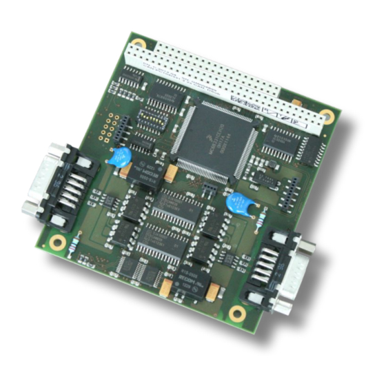
PC/104 Connector Figure 1: Block circuit diagram of CAN-PC104/200 The CAN-PC104/200 board is a CAN-module for the PC/104-bus (PC/104, 8 bit). It uses a SJA1000 CAN controller. The module can be operated in FULL- or BASIC-CAN. The CAN-interface is ISO11898-compliant and allows a maximum data-transfer rate of 1 Mbit/s. -
Page 9: Pcb View With Connectors
Read chapter “Hardware Installation” on page 11, before you start with the installation of the hardware! See also page 20 for signal assignment of the connectors. CAN-PC104/200 Hardware Manual • Doc. No.: C.2013.21 / Rev. 1.7 Page 9 of 31... -
Page 10: Connector Position And Board Dimensions
Overview 1.2 Connector Position and Board Dimensions 96,0 86,0 55,0 DSUB 9 All listed values are in millimetres. Figure 3: CAN-PC104/200 technical drawing Page 10 of 31 Hardware Manual • Doc. No.: C.2013.21 / Rev. 1.7 CAN-PC104/200... -
Page 11: Hardware Installation
I/O Port. A list with the used and available address ranges appears. Make sure that the default value of the CAN-PC104/200 is in a free memory area. If it is not, note one free memory area (which corresponds to the choices stated in Figure 4 on page 13) and change the CAN-PC104/200 address by means of the jumper field during the hardware installation described below. -
Page 12: Installing The Hardware And Setting The Pc/104-Bus Address
Hardware Installation 2.2 Installing the Hardware and Setting the PC/104-Bus Address The CAN-PC104/200 module can be used in all PC/104-compatible systems (e.g. portable industry PCs or fixed control plants). The carrier system will therefore be described by the general term ‘computer’... - Page 13 If you are working with Windows 9x/ME, you have to set the jumpers as proposed by the Windows-Hardware Wizard. Install the CAN module at the selected PC/104-stack position. Close the computer case. CAN-PC104/200 Hardware Manual • Doc. No.: C.2013.21 / Rev. 1.7 Page 13 of 31...
- Page 14 Additionally, the CAN_GND must be connected to earth at exactly one point in the CAN network. Use the special T- connectors and terminator connectors offered by esd. A CAN device whose CAN interface is not electrically isolated acts as an earth connection like the CAN_GND.
-
Page 15: Accessing The Controllers
This chapter describes the addresses and registers of the CAN-controller on the board. The information given here is only important for programmers who do not use the driver software available from esd for the module! 3.2 Address Range The address range for the access to individual controller is eight bytes. The basis address can be set by means of jumpers. -
Page 16: Setting The Board Interrupt
By means of Selection nibble one from ten IRQs within the PC104 PC can be selected: free free free free free free Table 2: Selecting the interrupt Page 16 of 31 Hardware Manual • Doc. No.: C.2013.21 / Rev. 1.7 CAN-PC104/200... -
Page 17: Examples
Deactivate IRQ : = level; (delete selection completely) for (i=0;i<4;i++) outp(canIoPort+3,0x07); stat=i; outp(canIoPort+3,0x06); if (i1 & 0x01) for (i=0;i<4;i++) stat |= 0x80; outp(canIoPort+3,i); outp(canIoPort+3,stat); i1=i1>>1; outp(canIoPort+3,0x87); outp(canIoPort+3,0x86); CAN-PC104/200 Hardware Manual • Doc. No.: C.2013.21 / Rev. 1.7 Page 17 of 31... -
Page 18: Technical Data
4.2 PC/104 Bus Host bus PC/104 PC/104-data bus 8 bit Interrupt 1 out of 12 Connectors PC/104 PCB connectors, 40-pole and 64-pole Table 4: PC/104 bus data Page 18 of 31 Hardware Manual • Doc. No.: C.2013.21 / Rev. 1.7 CAN-PC104/200... -
Page 19: Can Interface
(sales@esd.eu). INFORMATION The CAN layer 2 (NTCAN-API) software installation and the software drivers are described in the NTCAN-API manual (esd-order No.: C.2001.21): “NTCAN-API Part 1: Application Developers manual” and “NTCAN-API Part 2: Installation Guide” A few basic C-program codes are contained for initialization, setting the bit rate and for CAN-read and write accesses. -
Page 20: Connector Pin Assignment
CAN physical layer Shield ... shielding (connected with the case of the 9-pin DSUB connector) reserved ... reserved for future applications, do not connect! Page 20 of 31 Hardware Manual • Doc. No.: C.2013.21 / Rev. 1.7 CAN-PC104/200... -
Page 21: Correct Wiring Of Electrically Isolated Can Networks
Therefore the practical maximum number of nodes, bus length and stub length are typically much lower. esd has concentrated her recommendations concerning CAN wiring on the specifications of the ISO 11898-2. Thus this wiring hints forgoes to describe the special features of the derived standards CANopen, ARINC825, DeviceNet and NMEA2000. -
Page 22: Light Industrial Environment (Single Twisted Pair Cable)
CAN_H n.c. n.c. CAN_GND n.c. n.c. n.c. n.c. connector case connector case n.c. = not connected earth (FE) Figure 5: CAN wiring for light industrial environment Page 22 of 31 Hardware Manual • Doc. No.: C.2013.21 / Rev. 1.7 CAN-PC104/200... -
Page 23: Cabling
9-pin DSUB-termination connectors with integrated termination resistor and male and ● female contacts (gender changer) are available from esd (order no. C.1303.01). DSUB termination connectors with male contacts (order no. C.1302.01) or female contacts ● (order no. C.1301.01) and additional functional earth contact are available, if CAN termination and grounding of CAN_GND is required. -
Page 24: Heavy Industrial Environment (Double Twisted Pair Cable)
CAN_L CAN_GND wire shield n.c. n.c. connector case connector case Shield n.c. = not connected earth (FE) Figure 7: CAN wiring for heavy industrial environment Page 24 of 31 Hardware Manual • Doc. No.: C.2013.21 / Rev. 1.7 CAN-PC104/200... -
Page 25: Device Cabling
DSUB9 connector from ERNI (ERBIC CAN BUS MAX, order no.:154039). The usage of esd’s T-connector type C.1311.03 is not recommended for single shielded double twisted pair cables because the shield potential of the conductive DSUB housing is not looped through this T-connector type. -
Page 26: Electrical Grounding
5000 Table 6: Recommended cable lengths at typical bit rates (with esd-CAN interfaces) Optical couplers are delaying the CAN signals. esd modules typically reach a wire length of ● 37 m at 1 Mbit/s within a proper terminated CAN network without impedance disturbances like e.g. -
Page 27: Examples For Can Cables
Correct Wiring of Electrically Isolated CAN Networks 6.6 Examples for CAN Cables esd recommends the following two-wire and four-wire cable types for CAN network design. These cable types are used by esd for ready-made CAN cables, too. 6.6.1 Cable for light industrial Environment Applications (Two-Wire) -
Page 28: Can Troubleshooting Guide
- there are no open circuits in CAN_H or CAN_L wiring - your bus system has two terminating resistors (one at each end) and that they are 120 Ω each. Page 28 of 31 Hardware Manual • Doc. No.: C.2013.21 / Rev. 1.7 CAN-PC104/200... -
Page 29: Electrical Grounding
(see figure at previous page). 4. Measure the DC voltage between CAN_L and CAN_GND (see figure at previous page). Normally the voltage should be between 2.0 V and 3.0 V. CAN-PC104/200 Hardware Manual • Doc. No.: C.2013.21 / Rev. 1.7 Page 29 of 31... -
Page 30: Can Transceiver Resistance Test
If you have executed the fault diagnostic steps of this troubleshooting guide and you even can not find a solution for your problem our support department will be able to assist. Please contact our support via email at support@esd.eu or by phone +40-511-37298-130. Page 30 of 31 Hardware Manual •... -
Page 31: Order Information
For detailed information about the driver availability for your operating system, please contact our sales team. PDF Manuals Manuals are available in English and usually in German as well. For availability of English manuals see table below. Please download the manuals as PDF documents from our esd website www.esd.eu for free. Manuals Order No.
Need help?
Do you have a question about the CAN-PC104/200 and is the answer not in the manual?
Questions and answers