Table of Contents
Advertisement
Quick Links
CAN-ISA/331
1 or 2 Channel ISA-CAN Interface
®
(Layer 2, CANopen
or J1939)
Hardware Manual
to Products
C.2010.02 (1x CAN)
C.2010.04 (2x CAN)
CAN-ISA/331
Hardware Manual • Doc. No.: C.2010.21 / Rev. 1.7
Page 1 of 27
esd electronic system design gmbh
Vahrenwalder Str. 207 • 30165 Hannover • Germany
http://www.esd.eu
Phone: +49 (0) 511 3 72 98-0 • Fax: +49 (0) 511 3 72 98-68
Advertisement
Table of Contents

Related Manuals for ESD CAN-ISA/331


Summary of Contents for ESD CAN-ISA/331
- Page 1 CAN-ISA/331 Hardware Manual • Doc. No.: C.2010.21 / Rev. 1.7 Page 1 of 27 esd electronic system design gmbh Vahrenwalder Str. 207 • 30165 Hannover • Germany http://www.esd.eu Phone: +49 (0) 511 3 72 98-0 • Fax: +49 (0) 511 3 72 98-68...
- Page 2 The information in this document has been carefully checked and is believed to be entirely reliable. esd makes no warranty of any kind with regard to the material in this document, and assumes no responsibility for any errors that may appear in this document. In particular descriptions and technical data specified in this document may not be constituted to be guaranteed product features in any legal sense.
- Page 3 Date of print: 2015-12-07 Document type DOC0800 number: Hardware version: CAN-ISA/331 Rev. 1.0 CAN-ISA/331 Rev. 1.1 Document History The changes in the document listed below affect changes in the hardware as well as changes in the description of the facts, only.
- Page 4 This NOTICE statement contains the general mandatory sign and gives information that must be heeded and complied with for a safe use. INFORMATION INFORMATION Notes to point out something important or useful. Page 4 of 27 Hardware Manual • Doc. No.: C.2010.21 / Rev. 1.7 CAN-ISA/331...
-
Page 5: Safety Instructions
● The device is a built-in component. It is essential to ensure that the device is mounted in a way that cannot lead to endangering or injury of persons or damage to objects. ● Do not use damaged or defective cables to connect the CAN-ISA/331 and follow the CAN wiring hints in chapter: "Correct Wiring of Electrically Isolated CAN Networks". - Page 6 Safety Instructions Intended Use The intended use of the CAN-ISA/331 is the operation as an ISA-CAN interface board for PCs. The guarantee given by esd does not cover damages which result from improper use, usage not in accordance with regulations or disregard of safety instructions and warnings.
-
Page 7: Table Of Contents
7.1 Termination.......................... 23 Electrical Grounding......................24 Short Circuit in CAN Wiring....................24 CAN_H/CAN_L-Voltage ......................24 CAN Transceiver Resistance Test..................25 Support by esd........................25 Declaration of Conformity......................26 Order Information........................27 CAN-ISA/331 Hardware Manual • Doc. No.: C.2010.21 / Rev. 1.7 Page 7 of 27... -
Page 8: Overview
+5 V= Figure 1: Block circuit diagram The module CAN-ISA/331 is a PC board designed for the ISA bus (ISA 16 bit) with electrically isolated high-speed CAN interfaces. It uses a 68331 micro controller, which cares for the local CAN data management. -
Page 9: Pcb View With Position Of Jumper And Connectors
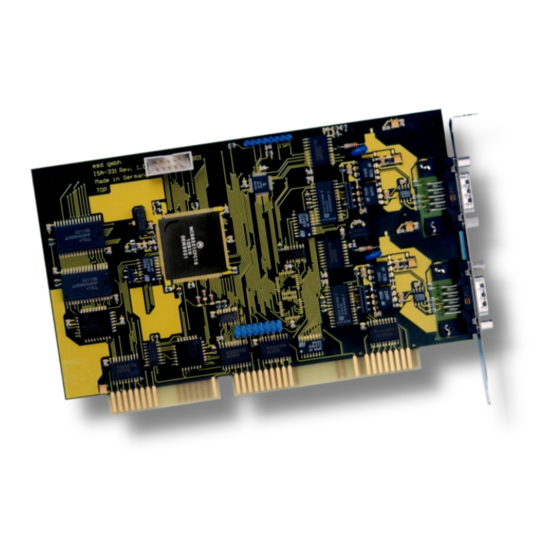
2. PCB View with Position of Jumper and Connectors Figure 2: PCB top view NOTICE Read chapter “3.1 Before Starting Hardware Installation” on page 10, before you start with the installation of the hardware! CAN-ISA/331 Hardware Manual • Doc. No.: C.2010.21 / Rev. 1.7 Page 9 of 27... -
Page 10: Hardware Installation
ISA I/O port address of the board. The address is default factory set to 1E0...1E7 HEX at the jumper field JP100. The CAN-ISA/331 covers 8 data bytes. Make sure, that there will be no address conflict with other ISA boards in the PC and... -
Page 11: Procedure
0x390 - 0x397 HEX Default Setting jumper inserted jumper not inserted Figure 4: Default jumper setting and settings that are supported by the Windows NT installation program CAN-ISA/331 Hardware Manual • Doc. No.: C.2010.21 / Rev. 1.7 Page 11 of 27... - Page 12 Windows 95 hardware assistant. For the installing instructions of other operating system drivers please refer the manual ‘NTCAN-API, Installation Guide’. Insert the CAN-ISA/331 board into the selected ISA slot. Carefully push the board down until it snaps into place. Attach the board.
-
Page 13: Technical Data
CAN board on the ISA bus Board dimension 'short' ISA board Connector ISA card edge connector Table 2: ISA Bus Interface CAN-ISA/331 Hardware Manual • Doc. No.: C.2010.21 / Rev. 1.7 Page 13 of 27... -
Page 14: Can Interface
“NTCAN-API Part 1: Structure, Function and C/C++ API” Application Developers Manual and “NTCAN-API Part 2: Installation, Configuration and Firmware Update” Installation Guide esd-order No.: C.2001.21 Page 14 of 27 Hardware Manual • Doc. No.: C.2010.21 / Rev. 1.7 CAN-ISA/331... -
Page 15: Connector Assignments
CAN physical layer Shield ... shielding (connected with the case of the 9-pin DSUB connector) reserved ... reserved for future applications, do not connect! CAN-ISA/331 Hardware Manual • Doc. No.: C.2010.21 / Rev. 1.7 Page 15 of 27... -
Page 16: Correct Wiring Of Electrically Isolated Can Networks
Therefore the practical maximum number of nodes, bus length and stub length are typically much lower. esd has concentrated her recommendations concerning CAN wiring on the specifications of the ISO 11898-2. Thus this wiring hints forgoes to describe the special features of the derived standards CANopen, ARINC825, DeviceNet and NMEA2000. -
Page 17: Heavy Industrial Environment (Double Twisted Pair Cable)
6.2.1 General Rules NOTICE esd only grants the compliance with directive 2014/30/EU, if the CAN wiring is carried out with single shielded double twisted pair cables that match the requirements of ISO 11898- The following general rules for the CAN wiring with single shielded double twisted pair cable should be followed: A cable type with a wave impedance of about 120 Ω... -
Page 18: Device Cabling
DSUB9 connector from ERNI (ERBIC CAN BUS MAX, order no.:154039). The usage of esd’s T-connector type C.1311.03 is not recommended for single shielded double twisted pair cables because the shield potential of the conductive DSUB housing is not looped through this T-connector type. -
Page 19: Light Industrial Environment (Single Twisted Pair Cable)
6.3.1 General Rules NOTICE esd only grants the compliance with directive 2014/30/EU, if the CAN wiring is carried out with single shielded double twisted pair cables that match the requirements of ISO 11898- 2. See previous chapter: 'Heavy Industrial Environment (Double Twisted Pair Cable)'. -
Page 20: Cabling
9-pin DSUB-termination connectors with integrated termination resistor and male and ● female contacts (gender changer) are available from esd (order no. C.1303.01). DSUB termination connectors with male contacts (order no. C.1302.01) or female contacts ● (order no. C.1301.01) and additional functional earth contact are available, if CAN termination and grounding of CAN_GND is required. -
Page 21: Electrical Grounding
5000 Table 4: Recommended cable lengths at typical bit rates (with esd-CAN interfaces) Optical couplers are delaying the CAN signals. esd modules typically reach a wire length of ● 37 m at 1 Mbit/s within a proper terminated CAN network without impedance disturbances like e.g. -
Page 22: Examples For Can Cables
Correct Wiring of Electrically Isolated CAN Networks 6.6 Examples for CAN Cables esd recommends the following two-wire and four-wire cable types for CAN network design. These cable types are used by esd for ready-made CAN cables, too. 6.6.1 Cable for light industrial Environment Applications (Two-Wire) -
Page 23: Can Troubleshooting Guide
- there are no open circuits in CAN_H or CAN_L wiring - your bus system has two terminating resistors (one at each end) and that they are 120 Ω each. CAN-ISA/331 Hardware Manual • Doc. No.: C.2010.21 / Rev. 1.7 Page 23 of 27... -
Page 24: Electrical Grounding
(see figure at previous page). 4. Measure the DC voltage between CAN_L and CAN_GND (see figure at previous page). Normally the voltage should be between 2.0 V and 3.0 V. Page 24 of 27 Hardware Manual • Doc. No.: C.2010.21 / Rev. 1.7 CAN-ISA/331... -
Page 25: Can Transceiver Resistance Test
If you have executed the fault diagnostic steps of this troubleshooting guide and you even can not find a solution for your problem our support department will be able to assist. Please contact our support via email at support@esd.eu or by phone +40-511-37298-130. CAN-ISA/331 Hardware Manual •... -
Page 26: Declaration Of Conformity
Declaration of Conformity 8. Declaration of Conformity Page 26 of 27 Hardware Manual • Doc. No.: C.2010.21 / Rev. 1.7 CAN-ISA/331... -
Page 27: Order Information
1x CAN 2.0A/B, ISO 11898 C.2010.02 CAN-ISA/331-2 2x CAN 2.0A/B, ISO 11898 C.2010.04 Each CAN-ISA/331 type includes a CD-ROM with CAN layer 2 software driver for Windows and Linux, demo programs and tools as well as documentation and manuals. Software CAN-DRV-LCD CDROM+Lizenz QNX object licence and CD-ROM for QNX 4.x and 6.x...
Need help?
Do you have a question about the CAN-ISA/331 and is the answer not in the manual?
Questions and answers