Table of Contents
Advertisement
Quick Links
CAN-USB/3-FD
USB 2.0 Module with CAN FD Interface
Hardware Manual
to Product C.2076.62,
C.2076.63
CAN-USB/3-FD
Hardware Manual Doc. Nr.: C.2076.23 / Rev 1.3
Page 1 of 31
esd electronics gmbh
Vahrenwalder Str. 207 • 30165 Hannover • Germany
http://www.esd.eu
Phone: +49 (0) 511 3 72 98-0 • Fax: +49 (0) 511 3 72 98-68
Advertisement
Table of Contents

Related Manuals for ESD C.2076.63


Summary of Contents for ESD C.2076.63
- Page 1 CAN-USB/3-FD Hardware Manual Doc. Nr.: C.2076.23 / Rev 1.3 Page 1 of 31 esd electronics gmbh Vahrenwalder Str. 207 • 30165 Hannover • Germany http://www.esd.eu Phone: +49 (0) 511 3 72 98-0 • Fax: +49 (0) 511 3 72 98-68...
- Page 2 design.
- Page 3 Document Information Document file: I:\Texte\Doku\MANUALS\CAN\CAN-USB-3-FD\Englisch\CAN-USB3-FD_Hardware-Manual_en_13.docx Date of print: 2023-02-24 Document-type DOC0800 number: Document History The changes in the document listed below affect changes in the hardware as well as changes in the description of the facts, only. Rev. Chapter Changes versus previous version Date First English manual of CAN-USB/3-FD 2021-12-02...
- Page 4 Classification of Warning Messages and Safety Instructions This manual contains noticeable descriptions, warning messages and safety instructions, which you must follow to avoid personal injuries or death and property damage. This is the safety alert symbol. It is used to alert you to potential personal injury hazards. Obey all safety messages and instructions that follow this symbol to avoid possible injury or death.
-
Page 5: Safety Instructions
It is the responsibility of the device's user to take care that necessary safety precautions for the... - Page 6 The intended use of the CAN-USB/3-FD is the operation as an USB 2.0-CAN-Interface. The guarantee given by esd does not cover damages which result from improper use, usage not in accordance with regulations or disregard of safety instructions and warnings.
-
Page 7: Table Of Contents
7.3 Short Circuit in CAN Wiring ....................28 7.4 Correct Voltage Levels on CAN_H and CAN_L ..............28 7.5 CAN Transceiver Resistance Test..................29 7.6 Support by esd ......................... 29 8 Declaration of Conformity ......................30 9 Order Information ........................31 9.1 Hardware ......................... - Page 8 Table 4: Connectors, accessible from outside ................15 Table 5: Data of the CAN interface ....................15 Table 6: Recommended cable lengths at typical bit rates (with esd-CAN interfaces) ....25 Table 7: Order information hardware .................... 31 Table 8: Order information software for CAN-USB/3-FD-FD ............31 Table 9: Available Manuals ......................
-
Page 9: Overview
Overview 1 Overview 1.1 About this Manual In this manual all variants of the module, the CAN-USB/3-FD and the CAN-USB/3-FD-DINrail, are described together as CAN-USB/3-FD. The hardware of the two variants is identical, except of the additional mounting rail holder equipped on the CAN-USB/3-FD-DINrail. Differences of the module variants are noted accordingly. -
Page 10: Glossary
Overview 1.3 Glossary Abbreviations Abbreviation Term Application Programming Interface Controller Area Network CAN FD Controller Area Network Flexible Data-Rate Central Processing Unit CAN in Automation DSUB9 D-subminiature electrical connector with 9 positions Hardware Input/Output n.a. not applicable Operating System Software Development Kit Universal Serial Bus Page 10 of 31 Hardware Manual Doc. -
Page 11: Module Views, Connectors And Leds
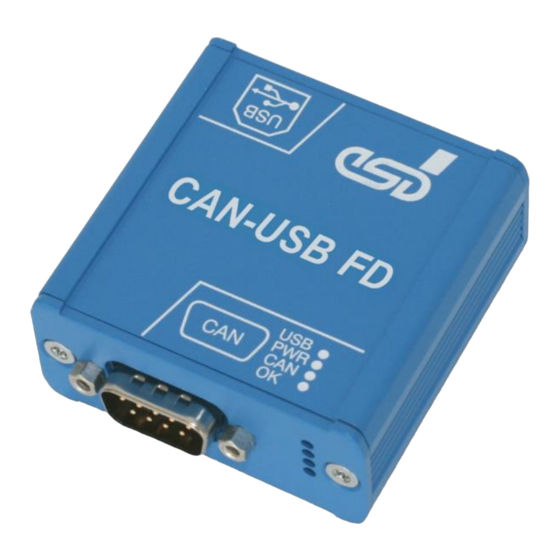
Module Views, Connectors and LEDs 2 Module Views, Connectors and LEDs 2.1 Module View USB Interface CAN FD Interface Figure 2: CAN-USB/3-FD front view NOTICE Read chapter “Hardware Installation” on page 13, before you start with the installation of the hardware! See also from page 18 for signal assignments of the CAN connector and the USB connector. -
Page 12: Top View With Usb Interface
Module Views, Connectors and LEDs 2.2 Top View with USB Interface Figure 4: Module top view with USB Interface 2.3 Bottom View with CAN Connector and LEDs Figure 5: Module view with CAN connector and LEDs 2.4 LED Description Description (See Figure 5 for the position of the LEDs) NAME Status... -
Page 13: Hardware Installation
“Correctly Wiring Electrically Isolated CAN Networks”. Please note that the CAN bus must be terminated at both ends! esd offers special T-connectors and termination connectors for external termination. Additionally, the CAN_GND signal must be connected to earth at exactly one point in the CAN network. -
Page 14: Technical Data
Technical Data 4 Technical Data 4.1 General Technical Data Power supply voltage Via USB 2.0 bus, Nominal voltage: 5V Current consumption: max. 250 mA Temperature range 0°C ... +50 °C ambient temperature Humidity Max. 90%, non-condensing Protection class IP20 Housing Tube case, Aluminium continuous casting Form factor / 55 mm x 54 mm x 25 mm... -
Page 15: Connectors Accessible From Outside
Technical Data 4.3 Connectors accessible from Outside Function, Name Type Interfaces CAN FD interfaces DSUB9 connector, pin contacts (X1) USB 2.0 interface USB socket, type B (X2), high retention force Table 4: Connectors, accessible from outside 4.4 CAN FD Interface Number of CAN FD interfaces 1 CAN controller Integrated in ATSAME70N20 CPU... -
Page 16: Software Support
- 40 MB free HD drive space - esd CAN driver installed The CAN Tools are included in the CAN-CD as part of the esd Software Development Kit (CAN SDK) of the NTCAN-API. The CAN SDK can also be downloaded free-of-charge from the esd website. -
Page 17: License
4.6 License The CAN-USB/3-FD uses the opensource FreeRTOS operating system. For the full license text please see esd's "3rd Party Licensor Notice"-document, that is part of the product's documentation on the enclosed CD. Hardware Manual Doc. Nr.: C.2076.23 / Rev. 1.3... -
Page 18: Connector Assignments
Connector Assignments 5 Connector Assignments 5.1 CAN (DSUB9) Device connector: 9-pin DSUB connector, pin contacts ® Connector pin-assignment according to CiA 106 recommendations. Pin Position: Pin Assignment: Signal Signal Reserved CAN_GND CAN_L CAN_H CAN_GND Reserved Reserved Reserved Shield Signal Description: CAN_L, CAN_H …... -
Page 19: Usb Socket
Connector Assignments 5.2 USB Socket Device connector: USB receptacle, standard type-B, high retention force Pin Position: Pin Assignment: Signal Shield Signal Description: VBUS ... +5 V power supply voltage D+, D-... USB signal lines Data+, Data- GND... Reference potential Shield Shielding (connected with the case of the USB connector and with the case of the CAN-USB/3-FD) NOTICE... -
Page 20: Correct Wiring Of Electrically Isolated Can Networks
Therefore, the maximum achievable number of nodes, bus lengths and stub lengths may differ from the theoretically possible number! esd has limited its recommendations for CAN wiring to the specifications of ISO 11898-2. A description of the special features of the derived specifications CANopen, ARINC825, DeviceNet,... -
Page 21: Light Industrial Environment (Single Twisted Pair Cable)
6.2.1 General Rules NOTICE esd grants the EU Conformity of the product if the CAN wiring is carried out with at least single shielded single twisted pair cables that match the requirements of ISO 11898-2. Single shielded double twisted pair cable wiring as described in chapter 6.3 ensures the EU Conformity as well. -
Page 22: Cabling
In principle the CAN bus must be realized in a line. The nodes are connected to the main • CAN bus line via short cable stubs. This is normally realised by so called T-connectors. esd offers the CAN-T-Connector (Order No.: C.1311.03) If a mixed application of single twisted and double twisted cables cannot be avoided, •... -
Page 23: Heavy Industrial Environment (Double Twisted Pair Cable)
Correct Wiring of Electrically Isolated CAN Networks 6.3 Heavy Industrial Environment (Double Twisted Pair Cable) 6.3.1 General Rules The following general rules for the CAN wiring with single shielded double twisted pair cable should be followed: 1 A suitable cable type with a wave impedance of about 120 Ω ±10% with an adequate conductor cross-section (≥... -
Page 24: Device Cabling
CAN bus line via short cable stubs. This is usually realised via so called T-connectors. When using esd's CAN-T-Connector (order no.: C.1311.03) in heavy industrial environment and with four-wire twisted cables, it must be noted that the shield potential of the conductive DSUB housing is not looped through this type of T-connector. -
Page 25: Electrical Grounding
Table 6: Recommended cable lengths at typical bit rates (with esd-CAN interfaces) Optical couplers are delaying the CAN signals. esd modules typically achieve a wire length of 37 m at 1 Mbit/s within a proper terminated CAN network without impedance disturbances, such as those caused by cable stubs >... -
Page 26: Examples For Can Cables
CiA 106: “Connector pin-assignment recommendations ”. 6.6 Examples for CAN Cables esd recommends the following two-wire and four-wire cable types for CAN network design. These cable types are used by esd for ready-made CAN cables, too. -
Page 27: Can Troubleshooting Guide
CAN Troubleshooting Guide 7 CAN Troubleshooting Guide The CAN Troubleshooting Guide is a guide to finding and eliminating the most common problems and errors when setting up CAN bus networks and CAN-based systems. Figure 10: Simplified diagram of a CAN network 7.1 Termination The bus termination is used to match impedance of a node to the impedance of the bus line used. -
Page 28: Electrical Grounding
CAN Troubleshooting Guide 7.2 Electrical Grounding The CAN_GND of the CAN network should be connected to the functional earth potential (FE) at only one point. This test indicates whether the CAN_GND is grounded at one or more points. Please note that this test can only be performed with electrically isolated CAN nodes. To test this, please proceed as follows: Disconnect the CAN_GND from the earth potential (FE). -
Page 29: Can Transceiver Resistance Test
Another indication of a defective CAN transceiver is a very high deviation of the two measured input resistances (>> 200 %). 7.6 Support by esd If you have followed the troubleshooting steps in this troubleshooting guide and still cannot find a solution to your problem, our support team can help. -
Page 30: Declaration Of Conformity
Declaration of Conformity 8 Declaration of Conformity Page 30 of 31 Hardware Manual Doc. Nr.: C.2076.23 / Rev. 1.3 CAN-USB/3-FD... -
Page 31: Order Information
Table 9: Available Manuals Printed Manuals If you need a printout of the manual additionally, please contact our sales team (sales@esd.eu) for a quotation. Printed manuals may be ordered for a fee. Hardware Manual Doc. Nr.: C.2076.23 / Rev. 1.3...
Need help?
Do you have a question about the C.2076.63 and is the answer not in the manual?
Questions and answers