Table of Contents
Advertisement
Quick Links
The order of the individual steps of the hardware installation as specified in the
installation notes must be followed at any rate, because otherwise serious damage can
be caused to PC or laptop, or to the CAN-PCC module!
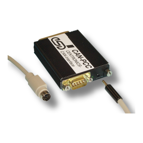
Especially the low-voltage connector has to be connected to the CAN-PCC module first
and only after that the module is to be connected to the PC/laptop! Otherwise live parts
of the low-voltage connector (+5V between the middle contact) could come into contact
with earthed metal parts of the cases and cause a short circuit!
Attention!
Strictly follow the installation notes!
(See chapt. 2 of the hardware manual).
Advertisement
Chapters
Table of Contents

Related Manuals for ESD CAN - PCC


Summary of Contents for ESD CAN - PCC
- Page 1 Attention! Strictly follow the installation notes! (See chapt. 2 of the hardware manual). The order of the individual steps of the hardware installation as specified in the installation notes must be followed at any rate, because otherwise serious damage can be caused to PC or laptop, or to the CAN-PCC module! Especially the low-voltage connector has to be connected to the CAN-PCC module first and only after that the module is to be connected to the PC/laptop! Otherwise live parts...
- Page 2 CAN - PCC CAN Interface For One Parallel Interface Hardware Manual CAN-PCC Hardware Manual Rev. 1.2...
- Page 3 gmbh.
- Page 4 Manual File: I:\TEXTE\DOKU\MANUALS\CAN\CENTRONI\CANPP12H.EN6 Date of Print: 12.03.1998 Version Designation of CANPP-2 Board: Version Designation of CANPP02, Rev. 1.1 Circuit Diagrams: Changes in the chapters The changes in the manual listed below affect changes in the hardware, as well as changes in the description of the facts only.
- Page 5 Attention! Strictly follow the installation notes! (See chapt. 2 of the hardware manual). The order of the individual steps of the hardware installation as specified in the installation notes must be followed at any rate, because otherwise serious damage can be caused to PC or laptop, or to the CAN-PCC module! Especially the low-voltage connector has to be connected to the CAN-PCC module first and only after that the module is to...
-
Page 6: Table Of Contents
Contents Page 1. Overview ..............3 1.1 Module Description . - Page 7 CAN-PCC Hardware Manual Rev. 1.2...
-
Page 8: Overview
Overview 1. Overview 1.1 Module Description The module offers a bidirectional interface between CENTRONICS and CAN, and therefore an easy and inexpensive coupling of a PC, laptop, or something similar, to the CAN. By means of the CAN-PCC module other CAN modules can be controlled or monitored for instance by a PC. - Page 9 Overview Data is transferred from the CENTRONICS interface to the CAN byte by byte. Data which is transferred vice versa (CAN to CENTRONICS) can also be transferred byte by byte. Older PC-CENTRONICS interfaces, however, do not always have a bidirectional data path. The software contained in the product package recognizes this and then uses the control lines for the data transfer.
-
Page 10: Case View
Overview 1.2 Case View P1 - CENTRONICS (25-pole DSUB connector) outer thread 4-40 UNC inner thread 4-40 UNC 15.8 P2 - voltage supply (female with 1.3 mm stud) P3 - CAN status-LED (green) (9-pole DSUB connector) Fig. 1.2.1: Dimensions and connector designations of the CAN-PCC module CAN-PCC Hardware Manual Rev. -
Page 11: General Technical Data Of The Interface Module
Overview 1.3 General Technical Data of the Interface Module permissible ambient temperature: 0...50 EC Temperature range Humidity max. 90%, non-condensing input-voltage range: 5.0 V (DC) ... 9 V (DC) permissible residual ripple: Î U < 100 mV ( f < 100 kHz) Supply voltage . -
Page 12: Technical Data Of The Miniature Connector-Power Pack
Overview 1.4 Technical Data of the Miniature Connector-Power Pack The miniature connector-power pack is not contained in the product package. permissible ambient temperature: 0...50 EC Temperature range Humidity max. 90%, non-condensing U = 230 V ±10% Mains voltage f = 45...60 Hz Output voltage = 6 V ±10% 230 V (AC): power-pack case... -
Page 13: Can- And Μcontroller Units
Overview 1.5 CAN- and µController Units CAN interface physical layer in accordance with ISO 11898, Transmission rate programmable from 10 kbit/s to 1 Mbit/s CAN identifiers the module supports 2048 CAN identifiers µcontroller 87C592, 16 Mhz memory for CAN parameters EEPROM (not yet supported) LED display... -
Page 14: Software Support
Overview 1.6 Software Support The complete firmware is contained in the product package. The firmware contains the local driver software which is stored in the EPROM of the CAN controller and a user interface, which can be found on 3.5" disks as a Microsoft C-Library. This library can be used with WINDOWS - operating sytems from version 3.0. - Page 15 CAN-PCC Hardware Manual Rev. 1.2...
-
Page 16: Order Information
Order Information 1.7 Order Information Type Properties Order no. CAN-CENTRONICS interface, incl. PC CAN-PCC C.2422.01 software Adaptor cable for voltage tapping from keyboard cable via MINI-DIN connectors (is CAN-PCC-ADPT-MDIN C.2422.12 needed for voltage supply via laptop or notebook) Adaptor cable for voltage tapping from CAN-PCC-ADPT-DIN keyboard cable via DIN connectors (is needed C.2422.13... - Page 17 CAN-PCC Hardware Manual Rev. 1.2...
-
Page 18: Installation Notes
Installation 2. Installation Notes The order for the individual steps of the hardware installation must strictly be followed, because otherwise serious damage can be caused at PC or laptop or at the CAN-PCC module!! For wiring please use only the adaptors and lines provided. Keep to the following steps to install the module: Switch off the PC or laptop. - Page 19 CAN-PCC Hardware Manual Rev. 1.2...
-
Page 20: Unit Description
3.1.2 Transmit- and Receive Circuit of the CAN Interface (Physical Layer) The physical interface of the esd-CAN is in accordance with the ISO 11898 norm. The interface is connected to the busline via a male 9-pole DSUB connector (P3). -
Page 21: Centronics Interface
Unit Description 3.2 CENTRONICS Interface The CENTRONICS interface can be connected via a male 25-pole DSUB connector. The data and control signals are transmitted and received by CMOS logic components (e.g. HC244). The data signals and the control signals 'AUTOFEED', 'RESET' and 'SELECT_IN' have 4.7 kS-pull-up resistors at +5 V. -
Page 22: Status Led
Unit Description 3.3 Status LED Depending on the current module status the status LED changes into various flash status. These are listed in the table below. Status of Status of CAN module status LED LED flashes: Module status OK, 250 ms green, initialisation of the controller with bitrate has occurred. - Page 23 CAN-PCC Hardware Manual Rev. 1.2...
-
Page 24: Appendix
Pin Assignment 4. Appendix 4.1 Connector Assignments 4.1.1 CENTRONICS Connector P1 Signal Signal STROBE* AUTOFEED ERROR RESET* SELEC_IN* ACK_IRQ* BUSY SLCT 25-pole male DSUB connector CAN-PCC Hardware Manual Rev. 1.2... -
Page 25: Can Connector P3 (9-Pole Male Dsub Connector)
Pin Assignment 4.1.2 CAN Connector P3 (9-pole male DSUB connector) Pin Orientation: Pin Assignment: Signal Signal reserviert CAN_GND CAN_L CAN_H CAN_GND reserviert reserviert reserviert reserviert CAN-PCC Hardware Manual Rev. 1.2... -
Page 26: Circuit Diagrams
Circuit Diagrams 4.2 Circuit Diagrams CAN-PCC Hardware Manual Rev. 1.2... - Page 27 CAN-PCC Windows 3.11 API Software Manual CAN-PCC Software Manual Rev. 1.4...
- Page 28 gmbh.
- Page 29 Manual File: I:\TEXTE\DOKU\MANUALS\CAN\CENTRONI\CANPP14S.EN6 12.03.98 Date of Print: CAN-PCC software Described Software: Revision/Date: Rev. 1.0 / 05.97 Changes in the software and/or documentation Alterations in Alterations in the Alterations in this manual versus version 1.3 the software documentation First English issue (manual). CAN-PCC Software Manual Rev.
- Page 30 Contents Page 1. Overview ..............3 1.1 About the Software Documentaion .
- Page 31 CAN-PCC Software Manual Rev. 1.4...
-
Page 32: Overview
1. Overview 1.1 About the Software Documentaion This manual describes the Windows 3.11 software of the CAN-PCC. Following this overview and the installation notes, the functions will be explained which can be used by the user. The software requires further functions which are not to be used by the user, however. Still, they will be explained shortly, because they also appear in the header file. -
Page 33: Product Package
For information CPCC .INI Installation notes INFO .TXT Notes on setting the bitrate NOTE .ESD Notes on the disk README .TXT \SAMPLES Include file with functional prototypes and structure definitions Source file of the main module of the test program BAC2_TST.C Source file of the dialogue-box routines for the initialisation BINI_DLG.C... -
Page 34: Configuration Of The Parallel Interface
2. Configuration of the Parallel Interface It is important to check and possibly adapt the setting of the parallel interface of the PC. The configuration of the interface depends on the PC and the BIOS used. The following description is therefore only exemplatory: 1. -
Page 35: Software Installation
3. Software Installation This chapter describes the software installation on the PC. For hardware installation of the module refer to the hardware manual. Installation: 1. Remove all programs and drivers which can access the CENTRONICS interface you have selected. 2. Generate (manually) a directory on your harddisk for the CAN-PCC software and copy the desired files (DLL) from the disk into your new directory. -
Page 36: Operating Modes Of The Can-Pcc Library
4. Operating Modes of the CAN-PCC Library The CAN controller used supports only 11-bit identifiers. Parameters which require 29-bit identifiers are for future applications. Principally two modes are possible for buffering CAN messages: The FIFO mode and the CAN-object mode. In this software version, however, only the FIFO mode is implemented. 4.1 FIFO Mode Messages which have been received or which are to be transmitted are sequentially exchanged between the CAN and the PC, like a FIFO (first-in-first-out). - Page 37 CAN-PCC Software Manual Rev. 1.4...
-
Page 38: Functions Of The Can-Pcc Library
5. Functions of the CAN-PCC Library 5.1 Executable Functions 5.1.1 CANPC_reset_chip By means of this command a possibly running CAN transmission is terminated, the CENTRONICS port is reset and the CPCC.INI is read out of the program. CANPC_reset_chip(void) Input parameter: Output parameter: RESET was successful 0... -
Page 39: Canpc_Initialize_Chip
5.1.2 CANPC_initialize_chip By means of this function the bit timing of the CAN controller is defined. The parameters presc, sjw, tseg1 and tseg2 are transferred into the bit-timing register of the CAN controller. The values of these parameters describe the bit timing of the CAN protocol. The bitrate is calculated with the following formula, however, further marginal conditions have to be considered (for this refer to the data sheet of CAN controller 87C592) crystal... - Page 40 int CANPC_initialize_chip( int presc, int sjw, int tseg1, int tseg2, int sam) Input parameters: CAN prescaler [1..32] presc... CAN-synchronisation-jump width [1..4] sjw... CAN-time-segment 1 [1..16] tseg1... CAN-time-segment 2 [1..8] tseg2... CAN-sample mode 0... 1 sample sam... 1... 3 samples Output parameters: 0...
-
Page 41: Canpcc_Inibit
5.1.3 CANPCC_inibit Like CANPC_initialize_chip this function defines the bit timing of the CAN controller. Here, however, the bitrate is set by transmitting an index value of 0...15 or by transmitting the parameters btr0 and brt1. Only this function sets a bitrate on the module. Before that the controller does not operate on the CAN! The typical line lengths specified below are based on facts from experience. - Page 42 int CANESDinibit(rate) Input parameters: Depending on the value range specified, the parameter rate is rate... evaluated in different ways. It stands either for the parameter index or for the two parameters btr0 and btr1. The meaning of these parameters is shown in the table above. [$0000...$000E]...
-
Page 43: Canpc_Set_Acceptance
5.1.4 CANPC_set_acceptance By means of this command a reception filter for CAN-data frames and remote-request frames can be made. This filter can be generated for standard or extended-CAN identifiers. Only those frames are received whose identifier bits are compliant to the acceptance filter. The values of the bits which have been initialized with a '1' in the parameter AccMask... - Page 44 5.1.5 CANPCC_enable_id and CANPCC_disable_id By means of this command a receive filter for individual or various data or remote frames can be generated or taken back. By calling this function several times it is furthermore possible to select various identifier groups. The selection is made by entering the first and the last identifier which is to be received.
-
Page 45: Canpc_Send_Data
5.1.7 CANPC_send_data By means of this command a data frame with the specified parameters is transmitted to the CAN. int CANPC_send_data( unsigned long Ident, Xtd, DataLength, byte *pData) Input parameters: Identifier [$0000...$07FF, $00000000...$1FFFFFFF] Ident... Identifier length Standard identifier Xtd... Extended identifier (is not being supported) Number of data bytes to be transmitted.[0...8] DataLength... -
Page 46: Canpc_Send_Remote
5.1.8 CANPC_send_remote By means of this command a remote frame with the specified parameters is transmitted to the CAN. The transmitted remote frame has always the length '0'. The number of transmitted data bytes (here 0) is transmitted nevertheless in the parameter DataLength. int CANPC_send_remote( unsigned long Ident, Xtd,... -
Page 47: Canpc_Read_Ac
5.1.9 CANPC_read_ac By means of this function the application is informed about the transmission and the reception of messages and various error status. This function has be requested by polling. The output codes 1...12 (RC1 to RC12) define the relevant elements of the returned structured. int CANPC_read_ac( param_struct*write_ac_param ) Elements of the structure param_struct: Identifier of a received or transmitted frame (RC1,... - Page 48 Further error causes (RC7): int Error_state... no error 0... hardware FIFO is inconsistent (-> overflow or 8... connection is disturbed) is not set int CAN... Time of the displayed events with a resolution of 1 µs. The counter unsigned long Time... is reset by CANPC_start_chip.
-
Page 49: Further Functions
5.2 Further Functions The following functions have been implemented for reasons of compatibility to earlier software versions. Even though the functions are listed in the header file, the user has no right to these functions and should not use them. Calling them does not trigger an error message: INIPC_initialize_board CANPC_reset_board CANPC_set_mode... -
Page 50: The Command Sequence
5.3 The Command Sequence 5.3.1 Chronologial Order of Commands The commands of the CAN-PCC library have to be called in a fixed chronological order (command sequence): After starting the program, the CAN-controller component has to be reset by calling CANPC_reset_chip. By calling the command CANPC_inibit or CANPC-initialize_chip the controller component is initialized (bitrate). -
Page 51: Graphical Display Of The Command Sequence
5.3.2 Graphical Display of the Command Sequence CANPC_reset_chip alternatively CANPC_inibit CANPC_initialize_chip alternatively CANPCC_enable_id CANPC_set_acceptance CANPCC_disable_id CANPC_enable_fifo_transmit_ack CANPC_send_data CANPC_send_remote CANPC_read_ac CAN-PCC Software Manual Rev. 1.4... - Page 52 CAN-PCC Software Manual Rev. 1.4...
Need help?
Do you have a question about the CAN - PCC and is the answer not in the manual?
Questions and answers