Table of Contents
Advertisement
Quick Links
CAN-USB/Micro
Small CAN USB Interface
in DSUB9 Enclosure
Manual
to Product C.2068.xx
CAN-USB/Micro
Manual • Doc. No.: C.2068.21 / Rev. 1.2
Page 1 of 23
esd electronic system design gmbh
Vahrenwalder Str. 207 • 30165 Hannover • Germany
http://www.esd.eu
Phone: +49 (0) 511 3 72 98-0 • Fax: +49 (0) 511 3 72 98-68
Advertisement
Table of Contents

Related Manuals for ESD CAN-USB/Micro


Summary of Contents for ESD CAN-USB/Micro
- Page 1 CAN-USB/Micro Manual • Doc. No.: C.2068.21 / Rev. 1.2 Page 1 of 23 esd electronic system design gmbh Vahrenwalder Str. 207 • 30165 Hannover • Germany http://www.esd.eu Phone: +49 (0) 511 3 72 98-0 • Fax: +49 (0) 511 3 72 98-68...
- Page 2 The information in this document has been carefully checked and is believed to be entirely reliable. esd makes no warranty of any kind with regard to the material in this document, and assumes no responsibility for any errors that may appear in this document. In particular descriptions and technical data specified in this document may not be constituted to be guaranteed product features in any legal sense.
- Page 3 CAN transceiver test revised. Editorial revision of the chapter. Order information moved to chapter 12. First version 2011-01-28 Technical details are subject to change without further notice. CAN-USB/Micro Manual • Doc. No.: C.2068.21 / Rev. 1.2 Page 3 of 23...
- Page 4 ● Do not operate the CAN-USB/Micro adjacent to heat sources and do not expose it to unnecessary thermal radiation. Ensure an ambient temperature as specified in the technical data. ● Do not use damaged or defective cables to connect the CAN-USB/Micro and follow the CAN wiring hints in chapter: "Correctly Wiring Electrically Isolated CAN Networks".
-
Page 5: Table Of Contents
CAN-Bus Troubleshooting Guide....................19 8.1 Termination.......................... 19 Electrical Grounding......................20 Short Circuit in CAN Wiring....................20 CAN_H/CAN_L-Voltage ......................20 CAN Transceiver Resistance Test ..................21 Declaration of Conformity......................22 Order Information........................23 CAN-USB/Micro Manual • Doc. No.: C.2068.21 / Rev. 1.2 Page 5 of 23... -
Page 6: Overview
ISO11898-2 Figure 1: Block-circuit diagram of the CAN-USB/Micro The CAN-USB/Micro is a very small, low cost CAN-USB interface for PCs, that fits into a DSUB9 enclosure. The ARM Cortex-M3 micro controller controls the CAN data. The non isolated CAN interface is powered by USB. -
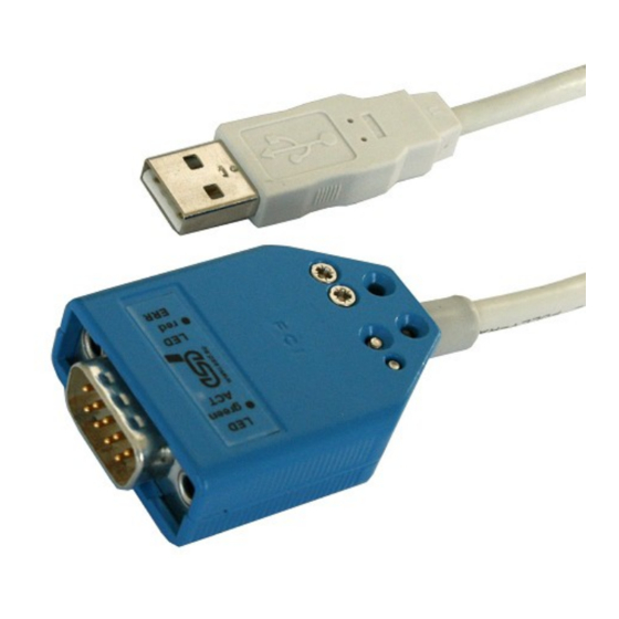
Page 7: View Of The Connectors
View of the Connectors 2. View of the Connectors Figure 2: Connectors of CAN-USB/Micro Page 8 of 23 Manual • Doc. No.: C.2068.21 / Rev. 1.2 CAN-USB/Micro... -
Page 8: Hardware Installation
Procedure: Connect the USB connector of the CAN-USB/Micro to the USB bus of the PC. Connect the 9-pin male DSUB connector to the CAN bus. Please remember that the CAN bus has to be terminated at both ends. esd offers T-connectors and terminators. -
Page 9: Led Description
LED Description 4. LED Description Figure 3: LEDs CAN-USB/Micro Name Colour Description USB module is enumerated (a node address is assigned to the USB module) Activity green flash off receives CAN telegrams or USB commands not working CAN-Bus-off, CAN-Error-passive or... -
Page 10: Summary Of Technical Data
CAN High speed interface according to ISO 11898-2, Physical Layer bit rate up to 1 Mbit/s Electrical isolation none Bus termination has to be set externally Connector DSUB9, according to CiA 303-1 CAN-USB/Micro Manual • Doc. No.: C.2068.21 / Rev. 1.2 Page 11 of 23... -
Page 11: Software Support
The source code of the operating system is published in terms of the GNU Public License (GPL). For the full license text please see esd's “3rd party lisensor notice” document that is part of the product's documentation on the enclosed CD. -
Page 12: Connector Assignment
Device connector: USB connector type A Pin Position: 1 2 3 4 Pin Assignment: Signal Signal Description: +5 V power supply voltage D+, D-... USB signal lines Data+, Data- GND... Reference potential CAN-USB/Micro Manual • Doc. No.: C.2068.21 / Rev. 1.2 Page 13 of 23... -
Page 13: Can
CAN physical layer CAN_GND (CAN_Shield) ... CAN_Shield is connected to shield of the USB wire and to GND reserved ... reserved for future applications, do not connect! Page 14 of 23 Manual • Doc. No.: C.2068.21 / Rev. 1.2 CAN-USB/Micro... -
Page 14: Correctly Wiring Of Can Networks
7.1 General Rules Note: esd only grants the compliance with directive 2004/108/EC, if the CAN wiring is carried out with at least single shielded twisted pair cables that match the requirements of ISO 11898-2. -
Page 15: Cabling
If the used CAN interface is not equipped with an integrated CAN termination and it is at an ● end of the bus, use external termination plugs. 9-pin DSUB-termination connectors with male and female contacts and earth terminal are ● available as accessories. Page 16 of 23 Manual • Doc. No.: C.2068.21 / Rev. 1.2 CAN-USB/Micro... -
Page 16: Earthing
Earthing can e.g. be made at a connector/T-connector. ● 7.5 Bus Length Optical couplers are delaying the CAN signals. esd modules typically reach a wire length of ● 37 m at 1 Mbit/s within a closed net without impedance disturbances like e.g. cable stubs >>... -
Page 17: Examples For Can Cables
Äußerer Eichwald 74535 Mainhardt BUS-Schleppflex-PUR-C (1x 2x 0,25 mm²) Order No.: 94 025 016 (UL appr.) Germany www.concab.de Note: Configured CAN cables can be ordered from esd. Page 18 of 23 Manual • Doc. No.: C.2068.21 / Rev. 1.2 CAN-USB/Micro... -
Page 18: Can-Bus Troubleshooting Guide
- there are no open circuits in CAN_H or CAN_L wiring - your bus system has two terminating resistors (one at each end) and that they are 120 Ω each. CAN-USB/Micro Manual • Doc. No.: C.2068.21 / Rev. 1.2 Page 19 of 23... -
Page 19: Electrical Grounding
Turn on all supplies. Stop all network communication. Measure the DC voltage between CAN_H and GND (see figure above). Measure the DC voltage between CAN_L and GND (see figure above). Page 20 of 23 Manual • Doc. No.: C.2068.21 / Rev. 1.2 CAN-USB/Micro... -
Page 20: Can Transceiver Resistance Test
Another sign for a faulty transceiver is a very high deviation between the two measured input resistance (>> 200%). CAN node CAN_H CAN_L transceiver CAN_GND disconnect Power CAN! disconnect power! Figure 8: Measuring the internal resistance of CAN transceivers CAN-USB/Micro Manual • Doc. No.: C.2068.21 / Rev. 1.2 Page 21 of 23... -
Page 21: Declaration Of Conformity
Declaration of Conformity 9. Declaration of Conformity Page 22 of 23 Manual • Doc. No.: C.2068.21 / Rev. 1.2 CAN-USB/Micro... -
Page 22: Order Information
Table 2: Order information PDF Manuals Manuals are available in English and usually in German as well. For availability of English manuals see table below. Please download the manuals as PDF documents from our esd website www.esd.eu for free. Manuals Order No.
Need help?
Do you have a question about the CAN-USB/Micro and is the answer not in the manual?
Questions and answers