Sign In
Upload
Manuals
Brands
ESD Manuals
Control Unit
CAN-USB/3-FD
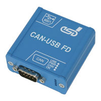
User Manuals: ESD CAN-USB/3-FD USB Module CAN
Manuals and User Guides for ESD CAN-USB/3-FD USB Module CAN. We have
2
ESD CAN-USB/3-FD USB Module CAN manuals available for free PDF download: Hardware Manual
ESD CAN-USB/3-FD Hardware Manual (31 pages)
Brand:
ESD
| Category:
Recording Equipment
| Size: 1 MB
Table of Contents
Safety Instructions
5
Table of Contents
7
Overview
9
About this Manual
9
Description of CAN-USB/3-FD
9
Figure 1: Block Circuit Diagram
9
Glossary
10
Module Views, Connectors and Leds
11
Module View
11
CAN-USB/3-FD-Dinrail Back Side
11
Figure 2: CAN-USB/3-FD Front View
11
Figure 3: Module with Mounting Rail Holder (CAN-USB/3-FD-Dinrail Only)
11
Top View with USB Interface
12
Bottom View with CAN Connector and Leds
12
LED Description
12
Table 1: Description of Leds
12
Figure 4: Module Top View with USB Interface
12
Figure 5: Module View with CAN Connector and Leds
12
Hardware Installation
13
Technical Data
14
General Technical Data
14
USB and CPU
14
Table 2: General Data of the Module
14
Table 3: USB Interface and Microcontroller
14
Connectors Accessible from Outside
15
CAN FD Interface
15
Table 4: Connectors, Accessible from Outside
15
Table 5: Data of the CAN Interface
15
Software Support
16
License
17
Connector Assignments
18
Can (Dsub9)
18
USB Socket
19
Correct Wiring of Electrically Isolated CAN Networks
20
CAN Wiring Standards
20
Light Industrial Environment (Single Twisted Pair Cable)
21
General Rules
21
Figure 6: CAN Wiring for Light Industrial Environment
21
Cabling
22
Branching
22
Termination Resistor
22
Figure 7: Example for Proper Wiring with Single Shielded Single Twisted Pair Wires
22
Heavy Industrial Environment (Double Twisted Pair Cable)
23
General Rules
23
Figure 8: CAN Wiring for Heavy Industrial Environment
23
Device Cabling
24
Branching
24
Termination Resistor
24
Figure 9: Example of Proper Wiring with Single Shielded Double Twisted Pair Cables
24
Electrical Grounding
25
Bus Length
25
Table 6: Recommended Cable Lengths at Typical Bit Rates (with Esd-CAN Interfaces)
25
Examples for CAN Cables
26
Cable for Light Industrial Environment Applications (Two-Wire)
26
Cable for Heavy Industrial Environment Applications (Four-Wire)
26
CAN Troubleshooting Guide
27
Termination
27
Figure 10: Simplified Diagram of a CAN Network
27
Electrical Grounding
28
Short Circuit in CAN Wiring
28
Correct Voltage Levels on CAN_H and CAN_L
28
Figure 11: Simplified Schematic Diagram of Ground Test Measurement
28
CAN Transceiver Resistance Test
29
Support by Esd
29
Figure 12: Measuring the Internal Resistance of CAN Transceivers
29
Declaration of Conformity
30
Order Information
31
Hardware
31
Software for CAN-USB/3-FD
31
Manuals
31
Table 7: Order Information Hardware
31
Table 8: Order Information Software for CAN-USB/3-FD-FD
31
Table 9: Available Manuals
31
Advertisement
ESD CAN-USB/3-FD Hardware Manual (31 pages)
USB 2.0 Module with CAN FD Interface
Brand:
ESD
| Category:
Control Unit
| Size: 1 MB
Table of Contents
Safety Instructions
5
Table of Contents
7
1 Overview
9
Description of CAN-USB/3-FD
9
Figure 1: Block Circuit Diagram
9
Glossary
10
2 Case View with Connectors and Leds
11
Figure 3: USB Interface
11
Figure 2: CAN Connector and Leds
11
LED-Displays
12
Table 1: Description of Leds
12
3 Hardware Installation
13
Table 3: USB Interface and Microcontroller
14
Table 2: General Data of the Module
14
CAN FD Interface
15
Connectors Accessible from Outside
15
4 Technical Data
14
General Technical Data
14
USB and CPU
14
Table 5: Data of the CAN Interface
15
Table 4: Connectors, Accessible from Outside
15
Software Support
16
License
17
5 Connector Assignments
18
Can (Dsub9)
18
USB Socket
19
6 Correct Wiring of Electrically Isolated CAN Networks
20
Standards Concerning CAN Wiring
20
Figure 4: CAN Wiring for Light Industrial Environment
21
Figure 5: Example for Proper Wiring with Single Shielded Single Twisted Pair Wires
22
Figure 6: CAN Wiring for Heavy Industrial Environment
23
Branching
24
Device Cabling
24
Figure 7: Example of Proper Wiring with Single Shielded Double Twisted Pair Cables
24
Termination
24
Bus Length
25
Electrical Grounding
25
Table 6: Recommended Cable Lengths at Typical Bit Rates (with Esd-CAN Interfaces)
25
Cable for Heavy Industrial Environment Applications (Four-Wire)
26
Cable for Light Industrial Environment Applications (Two-Wire)
26
Examples for CAN Cables
26
Figure 8: Simplified Diagram of a CAN Network
27
CAN_H/CAN_L-Voltage
28
Electrical Grounding
28
Short Circuit in CAN Wiring
28
Termination
22
Heavy Industrial Environment (Double Twisted Pair Cable)
23
General Rules
23
Light Industrial Environment (Single Twisted Pair Cable)
21
General Rules
21
Branching
22
Cabling
22
7 CAN Troubleshooting Guide
27
Termination
27
Figure 9: Simplified Schematic Diagram of Ground Test Measurement
28
CAN Transceiver Resistance Test
29
Support by Esd
29
Figure 10: Measuring the Internal Resistance of CAN Transceivers
29
8 Declaration of Conformity
30
Table 7: Order Information Hardware
31
Table 8: Order Information Software for CAN-USB/3-FD-FD
31
Table 9: Available Manuals
31
9 Order Information
31
Hardware
31
Software for CAN-USB/3-FD
31
Manuals
31
Advertisement
Related Products
ESD CAN-USB/2
ESD CAN-USB/400-FD-IRIG-B
ESD CAN-CBX-Pt100
ESD CAN-CBX-AO412
ESD CAN-CBM-REL4
ESD CAN-CBM-AI410
ESD CAN-CBX-DIO8
ESD CAN-CBX-DIO8-J1939
ESD C.2066.21
ESD C.3032.02
ESD Categories
Recording Equipment
Computer Hardware
Gateway
PCI Card
Control Unit
More ESD Manuals
Login
Sign In
OR
Sign in with Facebook
Sign in with Google
Upload manual
Upload from disk
Upload from URL