Table of Contents
Advertisement
Quick Links
CAN-CBM-CLOCK
Real Time Clock with CAN Interface
Hardware-Manual
to Product C.2836.03
CAN-CBM-Clock
Page 1 of 34
Hardware Manual • Doc.-No.: C.2836.21 / Rev. 1.3
e s d e le c t ro n ic s y s te m d e s ig n g m b h
V a h re n w a ld e r S tr. 2 0 7 • 3 0 1 6 5 H a n n o v e r • G e rm a n y
h ttp ://w w w .e s d .e u
P h o n e : + 4 9 (0 ) 5 1 1 3 7 2 9 8 -0 • F a x : + 4 9 (0 ) 5 1 1 3 7 2 9 8 -6 8
Advertisement
Table of Contents

Subscribe to Our Youtube Channel
Related Manuals for ESD CAN-CBM-CLOCK


Summary of Contents for ESD CAN-CBM-CLOCK
- Page 1 CAN-CBM-CLOCK Real Time Clock with CAN Interface Hardware-Manual to Product C.2836.03 CAN-CBM-Clock Page 1 of 34 Hardware Manual • Doc.-No.: C.2836.21 / Rev. 1.3 e s d e le c t ro n ic s y s te m d e s ig n g m b h V a h re n w a ld e r S tr.
- Page 2 The information in this document has been carefully checked and is believed to be entirely reliable. esd makes no warranty of any kind with regard to the material in this document, and assumes no responsibility for any errors that may appear in this document. In particular descriptions and technical data specified in this document may not be constituted to be guaranteed product features in any legal sense.
- Page 3 Description of CAN connector added New chapter: “Conductor Connection/ Conductor Cross Section” 6, 7 Chapters revised Order information moved and revised Technical details are subject to change without further notice. CAN-CBM-Clock Page 3 of 34 Hardware Manual • Doc.-No.: C.2836.21 / Rev. 1.3...
- Page 4 This NOTICE statement contains the general mandatory sign and gives information that must be heeded and complied with for a safe use. INFORMATION INFORMATION Notes to point out something important or useful. Page 4 of 34 CAN-CBM-Clock Hardware Manual • Doc.-No.: C.3010.21 / Rev. 1.3...
- Page 5 Intended Use The intended use of the CAN-CBM-Clock module is the operation as a real time clock with CAN interface. The esd guarantee does not cover damages which result from improper use, usage not in accordance with regulations or disregard of safety instructions and warnings.
- Page 6 The operation of the CAN-CBM-Clock module for medical purposes is prohibited. Service Note The CAN-CBM-Clock module does not contain any parts that require maintenance by the user except the battery. Unauthorized intervention to the device voids warranty claims. For a battery change the case has to be opened.
-
Page 7: Table Of Contents
6.6.1 Cable for Light Industrial Environment Applications (Two-Wire) ... . . 30 6.6.2 Cable for Heavy Industrial Environment Applications (Four-Wire) ... . 30 CAN-CBM-Clock Page 7 of 34... - Page 8 7.6 Support by esd ........
-
Page 9: Overview
5-pin screw-/ plug connector in Combicon style. The connection for the external time receiver is designed as serial RS232-interface with a DSUB9 connector. CAN-CBM-Clock Page 9 of 34 Hardware Manual • Doc.-No.: C.2836.21 / Rev. 1.3... -
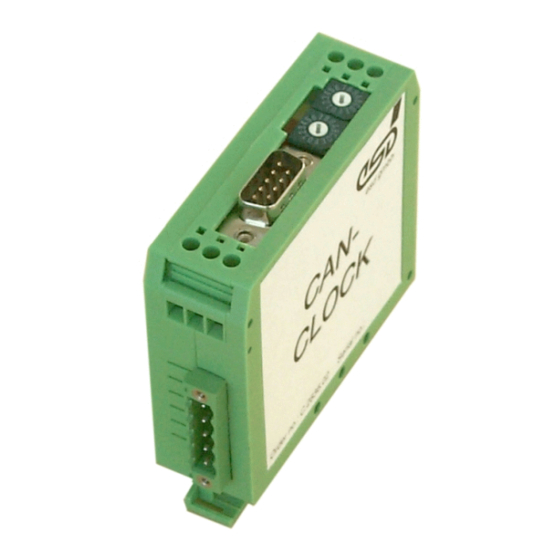
Page 10: View Of The Module With Connectors And Coding Switches
1.2 View of the Module with Connectors and Coding Switches Figure 2: Position of the connectors and coding switches NOTICE Read chapter “Quick Start” on page 19, before you start with the installation of the hardware! Page 10 of 34 CAN-CBM-Clock Hardware Manual • Doc.-No.: C.3010.21 / Rev. 1.3... -
Page 11: Technical Data
Table 1: General technical data 2.2 Microcontroller Unit Microcontroller MB90F543 SRAM: integrated in MB90F543, 6 Kbyte Memory Flash-EPROM: integrated in MB90F543, 128 Kbyte Table 2: Microcontroller Unit CAN-CBM-Clock Page 11 of 34 Hardware Manual • Doc.-No.: C.2836.21 / Rev. 1.3... -
Page 12: Can Interface
Physikalisch-Technische Bundesanstalt, transmitter: Mainflingen, reach approx. 2000 highly stable carrier frequency: 77.5 kHz e.g.: Expert mouseClock of Gude GmbH Table 4: Data of the serial interface Page 12 of 34 CAN-CBM-Clock Hardware Manual • Doc.-No.: C.3010.21 / Rev. 1.3... -
Page 13: Rtc
Technical Data 2.5 RTC The CAN-CBM-Clock module is equipped with an internal RTC (Real Time Clock). The RTC is powered by a lithium coin cell. For a battery change the case of the CAN-CBM-Clock module has to be opened. NOTICE The battery change may only be carried out by qualified personal! It is recommended to send the CAN-CBM-Clock module to esd for the battery change after 5 years. -
Page 14: Description Of The Units
Description of the Units 3. Description of the Units 3.1 CAN Interface 3.1.1 Interface Circuit Figure 3: Circuit of the CAN interfaces Page 14 of 34 CAN-CBM-Clock Hardware Manual • Doc.-No.: C.3010.21 / Rev. 1.3... -
Page 15: Serial Interface
Description of the Units 3.2 Serial Interface 3.2.1 Default Setting of the Module Bit rate: 4800 baud Data bits: Parity: Stop bits: Handshake: none CAN-CBM-Clock Page 15 of 34 Hardware Manual • Doc.-No.: C.2836.21 / Rev. 1.3... -
Page 16: Setting Node Number And Can Bit Rate Via Coding Switch
Select the bit rate and position switch SW100 correspondingly (table of bit rates see below) To accept the new bit rate position the switch to ‘1’; LED141 turns off Switch off the module Set CANopen node number (see page 17) Page 16 of 34 CAN-CBM-Clock Hardware Manual • Doc.-No.: C.3010.21 / Rev. 1.3... -
Page 17: Assignment Of The Position Of The Coding Switch To The Can Bit Rates
: CANopen node number (nibble assignment, see above) Switch on the module If the coding switches are positioned to a value between 01 ...7F , this value is interpreted as node number. CAN-CBM-Clock Page 17 of 34 Hardware Manual • Doc.-No.: C.2836.21 / Rev. 1.3... -
Page 18: Led Display
Bit rate setting mode is active Module off or no failure Failure LED140 Failure, no bit rate is set Table 8: Meaning of the indicator states of the LEDs Page 18 of 34 CAN-CBM-Clock Hardware Manual • Doc.-No.: C.3010.21 / Rev. 1.3... -
Page 19: Quick Start
Mount the CAN-CBX-module and connect the interfaces (power supply voltage, CAN, serial interface). Please note that the CAN bus has to be terminated at both ends! esd offers special T-connectors and termination connectors. Additionally the CAN_GND signal has to be connected to earth at exactly one point in the CAN network. -
Page 20: Connector Assignment
CAN physical layers Shield... shielding The 9-pin DSUB connector is assigned in accordance with CiA DS 102. Figure 4: Adapter cable 5-pin connector plug to 9-pin DSUB Page 20 of 34 CAN-CBM-Clock Hardware Manual • Doc.-No.: C.3010.21 / Rev. 1.3... -
Page 21: Conductor Connection/Conductor Cross Sections
2 conductors with same cross section, stranded, 0.5 mm²/1.5 mm² TWIN ferrules with plastic sleeve, min./max. Minimum/Maximum AWG according to UL/CUL 30/12 Technical Data from Phoenix Contact website, connector plug CAN-CBM-Clock Page 21 of 34 Hardware Manual • Doc.-No.: C.2836.21 / Rev. 1.3... -
Page 22: Serial Interface (X100, 9 Pin Dsub, Male)
DCF77-receiver (e.g.: Expert mouseClock of Gude) -Vcc_help... -9 V output voltage auxiliary supply for DCF77-receiver Vcc_ out... 5 V output voltage power supply voltage for other DCF77- or GPS-receiver Page 22 of 34 CAN-CBM-Clock Hardware Manual • Doc.-No.: C.3010.21 / Rev. 1.3... -
Page 23: Power Supply (X101, Uegm)
It is not permissible to feed-through the 24 V-supply voltage, i.e. to use one side as 24 V input and the other side as 24 V output in order to supply other devices! Figure 5: Voltage supply CAN-CBM-Clock Page 23 of 34 Hardware Manual • Doc.-No.: C.2836.21 / Rev. 1.3... -
Page 24: Correct Wiring Of Electrically Isolated Can Networks
Therefore the practical maximum number of nodes, bus length and stub length are typically much lower. esd has concentrated her recommendations concerning CAN wiring on the specifications of the ISO 11898-2. Thus the special features of the derived standards CANopen, ARINC825, DeviceNet and NMEA2000 are not described in this wiring hints. -
Page 25: Light Industrial Environment (Single Twisted Pair Cable)
Select a working combination of bit rate and cable length. Keep away cables from disturbing sources. If this cannot be avoided, double shielded wires are recommended. Figure. 6: CAN wiring for light industrial environment CAN-CBM-Clock Page 25 of 34 Hardware Manual • Doc.-No.: C.2836.21 / Rev. 1.3... -
Page 26: Cabling
9-pin DSUB-termination connectors with integrated termination resistor and male and female contacts are available from esd (order no. C.1303.01). DSUB termination connectors with male contacts (order no. C.1302.01) or female contacts (order no. C.1301.01) and additional functional earth contact are available, if CAN termination and grounding of CAN_GND is required. -
Page 27: Heavy Industrial Environment (Double Twisted Pair Cable)
Select a working combination of bit rate and cable length. Keep away CAN cables from disturbing sources. If this cannot be avoided, double shielded cables are recommended. Fig. 8: CAN wiring for heavy industrial environment CAN-CBM-Clock Page 27 of 34 Hardware Manual • Doc.-No.: C.2836.21 / Rev. 1.3... -
Page 28: Device Cabling
DSUB9-connector from ERNI (ERBIC CAN BUS MAX, order no.:154039). The usage of esd’s T-connector type C.1311.03 is not recommended for single shielded double twisted pair cables because the shield potential of the conductive DSUB housing is not looped through this T-connector type. -
Page 29: Electrical Grounding
7300 5000 Table 9: Recommended cable lengths at typical bit rates (with esd-CAN interfaces) Optical couplers are delaying the CAN signals. esd modules typically reach a wire length of 37 m CAN-CBM-Clock Page 29 of 34 Hardware Manual • Doc.-No.: C.2836.21 / Rev. 1.3... -
Page 30: Examples For Can Cables
> 0.3 m. 6.6 Examples for CAN Cables esd recommends the following two-wire and four-wire cable types for CAN network design. These cable types are used by esd for ready-made CAN cables, too. 6.6.1 Cable for Light Industrial Environment Applications (Two-Wire) -
Page 31: Can Troubleshooting Guide
- there are no open circuits in CAN_H or CAN_L wiring - your bus system has two terminating resistors (one at each end) and that they are 120 each. CAN-CBM-Clock Page 31 of 34 Hardware Manual • Doc.-No.: C.2836.21 / Rev. 1.3... -
Page 32: Electrical Grounding
(see figure at previous page). Measure the DC voltage between CAN_L and CAN_ GND (see figure at previous page). Normally the voltage should be between 2.0 V and 3.0 V. Page 32 of 34 CAN-CBM-Clock Hardware Manual • Doc.-No.: C.3010.21 / Rev. 1.3... -
Page 33: Can Transceiver Resistance Test
(>> 200%). Figure 12: Simplified diagram of a CAN node 7.6 Support by esd If you have executed the fault diagnostic steps of this troubleshooting guide and you even can not find a solution for your problem our support department will be able to assist. -
Page 34: Order Information
Table 10: Order information PDF Manuals Manuals are available in English and usually in German as well. For availability of English manuals see the following table. Please download the manuals as PDF documents from our esd website www.esd.eu for free.
Need help?
Do you have a question about the CAN-CBM-CLOCK and is the answer not in the manual?
Questions and answers