Table of Contents
Advertisement
Quick Links
CAN-PC104/331
PC/104-CAN-Interface
CAN-PC104/331-2
Hardware Installation
and
Technical Data
to Product C.2012.02, C.2012.04, C.2012.09
CAN-PC104/331
Hardware Manual • Doc. No.: C.2012.21 / Rev. 1.6
Page 1 of 32
esd electronic system design gmbh
Vahrenwalder Str. 207 • 30165 Hannover • Germany
http://www.esd.eu
Phone: +49 (0) 511 3 72 98-0 • Fax: +49 (0) 511 3 72 98-68
Advertisement
Table of Contents

Subscribe to Our Youtube Channel
Related Manuals for ESD CAN-PC104/331


Summary of Contents for ESD CAN-PC104/331
- Page 1 CAN-PC104/331 Hardware Manual • Doc. No.: C.2012.21 / Rev. 1.6 Page 1 of 32 esd electronic system design gmbh Vahrenwalder Str. 207 • 30165 Hannover • Germany http://www.esd.eu Phone: +49 (0) 511 3 72 98-0 • Fax: +49 (0) 511 3 72 98-68...
- Page 2 The information in this document has been carefully checked and is believed to be entirely reliable. esd makes no warranty of any kind with regard to the material in this document, and assumes no responsibility for any errors that may appear in this document. In particular descriptions and technical data specified in this document may not be constituted to be guaranteed product features in any legal sense.
- Page 3 DeviceNet option deleted 2015-12-07 Description of cable revised Note revised Chapter revised Chapter “Order Information” moved and revised Technical details are subject to change without further notice. CAN-PC104/331 Hardware Manual • Doc. No.: C.2012.21 / Rev. 1.6 Page 3 of 32...
- Page 4 This NOTICE statement contains the general mandatory sign and gives information that must be heeded and complied with for a safe use. INFORMATION INFORMATION Notes to point out something important or useful. Page 4 of 32 Hardware Manual • Doc. No.: C.2012.21 / Rev. 1.6 CAN-PC104/331...
-
Page 5: Safety Instructions
● Do not use damaged or defective cables to connect the CAN-PC104/331 and follow the CAN wiring hints in chapter: "Correct Wiring of Electrically Isolated CAN Networks". - Page 6 Intended Use The intended use of the CAN-PC104/331 is the operation as PC/104-CAN-Interface. The guarantee given by esd does not cover damages which result from improper use, usage not in accordance with regulations or disregard of safety instructions and warnings.
-
Page 7: Table Of Contents
Interface........................16 Software Support......................... 16 Connector Pin Assignment......................17 CAN Bus Interface at DSUB9 (X400, X401)................17 Version CAN-PC104/331-2-Micro-Match..................18 5.1 Overview..........................18 Pin Assignment Micro-Match Socket..................19 Adapter Cable Micro-Match (male) to DSUB9(male)............20 Correct Wiring of Electrically Isolated CAN Networks..............21 Standards concerning CAN Wiring..................21... -
Page 8: Overview
PC/104 Connector +5 V= Figure 1: Block circuit diagram of CAN-PC104/331-2 The CAN-PC104 board is a CAN module designed for the PC/104-bus (PC/104 16 bits). It uses a 68331 microcontroller, which cares for the local management. The CAN data is buffered in a local SRAM. -
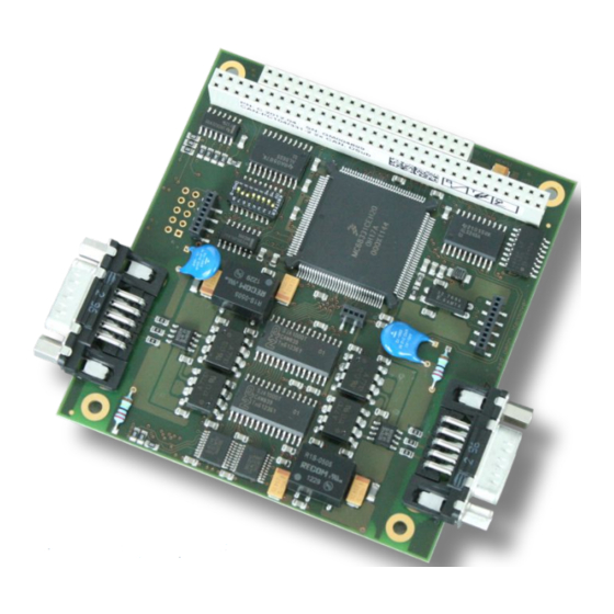
Page 9: Pcb View With Connectors
1.2 PCB View with Connectors CAN 1 CAN 0 X401 X400 X201 BDM-Interface X100 X101 S100 Figure 2: View of PCB layer CAN-PC104/331-2 (without a front panel) CAN-PC104/331 Hardware Manual • Doc. No.: C.2012.21 / Rev. 1.6 Page 9 of 32... -
Page 10: Connector Position And Board Dimensions
Overview 1.3 Connector Position and Board Dimensions 96,0 86,0 55,0 DSUB 9 All listed values are given in millimetre. Figure 3: CAN-PC104/331-2 technical drawing Page 10 of 32 Hardware Manual • Doc. No.: C.2012.21 / Rev. 1.6 CAN-PC104/331... -
Page 11: Hardware Installation
I/O Port. A list with the used and available address ranges appears. Make sure that the default value of the CAN-PC104/331 is in a free memory area. If it is not, note one free memory area (which corresponds to the choices stated in fig. 2.2.2) and change the CAN-PC104/331 address by means of the coding switch during the hardware installation described below. -
Page 12: Execute Hardware Installation And Setting Of Pc/104-Bus Address
Hardware Installation 2.2 Execute Hardware Installation and Setting of PC/104-Bus Address The CAN-PC104/331 module can be used in all PC/104-compatible 16-bit systems (e.g. portable industry PCs or installed control systems). The carrier system will therefore be described by the general term ‘computer’ below. - Page 13 Additionally, the CAN_GND must be connected to earth at exactly one point in the CAN network. Use the special T- connectors and terminator connectors offered by esd. A CAN device whose CAN interface is not electrically isolated acts as an earth connection like the CAN_GND.
- Page 14 Hardware Installation If you use the CAN-PC104/331-MicroMatch-version, please read chapter “Version CAN- PC104/331-2-Micro-Match” from page 18 for further information. 11. Connect the computer to mains again (mains connector or safety fuse). 12. Switch on the power supply of the computer, the peripheral devices and the other CAN devices again.
-
Page 15: Technical Data
IN/OUT-FIFOs (512 bytes each) Interrupt 1 out of 12 Stack position no restrictions in position in stack Connectors PC/104 PCB connectors, 40-pole and 64-pole Table 3: PC/104 bus data CAN-PC104/331 Hardware Manual • Doc. No.: C.2012.21 / Rev. 1.6 Page 15 of 32... -
Page 16: Can Interface
Technical Data 3.3 CAN Interface CAN-PC104/331-1: 1 CAN interface via DSUB connector CAN-PC104/331-2: 2 CAN interfaces via DSUB connector Number CAN-PC104/331-2 MicroMatch: 2 CAN interfaces via MircoMatch sockets CAN controller SJA1000 CAN protocol ISO 11898-1 (Basic-CAN2.0A/B) physical layer in accordance with ISO 11898-2,... -
Page 17: Connector Pin Assignment
Shield Signal Description: CANx_L, CANx_H ... CAN signal lines of CAN net x (CAN-PC104/331-1: x ... 0 CAN-PC104/331-2: x ... 0, 1) CANx_GND ... reference potential of the local CAN physical layer x Shield ... shielding (connected with the case of the 9-pin DSUB connector) reserved ... -
Page 18: Version Can-Pc104/331-2-Micro-Match
This is of great advantage, if the module is to be used in a narrow case. An adapter cable is contained in delivery of CAN-PC104/331-2-MicroMatch (Order No. C.2012.09). The cable with a length of 15 cm converts from micromatch connector to DSUB9. The DSUB-connector of the adapter cable corresponds to the standard assignment of a 9-pin DSUB- connector for CAN (see DSUB9-CAN-connectors). -
Page 19: Pin Assignment Micro-Match Socket
Version CAN-PC104/331-2-Micro-Match The plug required, designed for use with standard flat-ribbon cables and crimp connection, has got the following designation: AMP Micro-Match, FRC, 10-pin, No. 8-215083-0 (available, e.g. from Farnell under order number 149-081) The maximum length of the adapter cable including the externally connected cable to the T- piece must not exceed 30 cm (ISO11898)! 5.2 Pin Assignment Micro-Match Socket... -
Page 20: Adapter Cable Micro-Match (Male) To Dsub9(Male)
Version CAN-PC104/331-2-Micro-Match 5.3 Adapter Cable Micro-Match (male) to DSUB9(male) The adapter cable is contained in delivery of CAN-PC104/331-2-Micro-Match (Order No. C.2012.09). It consists of the two connectors and one flat-ribbon cable with 9 wires which is crimped with wire 1 to pin 1 of the DSUB-connector at one end and with wire 1 to pin 1 of the Micro-Match connector at the other end. -
Page 21: Correct Wiring Of Electrically Isolated Can Networks
Therefore the practical maximum number of nodes, bus length and stub length are typically much lower. esd has concentrated her recommendations concerning CAN wiring on the specifications of the ISO 11898-2. Thus this wiring hints forgoes to describe the special features of the derived standards CANopen, ARINC825, DeviceNet and NMEA2000. -
Page 22: Light Industrial Environment (Single Twisted Pair Cable)
CAN_H n.c. n.c. CAN_GND n.c. n.c. n.c. n.c. connector case connector case n.c. = not connected earth (FE) Figure 6: CAN wiring for light industrial environment Page 22 of 32 Hardware Manual • Doc. No.: C.2012.21 / Rev. 1.6 CAN-PC104/331... -
Page 23: Cabling
9-pin DSUB-termination connectors with integrated termination resistor and male and ● female contacts (gender changer) are available from esd (order no. C.1303.01). DSUB termination connectors with male contacts (order no. C.1302.01) or female contacts ● (order no. C.1301.01) and additional functional earth contact are available, if CAN termination and grounding of CAN_GND is required. -
Page 24: Heavy Industrial Environment (Double Twisted Pair Cable)
CAN_L CAN_GND wire shield n.c. n.c. connector case connector case Shield n.c. = not connected earth (FE) Figure 8: CAN wiring for heavy industrial environment Page 24 of 32 Hardware Manual • Doc. No.: C.2012.21 / Rev. 1.6 CAN-PC104/331... -
Page 25: Device Cabling
DSUB9 connector from ERNI (ERBIC CAN BUS MAX, order no.:154039). The usage of esd’s T-connector type C.1311.03 is not recommended for single shielded double twisted pair cables because the shield potential of the conductive DSUB housing is not looped through this T-connector type. -
Page 26: Electrical Grounding
5000 Table 5: Recommended cable lengths at typical bit rates (with esd-CAN interfaces) Optical couplers are delaying the CAN signals. esd modules typically reach a wire length of ● 37 m at 1 Mbit/s within a proper terminated CAN network without impedance disturbances like e.g. -
Page 27: Examples For Can Cables
Correct Wiring of Electrically Isolated CAN Networks 6.6 Examples for CAN Cables esd recommends the following two-wire and four-wire cable types for CAN network design. These cable types are used by esd for ready-made CAN cables, too. 6.6.1 Cable for light industrial Environment Applications (Two-Wire) -
Page 28: Can Troubleshooting Guide
- there are no open circuits in CAN_H or CAN_L wiring - your bus system has two terminating resistors (one at each end) and that they are 120 Ω each. Page 28 of 32 Hardware Manual • Doc. No.: C.2012.21 / Rev. 1.6 CAN-PC104/331... -
Page 29: Electrical Grounding
(see figure at previous page). 4. Measure the DC voltage between CAN_L and CAN_GND (see figure at previous page). Normally the voltage should be between 2.0 V and 3.0 V. CAN-PC104/331 Hardware Manual • Doc. No.: C.2012.21 / Rev. 1.6 Page 29 of 32... -
Page 30: Can Transceiver Resistance Test
If you have executed the fault diagnostic steps of this troubleshooting guide and you even can not find a solution for your problem our support department will be able to assist. Please contact our support via email at support@esd.eu or by phone +40-511-37298-130. Page 30 of 32 Hardware Manual •... -
Page 31: Order Information
C.1101.06 CANopen-DRV-LCD VxWorks C.1101.18 CANopen-DRV-LCD QNX C.1101.17 J1939 Stack for esd CAN hardware: J1939 stack for Windows (object code) C.1130.10 J1939 stack for Linux (object code) C.1130.11 For detailed information about the driver availability for your operating system, please contact our sales team. - Page 32 Order Information PDF Manuals Manuals are available in English and usually in German as well. For availability of English manuals see table below. Please download the manuals as PDF documents from our esd website www.esd.eu for free. Manuals Order No.
Need help?
Do you have a question about the CAN-PC104/331 and is the answer not in the manual?
Questions and answers