Table of Contents
Advertisement
Quick Links
CAN-PCI104/200
PCI-104-CAN-Interface
(C.2046.04 with optional ISA connector)
Hardware Manual
to Product
C.2046.02,
C.2046.04,
C.2046.08
CAN-PCI104/200
Hardware Manual • Doc. No.: C.2046.21 / Rev. 1.1
Page 1 of 29
esd electronic system design gmbh
Vahrenwalder Str. 207 • 30165 Hannover • Germany
http://www.esd.eu
Phone: +49 (0) 511 3 72 98-0 • Fax: +49 (0) 511 3 72 98-68
Advertisement
Table of Contents

Related Manuals for ESD CAN-PCI104/200


Summary of Contents for ESD CAN-PCI104/200
- Page 1 CAN-PCI104/200 Hardware Manual • Doc. No.: C.2046.21 / Rev. 1.1 Page 1 of 29 esd electronic system design gmbh Vahrenwalder Str. 207 • 30165 Hannover • Germany http://www.esd.eu Phone: +49 (0) 511 3 72 98-0 • Fax: +49 (0) 511 3 72 98-68...
- Page 2 The information in this document has been carefully checked and is believed to be entirely reliable. esd makes no warranty of any kind with regard to the material in this document, and assumes no responsibility for any errors that may appear in this document. In particular descriptions and technical data specified in this document may not be constituted to be guaranteed product features in any legal sense.
- Page 3 New chapter “Adapter Cable ” , DSUB9 assignment moved 6., 7. Chapter revised Chapter “Order Information” moved and revised Technical details are subject to change without further notice. CAN-PCI104/200 Hardware Manual • Doc. No.: C.2046.21 / Rev. 1.1 Page 3 of 29...
- Page 4 This NOTICE statement contains the general mandatory sign and gives information that must be heeded and complied with for a safe use. INFORMATION INFORMATION Notes to point out something important or useful. Page 4 of 29 Hardware Manual • Doc. No.: C.2046.21 / Rev. 1.1 CAN-PCI104/200...
-
Page 5: Safety Instructions
● The device is a built-in component. It is essential to ensure that the device is mounted in a way that cannot lead to endangering or injury of persons or damage to objects. ● Do not use damaged or defective cables to connect the CAN-PCI104/200 and follow the CAN wiring hints in chapter: "Correct Wiring of Electrically Isolated CAN Networks". - Page 6 Service Note The CAN-PCI104/200 does not contain any parts that require maintenance by the user. The CAN- PCI104/200 does not require any manual configuration of the hardware. Unauthorized intervention in the device voids warranty claims. Disposal Devices which have become defective in the long run have to be disposed in an appropriate way or have to be returned to the manufacturer for proper disposal.
-
Page 7: Table Of Contents
Table of contents Safety Instructions........................... 5 1. Overview............................8 Description of the CAN-PCI104/200..................8 PCB View with Connectors....................9 Hardware Installation........................10 Technical Data..........................12 General Technical Data......................12 3.2 PCI-104-Bus........................12 PC/104-Plus Bus (only with optional ISA Connector)............13 Interface........................13 Software Support......................... 14 Connector Assignment....................... -
Page 8: Overview
Figure 1: Block circuit diagram of the CAN-PCI104/200 The CAN-PCI104/200-board offers one or two CAN interfaces for the PCI-104 bus or PC/104-Plus bus. Up to 4 CAN-PCI104/200-modules can be operated in a stack. Thus up to 8 CAN interfaces are available. -
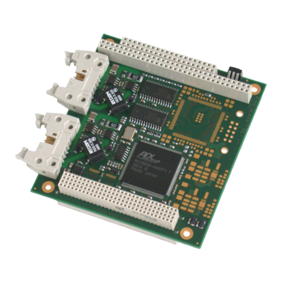
Page 9: Pcb View With Connectors
Overview 1.2 PCB View with Connectors Figure 2: PCB top view of CAN-PCI104/200-2 NOTICE Read chapter “Hardware Installation” on page 10, before you start with the installation of the hardware! See also page 15 for signal assignment of the CAN connectors. -
Page 10: Hardware Installation
(as recommended in PCI-104 specification version 1.0). In the state of delivery the coding switch of the CAN-PCI104/200 is set to “0”, so the module can be operated directly on the host CPU, in slot 1. - Page 11 The CAN-PCI104/200-2 (module with 2 CAN-interfaces) only uses one interrupt on the PCI-Bus as well. Set the position of the coding switch before you mount the CAN-PCI104/200 because it might be difficult to access the coding switch when the module is mounted.
-
Page 12: Technical Data
(10-pin post connector) - CAN-TTL signals (optional) CAN-PCI104/200-1, CAN-PCI104/200-2: 0°C ... +50 °C ambient temperature Temperature range CAN-PCI104/200-2-T: extended temperature range: -40°C ... +75°C ambient temperature Humidity max. 90%, non-condensing according to PCI-104 Specification Version 1.0 (default components layout), Dimensions according to PC/104-Plus Specification Version 2.0 (with optional ISA connector),... -
Page 13: Pc/104-Plus Bus (Only With Optional Isa Connector)
3.3 PC/104-Plus Bus (only with optional ISA Connector) INFORMATION The optional connectors are not equipped in the standard versions. They can be equipped by esd on request. Please state this option in your order. Specification PC/104-Plus Specification Version 2.0 PCI: (according to PCI Spec. -
Page 14: Software Support
- 30 MB free HD drive space - esd CAN driver installed As part of the software development kit (CAN SDK) of the esd NTCAN-API, the tools are contained on the CAN-CD, which is included in delivery of the CAN-PCI104/200. -
Page 15: Connector Assignment
CAN_L, CAN_H ... CAN signals CAN_GND... reference potential of the local CAN physical layer Shield... shield potential - ... reserved for future applications, do not connect! CAN-PCI104/200 Hardware Manual • Doc. No.: C.2046.21 / Rev. 1.1 Page 15 of 29... -
Page 16: Adapter Cable
Adapter Cable 5. Adapter Cable The CAN-PCI104/200-DSUB/10pol. CAN adapter cable (esd order No.: C.2046.70 ) is designed to interface the CAN-PCI104/200 CAN board (or compatible) to a standard CiA ® 303-1 DSUB9 connector. Figure 3: View of the adapter cable... -
Page 17: Assignment Of The Dsub9 Adapter Cable Connector
5.1 Assignment of the DSUB9 Adapter Cable Connector The 9-pin DSUB CAN connector of the adapter cable can be connected to the CAN interfaces of the CAN-PCI104/200. The pin assignment of the DSUB connector is compatible to the recommendations of the CiA DR 303_1, Rev. 1.4. -
Page 18: Correct Wiring Of Electrically Isolated Can Networks
Therefore the practical maximum number of nodes, bus length and stub length are typically much lower. esd has concentrated her recommendations concerning CAN wiring on the specifications of the ISO 11898-2. Thus this wiring hints forgoes to describe the special features of the derived standards CANopen, ARINC825, DeviceNet and NMEA2000. -
Page 19: Light Industrial Environment (Single Twisted Pair Cable)
CAN_H n.c. n.c. CAN_GND n.c. n.c. n.c. n.c. connector case connector case n.c. = not connected earth (FE) Figure 5: CAN wiring for light industrial environment CAN-PCI104/200 Hardware Manual • Doc. No.: C.2046.21 / Rev. 1.1 Page 19 of 29... -
Page 20: Cabling
9-pin DSUB-termination connectors with integrated termination resistor and male and ● female contacts (gender changer) are available from esd (order no. C.1303.01). DSUB termination connectors with male contacts (order no. C.1302.01) or female contacts ● (order no. C.1301.01) and additional functional earth contact are available, if CAN termination and grounding of CAN_GND is required. -
Page 21: Heavy Industrial Environment (Double Twisted Pair Cable)
CAN_L CAN_GND wire shield n.c. n.c. connector case connector case Shield n.c. = not connected earth (FE) Figure 7: CAN wiring for heavy industrial environment CAN-PCI104/200 Hardware Manual • Doc. No.: C.2046.21 / Rev. 1.1 Page 21 of 29... -
Page 22: Device Cabling
DSUB9 connector from ERNI (ERBIC CAN BUS MAX, order no.:154039). The usage of esd’s T-connector type C.1311.03 is not recommended for single shielded double twisted pair cables because the shield potential of the conductive DSUB housing is not looped through this T-connector type. -
Page 23: Electrical Grounding
5000 Table 6: Recommended cable lengths at typical bit rates (with esd-CAN interfaces) Optical couplers are delaying the CAN signals. esd modules typically reach a wire length of ● 37 m at 1 Mbit/s within a proper terminated CAN network without impedance disturbances like e.g. -
Page 24: Examples For Can Cables
Correct Wiring of Electrically Isolated CAN Networks 6.6 Examples for CAN Cables esd recommends the following two-wire and four-wire cable types for CAN network design. These cable types are used by esd for ready-made CAN cables, too. 6.6.1 Cable for light industrial Environment Applications (Two-Wire) -
Page 25: Can Troubleshooting Guide
- there are no open circuits in CAN_H or CAN_L wiring - your bus system has two terminating resistors (one at each end) and that they are 120 Ω each. CAN-PCI104/200 Hardware Manual • Doc. No.: C.2046.21 / Rev. 1.1 Page 25 of 29... -
Page 26: Electrical Grounding
(see figure at previous page). 4. Measure the DC voltage between CAN_L and CAN_GND (see figure at previous page). Normally the voltage should be between 2.0 V and 3.0 V. Page 26 of 29 Hardware Manual • Doc. No.: C.2046.21 / Rev. 1.1 CAN-PCI104/200... -
Page 27: Can Transceiver Resistance Test
If you have executed the fault diagnostic steps of this troubleshooting guide and you even can not find a solution for your problem our support department will be able to assist. Please contact our support via email at support@esd.eu or by phone +40-511-37298-130. CAN-PCI104/200 Hardware Manual •... -
Page 28: Order Information
- also available as PC104+ with ISA and PCI connector (on request) CAN-PCI104/200-2 As C.2046.02 but with 2 CAN 2.0A/B interfaces C.2046.04 CAN-PCI104/200-2-T Passive PCI104 to CAN interface board for an extended C.2046.08 temperature range from -40°C up to +75°C, - SJA1000 CAN controller - 2 CAN 2.0A/B interface - physical layer according to ISO 11898, electrically isolated;... - Page 29 Order Information PDF Manuals Manuals are available in English and usually in German as well. For availability of English manuals see table below. Please download the manuals as PDF documents from our esd website www.esd.eu for free. Manuals Order No.
Need help?
Do you have a question about the CAN-PCI104/200 and is the answer not in the manual?
Questions and answers