Table of Contents
Advertisement
Quick Links
CAN-PCI/266
Passive 66-MHz
PCI-CAN Interface
Hardware Manual
to Product C.2036.02, C.2036.04
CAN-PCI/266
Hardware Manual • Doc. No.: C.2036.21 / Rev. 1.5
Page 1 of 26
esd electronic system design gmbh
Vahrenwalder Str. 207 • 30165 Hannover • Germany
http://www.esd.eu
Phone: +49 (0) 511 3 72 98-0 • Fax: +49 (0) 511 3 72 98-68
Advertisement
Table of Contents

Related Manuals for ESD CAN-PCI/266


Summary of Contents for ESD CAN-PCI/266
- Page 1 CAN-PCI/266 Hardware Manual • Doc. No.: C.2036.21 / Rev. 1.5 Page 1 of 26 esd electronic system design gmbh Vahrenwalder Str. 207 • 30165 Hannover • Germany http://www.esd.eu Phone: +49 (0) 511 3 72 98-0 • Fax: +49 (0) 511 3 72 98-68...
- Page 2 The information in this document has been carefully checked and is believed to be entirely reliable. esd makes no warranty of any kind with regard to the material in this document, and assumes no responsibility for any errors that may appear in this document. In particular descriptions and technical data specified in this document may not be constituted to be guaranteed product features in any legal sense.
- Page 3 Date of print: 2015-11-23 Document type DOC0800 number: Hardware version: CAN-PCI/266 Rev. 1.0 Document History The changes in the document listed below affect changes in the hardware as well as changes in the description of the facts, only. Revision Chapter...
-
Page 4: Safety Instructions
● Do not operate the CAN-PCI/266 adjacent to heat sources and do not expose it to unnecessary thermal radiation. Ensure an ambient temperature as specified in the technical data. ● Do not use damaged or defective cables to connect the CAN-PCI/266 and follow the CAN wiring hints in chapter: "Correctly Wiring Electrically Isolated CAN Networks". -
Page 5: Table Of Contents
7.1 Termination.......................... 22 Electrical Grounding......................23 Short Circuit in CAN Wiring....................23 CAN_H/CAN_L-Voltage ......................23 CAN Transceiver Resistance Test..................24 Support by esd........................24 Declaration of Conformity......................25 Order Information........................26 CAN-PCI/266 Hardware Manual • Doc. No.: C.2036.21 / Rev. 1.5 Page 5 of 26... -
Page 6: Overview
The CAN-PCI/266 is a passive PCI-bus board for 66 MHz PCI-bus systems with one or optional two CAN-interfaces. The CAN-PCI/266 works with a bus width of 32 bits. The module can also be used in 33 MHz PCI-bus systems at a bus speed of 33 MHz. -
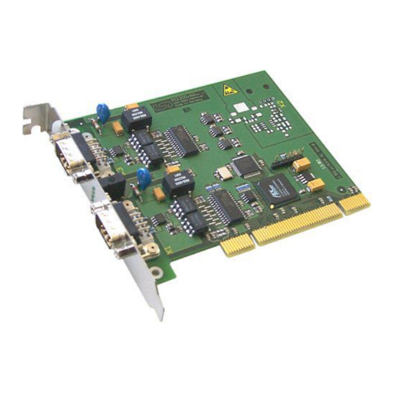
Page 7: Pcb View With Connectors
1.2 PCB View with Connectors Figure 2: Top layer view of the module with 2x CAN See also page 13 for signal assignment of the CAN connectors. CAN-PCI/266 Hardware Manual • Doc. No.: C.2036.21 / Rev. 1.5 Page 7 of 26... -
Page 8: Hardware Installation
Hazardous Voltage - Risk of electric shock due to unintentional contact with uninsulated live parts with high voltages inside of the system into which the CAN-PCI/266 is to be integrated. Never carry out work while power supply voltage is switched on! ATTENTION Electrostatic discharges may cause damage to electronic components. - Page 9 11. Switch on the computer and the peripheral devices. 12. End of hardware installation. Continue with the software installation as described in the manual ‘CAN-API, Installation Guide’. CAN-PCI/266 Hardware Manual • Doc. No.: C.2036.21 / Rev. 1.5 Page 9 of 26...
-
Page 10: Technical Data
33 MHz / 3.3 V or 5.0 V signalling level Controller PLX PCI9056 Interrupt Interrupt Signal A no restrictions for the position of the CAN-PCI/266 on the PCI bus, PCI Slot position bridges are tolerated Board dimensions compatible with all 'short' PCI-card slots... -
Page 11: Can Interface
“NTCAN-API Part 1: Structure, Function and C/C++ API” Application Developers Manual and “NTCAN-API Part 2: Installation, Configuration and Firmware Update” Installation Guide esd-order No.: C.2001.21 CAN-PCI/266 Hardware Manual • Doc. No.: C.2036.21 / Rev. 1.5 Page 11 of 26... -
Page 12: Front Panel View With Led-Display
4. Front Panel View with LED-Display The CAN-PCI-266 is equipped with four green LEDs in the front panel. CAN Net 1 only LED 420A: reserved CAN-PCI/266-2 LED 420B: CAN-IRQ1 LED 420C: CAN-IRQ0 LED 420D: power supply CAN Net 0 Figure 3: Front panel view... -
Page 13: Connector Assignments
CAN physical layer Shield ... shielding (connected with the case of the 9-pin DSUB connector) reserved ... reserved for future applications, do not connect! CAN-PCI/266 Hardware Manual • Doc. No.: C.2036.21 / Rev. 1.5 Page 13 of 26... -
Page 14: Option: Devicenet-Interface
= 24 V ± 4%) V-... reference potential to V+ and to CAN+/CAN- CAN+, CAN-... CAN-signals Shield... Shielding (via high resistance RC combination connected to earth (shield panel)) Page 14 of 26 Hardware Manual • Doc. No.: C.2036.21 / Rev. 1.5 CAN-PCI/266... -
Page 15: Correctly Wiring Electrically Isolated Can Networks
Therefore the practical maximum number of nodes, bus length and stub length are typically much lower. esd has concentrated her recommendations concerning CAN wiring on the specifications of the ISO 11898-2. Thus this wiring hints forgoes to describe the special features of the derived standards CANopen, ARINC825, DeviceNet and NMEA2000. -
Page 16: Heavy Industrial Environment (Double Twisted Pair Cable)
6.2 Heavy Industrial Environment (Double Twisted Pair Cable) 6.2.1 General Rules NOTICE esd only grants the compliance with directive 2014/30/EU, if the CAN wiring is carried out with single shielded double twisted pair cables that match the requirements of ISO 11898-2. -
Page 17: Device Cabling
DSUB9 connector from ERNI (ERBIC CAN BUS MAX, order no.:154039). The usage of esd’s T-connector type C.1311.03 is not recommended for single shielded double twisted pair cables because the shield potential of the conductive DSUB housing is not looped through this T-connector type. -
Page 18: Light Industrial Environment (Single Twisted Pair Cable)
6.3.1 General Rules NOTICE esd only grants the compliance with directive 2014/30/EU, if the CAN wiring is carried out with single shielded double twisted pair cables that match the requirements of ISO 11898-2. See previous chapter: 'Heavy Industrial Environment (Double Twisted Pair Cable)'. -
Page 19: Cabling
9-pin DSUB-termination connectors with integrated termination resistor and male and ● female contacts (gender changer) are available from esd (order no. C.1303.01). DSUB termination connectors with male contacts (order no. C.1302.01) or female contacts ● (order no. C.1301.01) and additional functional earth contact are available, if CAN termination and grounding of CAN_GND is required. -
Page 20: Electrical Grounding
5000 Table 5: Recommended cable lengths at typical bit rates (with esd-CAN interfaces) Optical couplers are delaying the CAN signals. esd modules typically reach a wire length of ● 37 m at 1 Mbit/s within a proper terminated CAN network without impedance disturbances like e.g. -
Page 21: Examples For Can Cables
Correctly Wiring Electrically Isolated CAN Networks 6.6 Examples for CAN Cables esd recommends the following two-wire and four-wire cable types for CAN network design. These cable types are used by esd for ready-made CAN cables, too. 6.6.1 Cable for light industrial Environment Applications (Two-Wire) -
Page 22: Can Troubleshooting Guide
- there are no open circuits in CAN_H or CAN_L wiring - your bus system has two terminating resistors (one at each end) and that they are 120 Ω each. Page 22 of 26 Hardware Manual • Doc. No.: C.2036.21 / Rev. 1.5 CAN-PCI/266... -
Page 23: Electrical Grounding
(see figure at previous page). 4. Measure the DC voltage between CAN_L and CAN_GND (see figure at previous page). Normally the voltage should be between 2.0 V and 3.0 V. CAN-PCI/266 Hardware Manual • Doc. No.: C.2036.21 / Rev. 1.5 Page 23 of 26... -
Page 24: Can Transceiver Resistance Test
If you have executed the fault diagnostic steps of this troubleshooting guide and you even can not find a solution for your problem our support department will be able to assist. Please contact our support via email at support@esd.eu or by phone +40-511-37298-130. Page 24 of 26 Hardware Manual •... -
Page 25: Declaration Of Conformity
Declaration of Conformity 8. Declaration of Conformity CAN-PCI/266 Hardware Manual • Doc. No.: C.2036.21 / Rev. 1.5 Page 25 of 26... -
Page 26: Order Information
Table 6: Order information PDF Manuals Manuals are available in English and usually in German as well. For availability of English manuals see table below. Please download the manuals as PDF documents from our esd website www.esd.eu for free. Manuals Order No.
Need help?
Do you have a question about the CAN-PCI/266 and is the answer not in the manual?
Questions and answers