Table of Contents
Advertisement
Quick Links
CAN-PCI/405-B4
PCI-CAN Interface
Hardware Manual
to Product C.2041.04
CAN-PCI/405-B4
Hardware Manual • Doc. No.: C.2041.21 / Rev. 1.2
Page 1 of 29
esd electronic system design gmbh
Vahrenwalder Str. 207 • 30165 Hannover • Germany
http://www.esd.eu
Phone: +49 (0) 511 3 72 98-0 • Fax: +49 (0) 511 3 72 98-68
Advertisement
Table of Contents

Related Manuals for ESD CAN-PCI/405-B4


Summary of Contents for ESD CAN-PCI/405-B4
- Page 1 CAN-PCI/405-B4 Hardware Manual • Doc. No.: C.2041.21 / Rev. 1.2 Page 1 of 29 esd electronic system design gmbh Vahrenwalder Str. 207 • 30165 Hannover • Germany http://www.esd.eu Phone: +49 (0) 511 3 72 98-0 • Fax: +49 (0) 511 3 72 98-68...
- Page 2 The information in this document has been carefully checked and is believed to be entirely reliable. esd makes no warranty of any kind with regard to the material in this document, and assumes no responsibility for any errors that may appear in this document. In particular descriptions and technical data specified in this document may not be constituted to be guaranteed product features in any legal sense.
- Page 3 Safety informations inserted 'Electrical Isolation' entry revised Chapter revised 2014-06-25 5.1.1 Table revised and note about the wiring of the CAN-PCI/405-B4-1C4 inserted Declaration of Conformity updated Chapter 'Order Information' moved and revised Technical details are subject to change without further notice. CAN-PCI/405-B4 Hardware Manual •...
- Page 4 ● Do not operate the CAN-PCI/405-B4 adjacent to heat sources and do not expose it to unnecessary thermal radiation. Ensure an ambient temperature as specified in the technical data. ● Do not use damaged or defective cables to connect the CAN-PCI/405-B4 and follow the CAN wiring hints in chapter: "Correctly Wiring Electrically Isolated CAN Networks".
-
Page 5: Table Of Contents
Guide.......................24 7.1 Termination.......................... 24 Electrical Grounding......................25 Short Circuit in CAN Wiring....................25 CAN_H/CAN_L-Voltage ......................25 CAN Transceiver Resistance Test ..................26 Declaration of Conformity......................27 Order Information........................28 CAN-PCI/405-B4 Hardware Manual • Doc. No.: C.2041.21 / Rev. 1.2 Page 5 of 29... -
Page 6: Overview
Figure 1: Block circuit diagram of the CAN-PCI/405-B4 The CAN-PCI/405-B4 is a PC board designed for the PCI bus. It supports four independent CAN interfaces. The four CAN interfaces can be connected via the 37-pole DSUB panel connector in the slot bracket. -
Page 7: Hardware Installation
Carefully push the board down until it snaps into place. Attach the board. Secure the cover with the according screws at the back of the PC. CAN-PCI/405-B4 Hardware Manual • Doc. No.: C.2041.21 / Rev. 1.2 Page 7 of 29... - Page 8 Secure the cover with the according screws at the back of the PC. Connect the CAN wire. Please note that the CAN bus has to be terminated at both ends! esd offers special T- connectors and terminator connectors. Additionally the CAN_GND signal has to be connected to earth at exactly one point.
-
Page 9: Pcb View And Led Description
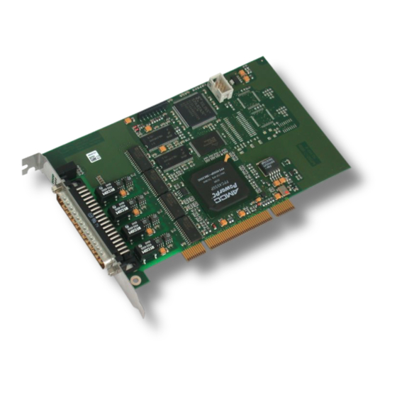
PCB View and LED Description 3. PCB View and LED Description 3.1 PCB View Figure 2: PCB top view of CAN-PCI/405-B4 See also page 14 for signal assignment of the CAN connector. CAN-PCI/405-B4 Hardware Manual • Doc. No.: C.2041.21 / Rev. 1.2... -
Page 10: Leds And Dsub37 Connector In The Slot Bracket
PCB View and LED Description 3.2 LEDs and DSUB37 Connector in the Slot Bracket Four CAN nets can be connected to the CAN-PCI/405-B4 card via the 37-pole DSUB panel connector in the slot bracket. Figure 3: LEDs and connector position... -
Page 11: Technical Data
Dimensions 164.64 mm x 106.68 mm (without slot cover panel and CAN connector) Weight approx. 130 g Table 2: General data of the CAN-PCI/405-B4 4.2 Microprocessor and Memory PowerPC 405GP, 200 MHz, 32 bit Flash EPROM 2 MB Flash EPROM... -
Page 12: Pci Bus
CAN interfaces are electrically isolated via optocouplers and DC/DC- interface against converters against each other and against the PCIe bus potentials other units Table 5: Data of the CAN interface Page 12 of 29 Hardware Manual • Doc. No.: C.2041.21 / Rev. 1.2 CAN-PCI/405-B4... -
Page 13: Software Support
For detailed information about the driver availability for your special operating system, please contact our sales team: sales@esd.eu Additional free-of-charge esd CAN tools for Windows offer efficient setup and analysis of CAN applications and networks. The software installation and the software drivers are described in the manual:... -
Page 14: Connector Assignments
CANx_L, CANx_H ... CAN signal lines of the CAN interfaces (x= 0 … 3) CAN_GND ... reference potential of the local CAN physical layer (x= 0 … 3) n.c..not connected Page 14 of 29 Hardware Manual • Doc. No.: C.2041.21 / Rev. 1.2 CAN-PCI/405-B4... -
Page 15: Adapter Cable Can-Pci405-B4-1C4
Connector Assignments 5.1.1 Adapter Cable CAN-PCI405-B4-1C4 The adapter cable CAN-PCI/405-B4-1C4 is designed for the connection to the 37-pole DSUB panel connector (male) of the CAN-PCI/405-B4. The signals of the four CAN interfaces are conducted to four DSUB9 plugs (male). Total lenght:... - Page 16 The CAN-GND signals of the cables of the 4-channel cable adapter "CAN-PCI/405-B4- 1C4" are connected via the wire shield if the adapter is connected to the esd hardware. Thus the housings of the 9-pin DSUB connectors are connected to the respective CAN-GND, because no other potential is available on these connectors.
- Page 17 Signal Description: CAN_L, CAN_H ... CAN signal lines CAN_GND ... reference potential of the local CAN physical layer reserved ... reserved for future applications, do not connect! CAN-PCI/405-B4 Hardware Manual • Doc. No.: C.2041.21 / Rev. 1.2 Page 17 of 29...
-
Page 18: Correctly Wiring Electrically Isolated Can Networks
6.1.1 General Rules Note: esd grants the EC Conformity of the product, if the CAN wiring is carried out with at least single shielded single twisted pair cables that match the requirements of ISO 11898-2. Single shielded double twisted pair cable wiring as described in chapter 6.2. -
Page 19: Cabling
If the used CAN interface is not equipped with an integrated CAN termination and it is at an ● end of the bus, use external termination plugs. 9-pin DSUB-termination connectors with male and female contacts and earth terminal are ● available as accessories CAN-PCI/405-B4 Hardware Manual • Doc. No.: C.2041.21 / Rev. 1.2 Page 19 of 29... -
Page 20: Heavy Industrial Environment (Double Twisted Pair Cable)
CAN_L CAN_GND wire shield n.c. n.c. connector case connector case Shield n.c. = not connected earth (FE) Figure 7: CAN wiring for heavy industrial environment Page 20 of 29 Hardware Manual • Doc. No.: C.2041.21 / Rev. 1.2 CAN-PCI/405-B4... -
Page 21: Device Cabling
DSUB9 connector from ERNI (ERBIC CAN BUS MAX, order no.:154039). The usage of esd’s T-connector type C.1311.03 is not recommended for single shielded double twisted pair cables because the shield potential of the conductive DSUB housing is not looped through this T-connector type. -
Page 22: Electrical Grounding
Earthing can e.g. be made at a connector/T-connector. ● 6.4 Bus Length Optical couplers are delaying the CAN signals. esd modules typically reach a wire length of ● 37 m at 1 Mbit/s within a closed net without impedance disturbances like e.g. cable stubs >>... -
Page 23: Examples For Can Cables
Äußerer Eichwald 74535 Mainhardt BUS-Schleppflex-PUR-C (2x 2x 0.25 mm²) Order No.: 94 025 026 (UL appr.) Germany www.concab.de Note: Configured CAN cables can be ordered from esd. CAN-PCI/405-B4 Hardware Manual • Doc. No.: C.2041.21 / Rev. 1.2 Page 23 of 29... -
Page 24: Can Troubleshooting Guide
- there are no open circuits in CAN_H or CAN_L wiring - your bus system has two terminating resistors (one at each end) and that they are 120 Ω each. Page 24 of 29 Hardware Manual • Doc. No.: C.2041.21 / Rev. 1.2 CAN-PCI/405-B4... -
Page 25: Electrical Grounding
Stop all network communication. Measure the DC voltage between CAN_H and GND (see figure above). Measure the DC voltage between CAN_L and GND (see figure above). CAN-PCI/405-B4 Hardware Manual • Doc. No.: C.2041.21 / Rev. 1.2 Page 25 of 29... -
Page 26: Can Transceiver Resistance Test
Another sign for a faulty transceiver is a very high deviation between the two measured input resistance (>> 200%). CAN node CAN_H CAN_L transceiver CAN_GND disconnect Power CAN! disconnect power! Figure 11: Measuring the internal resistance of CAN transceivers Page 26 of 29 Hardware Manual • Doc. No.: C.2041.21 / Rev. 1.2 CAN-PCI/405-B4... -
Page 27: Declaration Of Conformity
Declaration of Conformity 8. Declaration of Conformity CAN-PCI/405-B4 Hardware Manual • Doc. No.: C.2041.21 / Rev. 1.2 Page 27 of 29... -
Page 28: Order Information
Table 8: Order information PDF Manuals Manuals are available in English and usually in German as well. For availability of English manuals see table below. Please download the manuals as PDF documents from our esd website www.esd.eu for free. Page 28 of 29 Hardware Manual •... - Page 29 Order Information Manuals Order No. CAN-PCI/405-B4-ME Hardware manual in English C.2041.21 NTCAN-API: Application Developers Manual CAN-API-ME C.2001.21 NTCAN-API: Driver Installation Guide CANopen-ME CANopen Manager/Slave Manual C.2002.21 J1939 Software Manual J1989 Software Manual in English C.1130.21 Table 9: Available manuals Printed Manuals If you need a printout of the manual additionally, please contact our sales team: sales@esd.eu...
Need help?
Do you have a question about the CAN-PCI/405-B4 and is the answer not in the manual?
Questions and answers