
Related Manuals for CNC4PC C25


Summary of Contents for CNC4PC C25
- Page 1 USER’S MANUAL VER.3.2 C25- SMOOTH STEPPER LPT BOARD Rev. 5 JUN, 2019 ___________________________________________________________________________ User’s Manual Page i...
-
Page 2: Table Of Contents
USER'S MANUAL TABLE OF CONTENTS Contents Page # FEATURES ........................1 SPECIFICATIONS ......................1 FUNCTIONAL BLOCK DIAGRAMS ................2 Inputs 10, 11, 12 13 and 15 (Port 1 and Port 2) Schematic ........2 Inputs 2-9 (Port 2) Schematic ..................2 POWERING THE BOARD .................... -
Page 3: Features
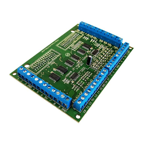
FEATURES • 34 Inputs and Outputs on 2 ports. • Full access to all the pins of the Smooth Stepper Board. • Connects directly to the Smooth Stepper (from Warp9). The board is provided with sockets that allow the Smooth Stepper Board to be plugged directly into this board. -
Page 4: Functional Block Diagrams
This eliminates the high frequency components of the noise generating a fast changing signal. Outputs 1, 14, 16 and 17 (Port 1 and 2) and outputs 2-9 (port 1). All those pins are directly wired to the C25 output terminals. User’s Manual Page 2... -
Page 5: Powering The Board
This board is designed to get its power from the Smooth Stepper. The Smooth Stepper has jumpers next to the IDC26 connector on which the C25 connects to that need to be closed in order to send +5vdc to pin 26 of each IDC26 connector to power the C25. -
Page 6: Connecting Switches Or Push Button
Connecting Switches or push button. WIRING DIAGRAM TO CONNECT SWITCHES Note: When you measure the voltage of the pin in the air after the resistor, you may find the voltage to be higher, but once it interacts with the pull-down in the input pin of the breakout board, it stabilizes to +5vdc. - Page 7 WIRING DIAGRAM TO CONNECT IN PARALLEL NPN OPEN COLLECTOR PROXIMITY SENSORS Connecting NPN open collector proximity sensor with the C25 R1 Value (12V) R1 Value (24V) Approx. 10KΩ Approx. 25KΩ Wiring diagram to connect NPN proximity sensors with internal pull up resistor Some NPN proximity sensors have an internal pull-up resistor (R1).
-
Page 8: Connecting Pnp Sensors (For Any Input)
Note. R value has to be known to do this operation. A 4.7KOhm@1/2W is recommended. Connecting PNP sensors (For any input) Wiring diagram to connect PNP proximity sensors Connecting PNP proximity sensor with the C25 R Value (12V) R Value (24V) Approx. 10KΩ... -
Page 9: Dimensions
DIMENSIONS All dimensions are in Millimeters. Fixing holes (3.8mm). DISCLAIMER Use caution. CNC machines can be dangerous machines. Neither DUNCAN USA, LLC nor Arturo Duncan are liable for any accidents resulting from the improper use of these devices. This product is not a fail-safe device and it should not be used in life support systems or in other devices where its failure or possible erratic operation could cause property damage, bodily injury or loss of life.
Need help?
Do you have a question about the C25 and is the answer not in the manual?
Questions and answers