Table of Contents
Advertisement
Quick Links
Advertisement
Table of Contents

Subscribe to Our Youtube Channel
Related Manuals for UTEPO UTP7624GE-PoE-P


Summary of Contents for UTEPO UTP7624GE-PoE-P
- Page 1 High-power fanless PoE switch (24GE PoE+4*10G SFP L3-managed) Quick Setup Wizard...
-
Page 2: Table Of Contents
Content 1 Product Introduction Overview Product Feature Board Diagram Specification Installation Shipping List Installation Precautions 2.2.1 Safety Precautions 2.2.2 Installation Requirements The Requirements of Electromagnetic Environment 2.2.3 Installation Way 2.3.1 Rack Installation 2.3.2 Workbench Installation 2.3.3 Wall-hung Installation Cable Connection 2.4.1 Device Connection 2.4.2... -
Page 3: Product Introduction
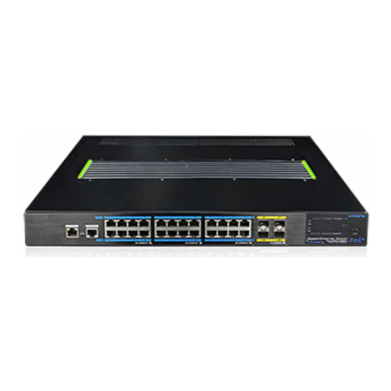
1 Product Introduction 1.3 Board Diagram AC power supply 1.1 Overview The High-power fanless PoE switch(24 ports gigabit PoE L3-managed),which provide 24*10/100/1000 RJ45 ports,4* 1000/10G uplink SFP slots ,supports fanless high-power PoE output, support static layer-3 routing network management, 4*one-key smart mode and PoE management . The Products are widely used in security surveillance, network engineering projects, especially in low noise surround such as hotel, office, hospital and so on. -
Page 4: Specification
1.4 Specification 2 Installation Item PoE switch Power Supply AC power supply Caution Power Voltage Range AC 100~240V 50/60Hz Auto-sensing Consumption Self consumption:30W, PoE output:350W max Anti-counterfeiting label is attached to switch's cover. Product damage Copper ports: 10/100/1000Mbps adaptive caused by unauthorized disassembly is not covered under warranty. RJ45 ports support IEEE 802.3 af/at Ethernet Port SFP ports:1000/10GBase-X SFP port(Mini-GBIC) -
Page 5: Installation Requirements
2.2.3 The Requirements of Electromagnetic Environment Instruction When it is working, the switch may be affected by external interference outside Some area in the switch maybe very hot. Please be careful to the system through the ways of radiation and conduction. Please pay attention touch, be careful to burn. -
Page 6: Workbench Installation
(3) Put the device on the rack’s bracket and move the rack along the slot to proper position ; Instruction Use screws to fit the installation hanger at rack’s fixed slot, make sure the The distance betweed the above switch and the below switch must be device is installed at rack’s bracket steadily. -
Page 7: Cable Connection
3 Function Configuration Guide 2.4 Cable Connection 2.4.1 Device Connection 3.1 Computer Requirements U s e c r o s s n e t w o r k c a b l e o r c r o s s - o v e r c a b l e t o c o n n e c t P C o r other device with switch's Ethernet port;... -
Page 8: Web Page Configuration Guide
Web Page Configuration Guide After inputting the correct password, click <Login in>, the browser will display the product Web management page. The browser version recommend:IE7 and later, Firefox browser, Chrome, 360 browser (IE7 and later). 3.3.2 One-key smart introduction 3.3.1 Start and Login This product web default IP address: 1 9 2 . -
Page 9: Change Language
(2) 4* One-key smart web operation (4) Advance settings User can operate the one-key smart mode on and off on the web. click the CCTV\LOCK\RING\ONLINE icon,the mode is on. Then click second time,the mode is off.The mode status is synchronized with the switch panal. - Page 10 Environment protection This product design is environmental friendly and the product should be stored, used and dicarded in accordance with relevant national legal / regulatory requirements.
Need help?
Do you have a question about the UTP7624GE-PoE-P and is the answer not in the manual?
Questions and answers