Table of Contents
Advertisement
Quick Links
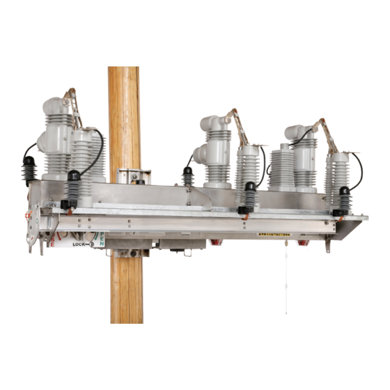
IntelliRupter
®
PulseCloser
Outdoor Distribution (15.5 kV, 27 kV, and 38 kV)
Table of Contents
Section
Qualified Persons . . . . . . . . . . . . . . . . . . . . . . . . . . . 2
Read this Instruction Sheet . . . . . . . . . . . . . . . . . . . 2
Retain this Instruction Sheet . . . . . . . . . . . . . . . . . . . 2
Proper Application . . . . . . . . . . . . . . . . . . . . . . . . . . 2
Special Warranty Provisions . . . . . . . . . . . . . . . . . . . 3
Understanding Safety-Alert Messages . . . . . . . . . . . 4
Following Safety Instructions . . . . . . . . . . . . . . . . . . 4
Replacement Instructions and Labels . . . . . . . . . . . 4
. . . . . . . . . . . . . . . . . . . . . . . . . 5
. . . . . . . . . . . . . . . . . . . . . . . . . . . . . . . . . . . 6
May 9, 2022
© S&C Electric Company 2020-2022, all rights reserved
®
Fault Interrupter
R3 Communication Module
Retrofit and Configuration
Page
. . . . . . . . . . . . 7
Section
Tools Required . . . . . . . . . . . . . . . . . . . . . . . . . . . . . 8
Removing the Radio Tray . . . . . . . . . . . . . . . . . . . . . 8
Removing the R0 Wi-Fi/GPS Module . . . . . . . . . . . . 9
Installing the R3 Wi-Fi/GPS Module . . . . . . . . . . . . .10
Reinstalling the Radio Tray . . . . . . . . . . . . . . . . . . . .12
. . . . . . . . . . . . . . . . . . . . . . . . . . . . . . .15
. . . . . . . . . . . . . . . . . . . . . . . . . . . .18
Instruction Sheet 766-526
Page
. . . . . . . . . . . . . . . . . . .13
. . . . . . .16
Advertisement
Table of Contents

Related Manuals for S&C IntelliRupter PulseCloser R3


Summary of Contents for S&C IntelliRupter PulseCloser R3
-
Page 1: Table Of Contents
IntelliRupter ® PulseCloser ® Fault Interrupter Outdoor Distribution (15.5 kV, 27 kV, and 38 kV) R3 Communication Module Retrofit and Configuration Table of Contents Section Page Section Page Introduction Communication Module Retrofit Qualified Persons . . . . . . . . . . . . . . . . . . . . . . . . . . . 2 Tools Required . -
Page 2: Introduction
Introduction Qualified Persons WARNING The equipment covered by this publication must be installed, operated, and maintained by qualified persons who are knowledgeable in the installation, operation, and maintenance of overhead electric power distribution equipment along with the associated hazards . A qualified person is one who is trained and competent in: •... -
Page 3: Special Warranty Provisions
Introduction Special Warranty The standard warranty contained in S&C’s standard conditions of sale, as set forth in Price Sheets 150 and 181, applies to the IntelliRupter fault interrupter, except that the Provisions first paragraph of the said warranty is replaced by the following: (1) General: The seller warrants to the immediate purchaser or end user for a period of 10 years from the date of shipment that the equipment delivered will be of the kind and quality specified in the contract description and will be free of defects... -
Page 4: Safety Information
Safety Information Understanding Several types of safety-alert messages may appear throughout this instruction sheet and on labels attached to the IntelliRupter PulseCloser Fault Interrupter. Familiarize Safety-Alert Messages yourself with these types of messages and the importance of these various signal words: DANGER “DANGER”... -
Page 5: Safety Precautions
Safety Precautions DANGER IntelliRupter PulseCloser Fault Interrupters operate at high voltage. Failure to observe the precautions below will result in serious personal injury or death. Some of these precautions may differ from your company’s operating procedures and rules . Where a discrepancy exists, follow your company’s operating procedures and rules . -
Page 6: Overview
Overview S&C products may be revised to add new features to an existing assembly. The revision information is listed after the catalog number with “R” and the revision number. Parts required for a specific revision are also refered to with the same Rx designation. -
Page 7: Communication Module Removal
Communication Module Removal The communication module can be easily removed and replaced from a bucket truck using a hookstick. NOTICE To prevent contamination of the connectors, never place the connector on the ground without some form of protection from dirt and mud . Removing the communication module can be done from a bucket truck with the module handling fitting, catalog number 4450, attached to a suitable hookstick. -
Page 8: Communication Module Retrofit
Communication Module Retrofit Tools Required: • Nut driver, ¼-inch Battery • Nut driver, ⅜-inch cover • Phillips screwdriver, medium • Flat-head screwdriver, medium • Diagonal wire cutter (to cut or trim cable ties) • SCS 8501 Static Dissipative Mat Removing the Radio Tray Follow these steps to remove the radio tray assembly from the communication module: Loosen the battery compartment cover locking... -
Page 9: Removing The R0 Wi-Fi/Gps Module
Communication Module Retrofit Removing the R0 Wi-Fi/GPS Module Wi-Fi antenna cable GPS antenna cable The R0 Wi-Fi/GPS module, with connections for power, Connector data, and antenna, is mounted on the side of the radio tray. See Figure 7. Follow these steps to remove the R0 Wi-Fi/GPS module circuit board. -
Page 10: Installing The R3 Wi-Fi/Gps Module
Communication Module Retrofit Installing the R3 Wi-Fi/GPS Module Follow these steps to install the R3 Wi-Fi/GPS module. STEP 1. Fold the harness that was connected to the R0 circuit board as shown in Figure 10 and secure it with the indicated cable ties. STEP 2. - Page 11 Communication Module Retrofit STEP 6. Attach cables to the Wi-Fi/GPS module. See Figure 14. (a) The two antenna connectors are marked for “GPS” and “Wi-Fi.” Connect them as indicated. (b) The three gray cables are marked for the appropriate connector. Connect them from top to bottom in this order: J18, J17, and J16.
-
Page 12: Reinstalling The Radio Tray
Communication Module Retrofit Connecting the cables as instructed in this step emulates operation of the R0 Communica- tion Module, which is a serial communication configuration. For Ethernet IP configuration, go to the “Setting the R3 Communication Mod- ule for Ethernet IP Configuration” section on page 13. -
Page 13: Setting The R3 Communication Module To Ethernet Ip Configuration
Setting the R3 Communication Module to Ethernet IP Configuration NOTICE Ethernet 1 Proper grounding with a wrist strap connected to ground is required when touching any components within the communication module or contacts on the R3 Communication Module connector . The R3 Communication Module is shipped from the factory with a serial communication configuration. - Page 14 Setting the R3 Communication Module to Ethernet IP Configuration STEP 7. Use the R3 Communication Module Web interface to reassign the existing IntelliRupter fault interrupter control module IP address setpoint to the R3 Communication Module Ethernet 2 interface Static IP address setting. See S&C Instruction Sheet 766-528, when using communication module firmware version 3.0.00512 and later, and S&C Instruction Sheet...
-
Page 15: Inserting The Communication Module Into The Base
Inserting the Communication Module Into the Base The communication module can be installed from a bucket truck with the module handling fitting, catalog number 4450, attached to a suitable hookstick. CAUTION The communication module is heavy, weighing more than 26 pounds (12 kg). S&C does not recommend removal and replacement from the ground using an extendostick . -
Page 16: Wi-Fi/Gps Board Configuration Details
Wi-Fi/GPS Board Configuration Details J15 - Not Used J13 - Not Used J17 - GPS pulse J6 - RJ45 Ethernet 2 - Wi-Fi/GPS board to radio J16 - Wi-Fi serial J1 - RJ45 Ethernet 1 - Wi-Fi/GPS board to control J15 - serial J2 - Power J12 - GPS antenna coax to control... - Page 17 Wi-Fi/GPS Board Configuration Details The R3 Communication Module Ethernet ports use RJ-45 connectors with the pinout shown in Figure 25. They are auto-sensing for assignment of transmit and receive lines (no crossover cables required) and auto-negotiate for 10-Mbps or 100-Mbps data rates, as required by the Function Description connected device.
-
Page 18: Wiring Diagrams
Wiring Diagrams Figure 26. The wiring diagram before Ethernet IP configuration. S&C Instruction Sheet 766-526... - Page 19 Wiring Diagrams Figure 27. The wiring diagram after Ethernet IP configuration. S&C Instruction Sheet 766-526...
Need help?
Do you have a question about the IntelliRupter PulseCloser R3 and is the answer not in the manual?
Questions and answers