Table of Contents
Advertisement
Vista
SD Underground Distribution Switchgear
®
Outdoor Distribution (17.5 kV and 29 kV)
Table of Contents
Section
Qualified Persons . . . . . . . . . . . . . . . . . . . . . . . . . . . 2
Read this Instruction Sheet . . . . . . . . . . . . . . . . . . . 2
Retain this Instruction Sheet. . . . . . . . . . . . . . . . . . . 2
Proper Application . . . . . . . . . . . . . . . . . . . . . . . . . . 2
Warranty . . . . . . . . . . . . . . . . . . . . . . . . . . . . . . . . . . 3
Warranty Qualifications . . . . . . . . . . . . . . . . . . . . . . 3
Understanding Safety-Alert Messages . . . . . . . . . . . 4
Following Safety Instructions . . . . . . . . . . . . . . . . . . 4
Replacement Instructions and Labels . . . . . . . . . . . 4
Single-Way Vault-Mounted Style . . . . . . . . . . . . . 5
Multi-Way Vault-Mounted Style . . . . . . . . . . . . . . 6
Pad-Mounted Style . . . . . . . . . . . . . . . . . . . . . . . 7
. . . . . . . . . . . . . . . . . . . . . . . . . 8
Packing . . . . . . . . . . . . . . . . . . . . . . . . . . . . . . . . . . . 9
Inspection . . . . . . . . . . . . . . . . . . . . . . . . . . . . . . . . . 9
Handling . . . . . . . . . . . . . . . . . . . . . . . . . . . . . . . . . .10
February 1, 2021
© S&C Electric Company 2014-2021, all rights reserved
With Visi-Gap
Switches and Visi-Gap
Fault Interrupters
Installation
Page
Section
Installation
Switchgear Placement . . . . . . . . . . . . . . . . . . . . .12
Installed Through 31½-Inch Manhole . . . . . . . . .13
Cables . . . . . . . . . . . . . . . . . . . . . . . . . . . . . . . . .14
Grounding . . . . . . . . . . . . . . . . . . . . . . . . . . . . . .15
Fault Indicators . . . . . . . . . . . . . . . . . . . . . . . . . . .15
Switchgear Placement . . . . . . . . . . . . . . . . . . . . .16
Access to Interior . . . . . . . . . . . . . . . . . . . . . . . . .16
Cables . . . . . . . . . . . . . . . . . . . . . . . . . . . . . . . . .18
Attach Hinged-Roof Counterweights . . . . . . . . . 20
Cover Panels . . . . . . . . . . . . . . . . . . . . . . . . . . . .21
Grounding . . . . . . . . . . . . . . . . . . . . . . . . . . . . . .21
Fault Indicators . . . . . . . . . . . . . . . . . . . . . . . . . . 22
Closing the Doors and the Hinged Roof . . . . . . 23
Completing the Installation . . . . . . . . . . . . . . . . . 24
Appendix A
Routine Switchgear Testing . . . . . . . . . . . . . . . . . . 25
Dc Cable Testing and Fault Locating . . . . . . . . . . . 25
Very Low Frequency (VLF) Cable Testing . . . . . . . 26
Fault-Interrupter Testing . . . . . . . . . . . . . . . . . . . . . 27
Load-Interrupter
®
®
Instruction Sheet 695-505
Page
Advertisement
Table of Contents

Related Manuals for S&C Vista SD 101


Summary of Contents for S&C Vista SD 101
-
Page 1: Table Of Contents
Vista SD Underground Distribution Switchgear With Visi-Gap Load-Interrupter ® ® Outdoor Distribution (17.5 kV and 29 kV) Switches and Visi-Gap ® Fault Interrupters Installation Table of Contents Section Page Section Page Introduction Installation Qualified Persons ......2 Vault-Mounted Style Read this Instruction Sheet . -
Page 2: Introduction
Introduction Qualified Persons WARNING Only qualified persons who are knowledgeable in the installation, operation, and maintenance of overhead and underground electric distribution equipment, along with all associated hazards, may install, operate, and maintain the equipment covered by this publication. A qualified person is someone who is trained and competent in: •... -
Page 3: Warranty
Introduction Warranty The warranty and/or obligations described in S&C’s Price Sheet 150, “Standard Conditions of Sale–Immediate Purchasers in the United States,” (or Price Sheet 153, “Standard Conditions of Sale–Immediate Purchasers Outside the United States,”) plus any special warranty provisions, as set forth in the applicable product-line specification bulletin, are exclusive. -
Page 4: Safety Information
Safety Information Understanding Several types of safety-alert messages may appear throughout this instruction sheet and on labels and tags attached to Vista SD Underground Distribution Switchgear. Familiarize Safety-Alert yourself with these types of messages and the importance of these various signal words: Messages DANGER “DANGER”... -
Page 5: Location Of Safety Labels And Tags Single-Way Vault-Mounted Style
Safety Information Location of Safety Labels and Tags—Single-Way Vault-Mounted Style Note: The manul operating handle is stored on the mounting stand (not visible). Note: The installation and operation information kit is taped to the switchgear assembly. Designate a location where you can easily retrieve it and refer to it. -
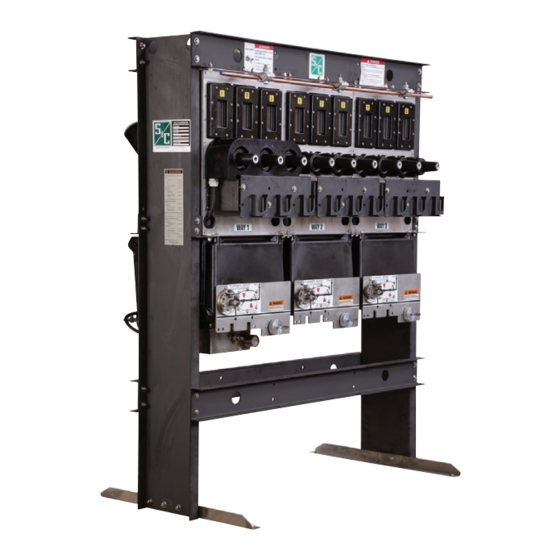
Page 6: Multi-Way Vault-Mounted Style
Safety Information Location of Safety Labels and Tags—Multi-Way Vault-Mounted Style Note: Manual operating handle is stored on mounting stand (not visible). Note: The installation and operation information kit is taped to the switchgear assembly. Designate a location where you can easily retrieve it and refer to it. Reorder Information for Safety Labels Location Safety Alert Message... -
Page 7: Pad-Mounted Style
Safety Information Location of Safety Labels and Tags—Pad-Mounted Style WARNING KEEP OUT Padlock Hazardous voltage inside. Can shock, burn, or cause death. If open or unlocked, immediately call electric company. G-6398 Note: The installation and operation information kit is stored in a slot behind the manual operation handle to the left of Way 1. -
Page 8: Safety Precautions
Safety Precautions DANGER Vista SD Underground Distribution Switchgear operates at high voltage. Failure to observe the precautions below will result in serious personal injury or death. Some of these precautions may differ from your company’s operating procedures and rules. Where a discrepancy exists, follow your company’s operating procedures and rules. -
Page 9: Shipping And Handling
Shipping and Handling Packing Vault-mounted style Vista SD Underground Distribution Switchgear is shipped in a wooden crate. Pad-mounted style Vista SD Underground Distribution Switchgear is fastened to a wood skid. At the first opportunity, remove all packing materials (cardboard, paper, foam padding, etc.) from the switchgear assembly. -
Page 10: Handling
Shipping and Handling Handling WARNING Vertical orientation (catalog number suffix “-V1” When handling Vista SD Underground Distribution or “-V2”) Switchgear with an overhead hoist, observe standard lifting practices as well as the general instructions below. Failure to follow these precautions can result in serious personal injury or equipment damage. - Page 11 Shipping and Handling Figure 5. Hoisting a multi-way vault-mounted style Vista SD switchgear assembly. Figure 6. Hoisting a pad-mounted style Vista SD switchgear assembly (multi-way assembly shown). S&C Instruction Sheet 695-505...
-
Page 12: Vault-Mounted Style Switchgear Placement
Installation Vault-Mounted Style Switchgear Placement STEP 1. At the installation site, remove all separately packaged components (if any) shipped with the switchgear assembly and set them aside. STEP 2. Remove switchgear assembly from its crate and lift it into place, observing the precautions given under the “Handling”... -
Page 13: Single-Way Vault-Mounted Style Unit Installed Through 31½-Inch Manhole
Installation Single-Way Vault-Mounted Style Unit Installed Through 31½-Inch Manhole STEP 1. At the installation site, remove all separately packaged components (if any) shipped with the switchgear assembly and set them aside. STEP 2. Remove switchgear assembly from its crate. Bushing or bushing Bushing or bushing Bushing or bushing well adapters... -
Page 14: Cables
Installation Cables WARNING Before energizing the switchgear, replace the shipping covers on all bushings and bushing wells with elbows or insulated protective covers or caps. Failure to replace the shipping covers on all bushings with elbows or insulated protective covers or caps can result in a flashover and serious personal injury or death. -
Page 15: Grounding
Installation Grounding STEP 1. Connect the ground pads on each way of the switchgear assembly to the system ground in accordance with the user’s standard grounding practice. See Figure 9 on page 14. STEP 2. If the switchgear is furnished with the continuous ground bus (catalog number suffix “-O”), connect the ground bus to the system ground in accordance with the user’s standard... -
Page 16: Pad-Mounted Style Switchgear Placement
Installation Pad-Mounted Style Switchgear Placement At the installation site, remove all separately STEP 1. Shipping packaged components (if any) shipped within clamp the pad-mounted gear enclosure and set them aside. STEP 2. Unbolt the switchgear assembly from its skid and lift the unit onto the mounting pad, observing the precautions given under the “Handling”... - Page 17 Installation STEP 3. Lift the hinged roof to approximately 45° above horizontal; the “hold-open” latching mechanism will engage automatically. See Figure 13. WARNING After lifting the roof open and ensuring the “hold-open” latching mechanism is engaged, release pressure on the hinged roof slowly.
-
Page 18: Cables
Installation Cables STEP 1. Remove the cover panels by unscrewing the pins connecting the panels to the front of the enclosure. Lift the front of each panel upwards and pull outwards to disengage the tab at the back of the panel from the slot at the bottom of the operating mechanism. - Page 19 Installation NOTICE ALWAYS follow proper cable-installation practices. When installing cable that will be attached to the switchgear, provide a strain- relief segment to minimize the load on the bushings. Cables must be allowed to expand and flex without putting a significant load on the bushings.
-
Page 20: Attach Hinged-Roof Counterweights
Installation Attach Hinged-Roof Counterweights STEP 1. If the roof was previously lifted to the second most vertical position, return it to the 45° position. On the right-hand side of the switchgear enclosure, while pushing up on the hinged roof, release the latch on the “hold-open” mechanism. See Figure 23 on page 23. -
Page 21: Install Termination Compartment
Installation Install Termination Compartment Cover Panels Carefully re-install the cover panels over each way by inserting the tab at the back of the panel into the slot at the bottom of the operating mechanism. See Figure 19. When lowered to the horizontal position, tighten the pins on the front of the panel to engage them with the front of the enclosure. -
Page 22: Fault Indicators
Installation Fault Indicators Fault indicators are to be furnished by the user and installed in accordance with the manufacturer’s instruc- tions. Optional mounting provisions for fault indicators (catalog number suffix “-F1” or “-F2”) are available for Vista SD Underground Distribution Switchgear. If mounting provisions are specified, mount the fault indicators on the mounting brackets and attach the associated sensors to the cables below the cable terminations. -
Page 23: Closing The Doors And The Hinged Roof
Installation Closing the Doors and the Hinged Roof STEP 1. Lift door-holder mechanism up to allow left- hand door to swing closed. See Figure 22. Make sure the fi nger latch engages the pin. See Figure 15 on page 17. STEP 2. -
Page 24: Completing The Installation
Installation Completing the Installation STEP 1. A resilient closed-cell gasket on the bottom fl ange of the enclosure protects the fi nish from being scratched during installation and isolates it from the alkalinity of a concrete foundation. This gasket also helps to seal the enclosure; to guard against entry of rodents, insects, and Bottom of weeds;... -
Page 25: Routine Switchgear Testing
Appendix A Routine Switchgear Testing Dc Cable Testing and Fault Locating For the convenience of users who normally perform Dc testing of installed cables is performed to determine electrical tests on system components such as switch- the condition of the cables and to locate faults. Industry gear, appropriate withstand test values for Vista SD standards such as IEEE 400, “IEEE Guide for Making Underground Distribution Switchgear are given in the... -
Page 26: Very Low Frequency (Vlf) Cable Testing
Appendix A Vista SD Underground Distribution Switchgear has An acceptance test is a field test made after installa- been designed to allow dc testing of the cables with the tion of the power cable system, including terminations other ways of the gear energized. After testing, the dc test and joints, but before the cable system is placed in normal equipment should be used to discharge any stored charge service. -
Page 27: Fault-Interrupter Testing
Appendix A NOTICE WARNING The VLF ac withstand capacity of the switchgear may When VLF cable testing has been completed, be reduced because of aging, damage, or electrical or or has been interrupted, the cable system and the mechanical wear. Therefore, the ac test voltage must test equipment must be discharged.
Need help?
Do you have a question about the Vista SD 101 and is the answer not in the manual?
Questions and answers