Quantifi Photonics 1000 Series User Manual
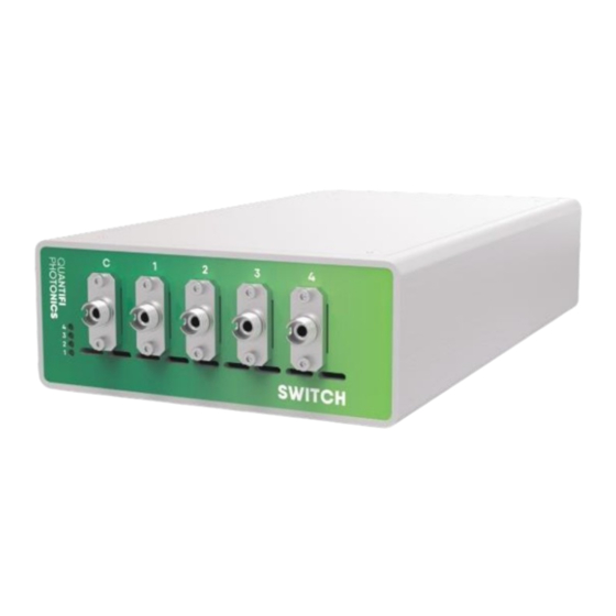
Automated optical switch
Hide thumbs
Also See for 1000 Series:
- User manual (61 pages) ,
- User manual (86 pages) ,
- User manual (57 pages)
Table of Contents
Advertisement
Quick Links
Advertisement
Table of Contents

Subscribe to Our Youtube Channel
Related Manuals for Quantifi Photonics 1000 Series


Summary of Contents for Quantifi Photonics 1000 Series
- Page 2 Information provided by Quantifi Photonics is believed to be accurate and reliable. However, no responsibility is assumed by Quantifi Photonics for its use nor for any infringements of patents or other rights of third parties that may result from its use. No license is granted by implication or otherwise under any patent rights of Quantifi Photonics.
-
Page 3: Table Of Contents
Cohesion Installer information for PXIe modules ..................... 16 6.1.1 Installation overview ............................. 16 6.1.2 Installation process ............................16 Quantifi Photonics PXIe system utility applications ..................18 6.2.1 Cohesion Manager utility ..........................19 6.2.2 Cohesion Firmware Updater utility ....................... 20 Quantifi Photonics Ltd. - Page 4 SCPI Multi Chassis commands ....................... 45 SCPI Command Console (available on MATRIQ instruments) ..............47 10 Example: Control of a Switch 1000/1100/1400 Series with SCPI ...... 49 NI-MAX application ................................ 49 NI-VISA application ................................ 50 Python® 2.7 code example............................51 Quantifi Photonics Ltd. Version 3.04...
- Page 5 12 Technical support ......................56 Contacting the Technical Support Group ......................56 Transportation ................................. 56 13 Warranty ..........................57 General information ............................... 57 Liability ....................................57 Exclusions .................................... 57 Certification ..................................58 Service and repairs ............................... 58 Quantifi Photonics Ltd. Version 3.04...
-
Page 6: Conventions
Refers to information about this product that you should not overlook. Indicates some information that requires your attention or some extra information for the current topic. Quantifi Photonics Ltd. Version 3.04... -
Page 7: Safety Information
• Wherever the symbol is printed on the unit, refer to the instructions provided in the device documentation for related safety information Ensure that the required conditions are met and understood before using the product. Quantifi Photonics Ltd. Version 3.04... -
Page 8: Introducing The Switch 1000/1100/1400 Series - Optical Switch
Channel 2 routing optical ports Channel 3 common optical port Channel 3 routing optical ports Channel 4 common optical port Channel 4 routing optical ports PXIe module / optical connector information Fastening clip Switch PXIe module information PXIe headers Quantifi Photonics Ltd. Version 3.04... -
Page 9: Crossover Switch Pxie Module
Switch PXIe module information 3.1.4 1xN Switch PXIe modules (1106 example) Fastening screws Error status LED Common optical port Routing optical ports PXIe module / optical connector information Fastening clip Switch PXIe module information PXIe headers Quantifi Photonics Ltd. Version 3.04... -
Page 10: Switch 1000/1100/1400 Matriq Instruments Overview
Switch 1000/1100/1400 MATRIQ instruments overview • You must use the external power supply that has been supplied by Quantifi Photonics with the unit. Any attempt to use a different external power supply may cause product damage and will void your warranty. -
Page 11: Status Leds
3.3.5 1xN Switch • Blinking yellow - Indicates initialization on startup. • Solid green - Indicates successful initialization and communication. • Solid red - Indicates a Switch error. Most likely an initialization error at startup. Quantifi Photonics Ltd. Version 3.04... -
Page 12: Connecting Optical Fibers
To ensure maximum power and to avoid erroneous readings always inspect fiber end faces. Make sure they are cleaned as detailed below before inserting into any port. Quantifi Photonics is not responsible for damage or errors caused by bad fiber cleaning or handling. -
Page 13: Handling The Switch 1000/1100/1400 Series Products
After powering on the PXIe chassis, please wait at least 2 minutes before attempting to communicate with the instrument. This will allow the chassis enough time to finish boot procedures and initialize the communication server. Quantifi Photonics Ltd. Version 3.04... -
Page 14: Switch 1000/1100/1400 Pxie Module Uninstallation
STEP 3: Pull out the module. chassis screws and fastening clip USE THE FASTENING CLIP TO PULL. DO NOT PULL ON THE CONNECTORS STEP 4: Store module in STEP 5: Power ON the chassis antistatic bag Quantifi Photonics Ltd. Version 3.04... -
Page 15: Switch 1000/1100/1400 Matriq Instrument Installation
USB via Ethernet • You must use the external power supply that has been supplied by Quantifi Photonics with the unit. Any attempt to use a different external power supply may cause product damage and will void your warranty. -
Page 16: Software Installation Information For Switch 1000/1100/1400 Series
Minimum System Requirements: 64bit OS, Windows 7 or above. Recommended System Requirements: 64bit Windows 10. The Cohesion Installer is a single installation package that contains all the required drivers and software, to support and control Quantifi Photonics modules on the PXIe Platform. 6.1.1 Installation overview For the PXIe Controller to communicate with the Switch 1000/1100/1400 Series installed in the chassis, software and driver installations are necessary. - Page 17 To operate in Multiple Chassis Mode, additional hardware modules are required. The Chassis Mode can be changed at any time, so it is recommended to select Single Mode until all other configuration requirements have been met. Quantifi Photonics Ltd. Version 3.04...
-
Page 18: Quantifi Photonics Pxie System Utility Applications
7. After rebooting the system, on startup a User Account Control prompt will be displayed to run the Cohesion Firmware Updater Utility. Click Yes and proceed with the application. Quantifi Photonics PXIe system utility applications Contained within the CohesionInstaller 3.XX.XX are two utility applications: •... -
Page 19: Cohesion Manager Utility
The Driver and SCPI services need to be running to facilitate communication with any installed Quantifi Photonics module, therefore they are listed as REQUIRED. On the right side of the Cohesion Manager window a list of all the installed Quantifi Photonics system utilities is displayed. -
Page 20: Cohesion Firmware Updater Utility
Whenever a new version of the CohesionInstaller is installed on the system, the Cohesion Firmware Updater utility will automatically launch after the system is rebooted. It will show the user the firmware status of all installed Quantifi Photonics modules and allow the user to update the firmware to a new version if applicable. -
Page 21: Installing Software For Matriq Instruments
Installing Cohesion Operator on client computer(s) Set up any computer you use to connect with the instrument by installing the latest Cohesion Operator software package. Cohesion Operator enables you to connect with Quantifi Photonics instruments on your network and manage firmware upgrades. - Page 22 From Cohesion Operator you can: Select a Quantifi Photonics instrument that is available on your network. Validate the IP address of the instrument and retrieve instrument information (refer 6.3.2). Communicate with the instrument through the SCPI Command Console (refer 0).
-
Page 23: Checking Matriq Firmware Versions And Other Product Information
You can check the details of a MATRIQ instrument, for example by doing one of the following: In the Cohesion Operator: Select the instrument. Click Connect. Current instrument information will be displayed. In CohesionUI: Select INFO on the menu. Instrument information will be displayed in the info panel. Quantifi Photonics Ltd. Version 3.04... -
Page 24: Upgrading A Matriq Instrument With The Latest Firmware
To confirm the new firmware version, click Connect to retrieve the latest instrument information. If an upgrade attempt is unsuccessful, the Cohesion Operator will stop the upgrade process and restore the MATRIQ instrument to its previous firmware version. Messages will be displayed accordingly. Quantifi Photonics Ltd. Version 3.04... -
Page 25: Restoring Factory Settings On A Matriq Instrument
Select the instrument by entering its IP address or by selecting it from the Discovery drop down list. (optional) Retrieve instrument information, including current firmware versions, by clicking Connect. Click Restore. IP address settings will also revert to factory settings. Quantifi Photonics Ltd. Version 3.04... -
Page 26: Cohesionui
Open Cohesion Operator on a client computer, for example by double-clicking the Cohesion Operator desktop icon. Select the instrument by entering its IP address or by selecting it from the Discovery drop down list. Click Open CohesionUI. Quantifi Photonics Ltd. Version 3.04... -
Page 27: Home Page
For PXIe modules, white numbers are displayed beside each module corresponding the slot in which they are installed. The EMPTY SLOTS button will toggle the page view to hide (HIDDEN), or to show (SHOWN) the empty slots in the PXIe chassis. The default setting is HIDDEN. Quantifi Photonics Ltd. Version 3.04... - Page 28 Automated Optical Switch | Switch 1000/1100/1400 Series For MATRIQ instruments, all the information relating to the instrument such as the model number, serial number and firmware versions are displayed in the top right corner of the window. Quantifi Photonics Ltd. Version 3.04...
-
Page 29: Modules List
Set and Actual values Some Quantifi Photonics products will allow the user to set a given parameter’s value and then read that parameter (eg. Laser, VOA, O2E, etc). In order to help the user to distinguish between a set value and an actual read value, CohesionUI will format these values differently according to the legend in the top right corner of the window. -
Page 30: Settings Page
• The unit preferences and settings can be set by hovering over the SETTINGS button in the left side menu. This will bring up a dropdown menu that lists all settings for a quick access. • Whenever the chassis is power cycled, CohesionUI reverts to default settings. Quantifi Photonics Ltd. Version 3.04... -
Page 31: System Controls For Pxie Modules
On the SETTINGS window there is a SYSTEM controls section. These controls are to facilitate re- discovery of any Quantifi Photonics PXIe modules there may have been installed after initial startup, or if no modules are displayed in the CohesionUI window. This is useful for users who are operating in a multi-chassis MXI setup, instead of the standard PXIe embedded controller setup. -
Page 32: Network And Update Settings Controls For Matriq Instruments
The MATRIQ instruments can operate over either an Ethernet or USB connection. To communicate with the instrument, the IP address is required. The Network interface controls are only available when connected over USB. When connected over Ethernet the settings will be locked, as highlighted as follows. Quantifi Photonics Ltd. Version 3.04... -
Page 33: Setting The Usb Ip Address For Matriq Instruments
IP address. This address can be found on the back of the instrument on the LCD screen. While connected over USB, typing in the assigned IP address in a supported web browser will open the CohesionUI page for the instrument. Quantifi Photonics Ltd. Version 3.04... -
Page 34: Scpi Command Console (Available On Pxie Modules)
ON, and once it has finished booting, check the IP address shown on the LCD screen. SCPI Command Console (available on PXIe modules) The CohesionUI SCPI Command Console enables you to communicate with Quantifi Photonics PXI modules via SCPI commands. It enables you to test commands and verify their syntax. - Page 35 For details on error codes, please refer to 9. *CLS Clear the response buffer and start fresh – useful when getting out of sync with WRITE and READ actions Quantifi Photonics Ltd. Version 3.04...
- Page 36 Click *ESR? to query the event status register and request information about the command failure. The instrument returns the error code, for example 32. For details on error codes, please refer to the *ESR? command. Quantifi Photonics Ltd. Version 3.04...
-
Page 37: Info Panel
Clicking the INFO button will display an information panel on the right side of the page. Information such as the chassis operation mode, manufacturer, model, and serial number of the chassis, CohesionUI version number, and the version of CohesionSCPI service running on the chassis is displayed in this panel. Quantifi Photonics Ltd. Version 3.04... -
Page 38: Switch 1000/1100/1400 Series Control With Cohesionui
After clicking the desired Switch module, its control page is displayed. All information relating to the module such as model number, serial number and firmware versions are displayed in the top right corner of the window. Quantifi Photonics Ltd. Version 3.04... - Page 39 The Switch can route the light very quickly, however there is a slight delay between re-routing the Switch and the UI updating the window. A grey circle will be displayed beside the current routed port. Quantifi Photonics Ltd. Version 3.04...
-
Page 40: Programming Guide
On PXIe modules you can use the SCPI Command Console in CohesionUI (refer 7.6 SCPI Command Console (available on PXIe modules)). On MATRIQ instruments you can use the SCPI Command Console that you can access from the Cohesion Operator (refer 0 Quantifi Photonics Ltd. Version 3.04... -
Page 41: Programming Conventions
In NI-MAX a RIO interface will show up, however there are no communication methods available or implemented on this interface. Quantifi Photonics products are ONLY accessible through the VISA TCPIP INSTR interface provided by the CohesionSCPI service installed on the system. -
Page 42: Common System Command Summary
*IDN? Description Query the chassis identification Parameters No parameters Comma separated string with the <manufacturer>,<server name>,<chassis Response controller name>,<server version> Example *IDN? -> Quantifi Photonics, CohesionSCPI service,PXIE-8133,FW2.0.15 Command *OPC? Syntax *OPC? Description Query the Operation Complete Status Parameters No parameters... -
Page 43: Specific Command Summary
Example :SLOT3:OPT? -> 1,, Command :SLOT<n>:IDN? Syntax :SLOT<n>:IDN? Query the Identifier for the slot; returns the manufacturer, part number, serial number, Description hardware and firmware versions Quantifi Photonics Ltd. Version 3.04... -
Page 44: Configuration Commands
Automated Optical Switch | Switch 1000/1100/1400 Series Parameters No parameters Comma separated string containing the <manufacturer>, <part number>, <serial Response number>,<hardware version><firmware version> :SLOT1:IDN? -> Quantifi Photonics,SwitchPXIe-1401-4- FC,QuantifiPhotonics-180101,HW1.0FW1.02 Example Hardware and firmware versions are not separated by a comma 9.5.2 Configuration commands Command :ROUTe<n>:ERROR? -
Page 45: Switch Pxie Multi Chassis Mode Operation
SINGLE mode, this will always return 1 In Single chassis mode: :SYSTEM:CHASSIS? -> 1 :SYSTEM:CHASSIS? LIST -> 0 :SYSTEM:CHASSIS? MODE -> SINGLE Example In Multi chassis mode: :SYSTEM:CHASSIS? -> 2 :SYSTEM:CHASSIS? LIST -> 2,3 :SYSTEM:CHASSIS? MODE -> MULTI Quantifi Photonics Ltd. Version 3.04... - Page 46 In Multi chassis mode, all the commands given above in the Specific Command Summary will still work, but they must be prefixed with :CHASSIS<c>. Common command example: Single Chassis Mode :SLOT2:IDN? Multi Chassis Mode :CHASSIS1:SLOT2:IDN? Specific command example: Single Chassis Mode :SOUR2:CHAN2:POW? MAX Multi Chassis Mode :CHASSIS1 SOUR2:CHAN2:POW? MAX Quantifi Photonics Ltd. Version 3.04...
-
Page 47: Scpi Command Console (Available On Matriq Instruments)
2. To switch to another Quantifi Photonics device: • Enter ip and press <ENTER>. • Enter the IP address of the Quantifi Photonics product you would like to switch to and press <ENTER>. • Confirm you are communicating with the right product: Enter *idn? and press <ENTER>. - Page 48 Automated Optical Switch | Switch 1000/1100/1400 Series 3. To send a command or query to a Quantifi Photonics device: • Enter a command and press <ENTER>. • The device will execute the command and return an action response to the console if applicable.
-
Page 49: 10 Example: Control Of A Switch 1000/1100/1400 Series With Scpi
Switch product via SCPI commands NI-MAX application To communicate with any Quantifi Photonics PXIe or MATRIQ product, the chassis / instrument must first be setup as a TCP/IP instrument. 1. After installing NI-MAX, launch the application. In the left side panel of the window, click the Devices and Interfaces option. -
Page 50: Ni-Visa Application
2. On the righthand side panel, select Open VISA Test Panel. A new window will popup. Click the Input / Output button from the window menu. Valid chassis and module commands can be entered in, and their returns queried. Quantifi Photonics Ltd. Version 3.04... -
Page 51: Python® 2.7 Code Example
"" print("writing a specific command") instrument.write(command) print("checking ESR") command "*ESR?" data = instrument.ask(command) print("*ESR?: " + data) except Vxi11Exception as e: # pass print("ERROR" + str(e) + ", command: " + str(command)) Quantifi Photonics Ltd. Version 3.04... -
Page 52: Matlab® Code Example
% Replace this with a valid command for your device (read the programming % guide section for examples) command = % Close the connection to the object. fclose(PXIE_Chassis); % Clean up all objects. delete(PXIE_Chassis); Quantifi Photonics Ltd. Version 3.04... -
Page 53: Labview™ Application
To control the Switch product with a LabVIEW™ Soft Panel, you will need to have setup the chassis / instrument as a TCP/IP Resource as shown in Section 10.1. Download the LabVIEW zip file from the Quantifi Photonics website. This contains all the Soft Panels and Virtual Instruments (VIs) for Quantifi Photonics PXIe modules. -
Page 54: Labview™ Virtual Instruments (Vis)
C:\Program Files\National Instruments\LabVIEW 20XX\instr.lib\ Within the Quantifi Photonics Ltd folder, navigate to the intended module’s sub folder. e.g. Quantifi Photonics Ltd > O2E > O2E > VXI This VI Tree can then be added into the desired development project, therefor the Soft Panel can be rebuilt and used by other LabVIEW Runtime Engine. -
Page 55: Maintenance
All Quantifi Photonics products are calibrated during manufacture, and each product is shipped to the customer with a Calibration Certificate. On this certificate, the calibration date, as well as the next calibration due date are mentioned. -
Page 56: 12 Technical Support
12 Technical support Contacting the Technical Support Group To obtain after-sales service or technical support for this product, contact Quantifi Photonics. The Technical Support Group is available to take your calls from Monday to Friday, 9:00 a.m. to 5:00 p.m. -
Page 57: 13 Warranty
For full warranty terms and conditions, please visit www.quantifiphotonics.com. Liability Quantifi Photonics shall not be liable for damages resulting from the use of the product, nor shall be responsible for any failure in the performance of other items to which the product is connected or the operation of any system of which the product may be a part. -
Page 58: Certification
Automated Optical Switch | Switch 1000/1100/1400 Series Certification Quantifi Photonics certifies that this equipment met its published specifications at the time of shipment from the factory. Service and repairs To send any equipment for service, repair or calibration please contact the Technical Support Group. - Page 59 3.04...
Need help?
Do you have a question about the 1000 Series and is the answer not in the manual?
Questions and answers