Table of Contents
Advertisement
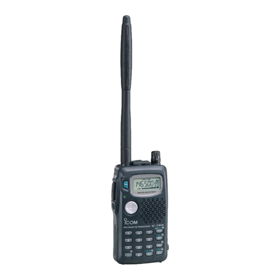
INSTRUCTION MANUAL
MULTIBAND FM TRANSCEIVER
iT81A/E
This device complies with Part 15 of the FCC rules. Operation is sub-
ject to the following two conditions: (1) This device may not cause
harmful interference, and (2) this device must accept any interference
received, including interference that may cause undesired operation.
Advertisement
Table of Contents

Subscribe to Our Youtube Channel
Related Manuals for Icom IC-T81A


Summary of Contents for Icom IC-T81A
- Page 1 INSTRUCTION MANUAL MULTIBAND FM TRANSCEIVER iT81A/E This device complies with Part 15 of the FCC rules. Operation is sub- ject to the following two conditions: (1) This device may not cause harmful interference, and (2) this device must accept any interference received, including interference that may cause undesired operation.
-
Page 2: Important
fire or electric shoc protection against such accidents and the transceiver will be ruined. Versions of the IC-T81A/E which display the “CE” symbol NEVER attempt to charge alkaline or dry cell batteries. Be- on the serial number seal, comply with the European har-... -
Page 3: Supplied Accessories
Otherwise, the battery pack or installed Ni-Cd batteries will become ex- hausted. For USA only: Caution: Changes or modifications to this transceiver, not ex- pressly approved by Icom Inc., could void your authority to operate this transceiver under FCC regulations. -
Page 4: Table Of Contents
TABLE OF CONTENTS I Memory editing ..................19 IMPORTANT ....................ii I Memory names ..................20 EXPLICIT DEFINITIONS ................ii CAUTIONS ..................... ii 7 DTMF MEMORY ..................21 SUPPLIED ACCESSORIES ................iii I Programming a DTMF code ..............21 TABLE OF CONTENTS ................. iv I Transmitting a DTMF code .............. -
Page 5: Accessory Attachment
ACCESSORY ATTACHMENT D Antenna D Handstrap D Belt clip Screw the supplied antenna onto the Attach the handstrap to the belt clip, be- Attach the belt clip to the transceiver as antenna connector as shown in the dia- fore attaching the belt clip to the trans- illustrated below. -
Page 6: Panel Description
PANEL DESCRIPTION I Switches, controls, keys and connectors u [SP/MIC] q MULTIFUNCTION SWITCH [MULTI] ➥ Push to select the tone or duplex menu. (pgs. 15–17); push for 1 sec. to enter set mode (p. 35). i [DIAL] ➥ Push ↕ to increase/decrease the volume (p. 11). ➥... - Page 7 PANEL DESCRIPTION !2 OUTPUT POWER KEY [H/L(LOCK)Î] This connection [SP] Remote Audio out (8 Ω) does not apply ➥ Push to toggle between low and high power. (p. 11) when a conden- • “LOW” appears while low power is selected. sor microphone 33 kΩ...
-
Page 8: I Function Display
PANEL DESCRIPTION I Function display T SQL SKIP VOL LOW... - Page 9 PANEL DESCRIPTION q FREQUENCY INDICATION o RIT/VXO INDICATOR (p. 13) Shows the selected frequency, set mode contents, etc. Appears when either the RIT or VXO function is activated and the 1.2 GHz band is selected. w MODE INDICATORS !0 LOW POWER INDICATOR (p. 11) Indicate the operating mode.
-
Page 10: Battery Packs And Charging
BATTERY PACKS AND CHARGING I Battery pack charging I About battery packs D Operating period The supplied* BP-198, BP-199 or BP-200 BATTERY PACK cludes rechargeable Ni-MH batteries and can be charged ap- Depending on attached battery pack, the operating period of prox. -
Page 11: I Charging Connections
BATTERY PACKS AND CHARGING I Charging connections Charging periods: 1 hour (w/BP-198 or BP-199) 1.5 hours (w/BP-200) D Regular charging Attach the sup- plied or optional Charging period: battery pack; 15 hours then, connect the supplied* wall charger via an AC outlet as shown at Wall charger right. -
Page 12: I Battery Case
BATTERY PACKS AND CHARGING I Battery case D Operation with an optional cable Connect an optional charger or cable to the transceiver as il- When using a battery case attached to the transceiver, install lustrated below. Be careful of battery overcharging as the 3 AA(R6) size alkaline batteries as illustrated below. -
Page 13: Basic Operation
BASIC OPERATION I Power ON I Setting a frequency D Via the keypad NOTE: Charge the battery pack before turning power on [Example] for the first time (pgs. 6–8) (from the MHz digits) ➀ Push [VFO] to select VFO Push and hold [PWR] for 1 sec. to turn power on. mode. -
Page 14: I Setting Tuning Steps
BASIC OPERATION I Setting tuning steps D Via the keypad [Example] SET MODE USING (from the decimal point) ➀ The transceiver has 9 tuning steps* (each band has indepen- Push [VFO] to select VFO dent settings) as follows: mode. ➁ 5 kHz 10 kHz 12.5 kHz... -
Page 15: I Selecting A Memory Channel
BASIC OPERATION I Selecting a memory channel I Receive and transmit ➀ ➀ Push [MR] to select mem- Push [PWR] for 1 sec. to turn power on. ➁ ory mode. Push [MULTI(↕)] to set a volume level. ➁ ➂ Push [MULTI(↔)] (or rotate Set the squelch level. -
Page 16: I Fm Broadcast Reception
BASIC OPERATION I FM broadcast reception play, then rotate [DIAL] to select a frequency; or, ➥ Select a frequency with the digit keys directly. • “AM” automatically appears when a frequency in the range The transceiver can receive FM radio broadcasts. These are 118–135.995 MHz is input. -
Page 17: I Rit/Vxoa Function
BASIC OPERATION I RIT/VXO function D Adjusting the frequency with RIT/VXO (1200 MHz band) Make sure that RIT or VXO is activated in set mode and that In the 1200 MHz band, differences between actual and dis- the 1200 MHz band is selected. ➀... -
Page 18: I Receive Mode
I Receive mode SET MODE USING The IC-T81A/E allows you to receive frequencies in the 50 MHz band in AM mode (as well as to transmit in FM narrow mode in the 144 MHz band for Italy, France and Europe ver- sions only—see p. -
Page 19: Repeater Operation
REPEATER OPERATION I General D Tone information Some repeaters require a tone to be accessed. In this case, precede step ➅ at left with the required tone. When using a repeater, the transmit frequency is shifted from the receive frequency by the offset frequency. It is convenient DTMF TONES to program repeater info into memory channels (pgs. -
Page 20: I Subaudible Tones For Repeater Use
REPEATER OPERATION I Subaudible tones I Setting an offset SET MODE SET MODE USING USING for repeater use frequency Some repeaters require subaudible tones to be accessed. When communicating through a repeater, the transmit fre- Subaudible tones are superimposed over your normal signal quency is shifted from the receive frequency by an amount and must be set in advance. -
Page 21: I Auto Repeater Function
REPEATER OPERATION I Auto repeater Frequency range and offset direction INITIAL SET MODE USING FREQUENCY RANGE DUPLEX DIRECTION function (USA version only) 145.200– 145.495 MHz “–DUP” appears The USA version automatically activates the repeater settings 146.610– 146.995 MHz (duplex, ON/OFF, duplex direction, tone encoder ON/OFF) 147.000–... -
Page 22: Memory/Call Programming
MEMORY/CALL PROGRAMMING I General I Programming a memory channel The transceiver has 124 memory channels (100 regular, 10 pairs of scan edge channels for mixed bands and 1 call chan- ➀ Push [VFO] to select VFO mode. nel for each band—VHF, UHF, 50 MHz and 1200 MHz). Note ➁... -
Page 23: I Memory Editing
MEMORY/CALL PROGRAMMING I Memory editing D Clearing a memory Memories can be cleared from VFO or memory mode. ➀ Memory (call) channel contents can be moved to VFO or to Push [ MW] for 1 sec. to enter (MR) another memory. memory menu mode. -
Page 24: I Memory Names
MEMORY/CALL PROGRAMMING I Memory names mode. • Push [ MW] for 1 sec. to erase a channel’s name and return (MR) to VFO mode. Memory channels can be programmed with names of up to • When in memory mode push [MR] to toggle between memory six characters. -
Page 25: Dtmf Memory
DTMF MEMORY I Programming a DTMF code I Transmitting a DTMF code D Using a DTMF memory channel The transceiver has 9 DTMF memory channels (D1 to D9) for ➀ storage of often-used DTMF codes of up to 16 characters. Push [ MW] for 1 sec. -
Page 26: Scan Functions
SCAN FUNCTIONS I Scan types FULL SCAN PROGRAMMED SCAN (p. 23) Repeatedly scans all fre- (p. 23) Repeatedly scans be- quencies over a selected tween two user-pro- band. grammed frequencies. Band Scan edges Band Band Band edge edge edge edge Used for checking for fre- quencies within a speci- Scan... -
Page 27: I Full/Programmed Scan
SCAN FUNCTIONS I Full/programmed scan I Memory (skip) scan ➀ ➀ Push [VFO] to select VFO mode, if necessary. Push [MR] to select memory mode, if necessary. ➁ ➁ Push [MULTI(↔)] for 1 sec. to start the scan; after that, Push [MULTI(↔)] for 1 sec. -
Page 28: I Skip Channel Setting
SCAN FUNCTIONS I Skip channel setting I Scan resume SET MODE USING condition Memory channels can be set to be skipped during memory scan. This is useful to speedup the memory scan interval. The resume condition can be selected as a pause or timer ➀... -
Page 29: Subaudible Tone Operation
SUBAUDIBLE TONE OPERATION I Tone squelch D Setting subaudible tones for SET MODE USING tone squelch operation (CTCSS* tones) The tone squelch opens only when receiving a signal con- Separate tone frequencies can be set for tone squelch oper- taining a matching subaudible tone. You can silently wait for ation than for repeater operation (the same range of tones is calls from group members using the same tone. -
Page 30: I Tone Scan
SUBAUDIBLE TONE OPERATION I Tone scan I Pocket beep operation The transceiver can detect the subaudible tone frequency in a This function uses subaudible tones for calling and can be received signal. By monitoring a signal, such as that being used as a “common pager”... -
Page 31: Other Functions
OTHER FUNCTIONS I Help function NOTE: VFO mode cannot be se- lected via the microphone when SIMPLE mode is selected. When in set mode or initial set mode and no operation is per- formed for 5 sec., the name of the selected item scrolls across the function display for convenience. -
Page 32: Display Backlighting
OTHER FUNCTIONS D Auto power OFF D Beep tones ON/OFF This item allows you to set a time at Confirmation beep tones normally which the transceiver will automati- sound when you push a key or switch. cally turn off. The power off time can These can be turned ON (default) or be set to 20, 40, 60 min. -
Page 33: I Resetting The Cpu
OTHER FUNCTIONS I Resetting the CPU D Voltage display POWER ON This item sets the voltage display ON (default) or OFF. When set to ON, Reset the CPU before operating the transceiver for the first battery voltage is briefly displayed time, or when the internal CPU malfunctions. -
Page 34: I Cloning
OTHER FUNCTIONS I Cloning ceiver. POWER ON • When cloning is finished, “CLONE” appears in the master trans- ceiver’s display and “CL END” appears in the slave transceiver’s Cloning allows you to quickly and easily transfer the pro- display. grammed contents from one transceiver to another trans- ➃... -
Page 35: Troubleshooting
TROUBLESHOOTING If your transceiver seems to be malfunctioning, please check the following points before sending it to a service center. PROBLEM POSSIBLE CAUSE SOLUTION REF. No power comes on. • The battery is exhausted. • Charge the battery pack or place new dry cell bat- pgs. -
Page 36: Specifications
SPECIFICATIONS GENERAL TRANSMITTER • Frequency coverage (Unit: MHz) • Modulation system : Variable reactance modulation • Output power (at 13.5 V DC) : High 5 W typ. (except 1200 MHz) Version 50 MHz 144 MHz 430 MHz 1.2 GHz 1 W (1200 MHz) Rx: 118–173.995 Rx: 400–469.995 50–54... -
Page 37: Options
OPTIONS D Battery packs D Speaker-microphones BATTERY VOLTAGE OUTPUT OPERATING HM-46 HM-54 CAPACITY PACK POWER PERIOD* Battery case for R6(AA) BP-197 0.8 W 10/14 hr × 3 alkaline or Ni-Cd cells BP-198 700 mAh 1.2 W 6/8.5 hr 4.8 V BP-199 700 mAh 2.0 W... -
Page 38: Mode Arrangement
MODE ARRANGEMENT VFO MODE *NOTE: push for 1 sec. Additional bands may be available here depending on version. MEMORY MENU push for 1 sec. CALL Memory clear (p. 19) CLR MHz Skip setting (p. 24) Memory names (p. 20) MEMORY MODE Memory write condition... - Page 39 MODE ARRANGEMENT SET MODE Repeater tones (p. 15) Receive mode* (p. 14) Tuning step* (p. 10) CLR MHz CTCSS tones (p. 25) Offset frequency* (p. 16) RIT/VXO* (p. 13) Scan resume (p. 24) T SQL Cannot be selected when entering set mode from a memory or call channel; * 50 MHz band only;...
-
Page 40: I Getting Started
Count on us! A-5571D-1EX Printed in Japan 6-9-16 Kamihigashi, Hirano-ku, Osaka 547-0002 Japan © 1999 Icom Inc.
Need help?
Do you have a question about the IC-T81A and is the answer not in the manual?
Questions and answers