Table of Contents
Advertisement
Quick Links
Advertisement
Table of Contents

Related Manuals for Icom IC-T7H


Summary of Contents for Icom IC-T7H
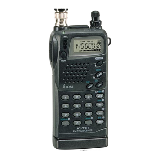
- Page 1 SERVICE MANUAL DUAL BAND FM TRANSCEIVIER...
- Page 2 INTRODUCTION This service manual describes the latest service information for the IC-T7H DUAL BAND FM TRANSCEIVER at the time of publication. 4 version of the IC-T7H have been designed. This serves manual cover each versions. MODEL VERSION SYMBOL Europe Italy...
-
Page 3: Table Of Contents
TABLE OF CONTENTS SECTION SPECIFICATIONS SECTION INSIDE VIEWS SECTION DISASSEMBLY INSTRUCTIONS SECTION CIRCUIT DESCRIPTION 4 - 1 RECEIVER CIRCUITS ........... . .4 - 1 4 - 2 TRANSMITTER CIRCUITS . - Page 4 SECTION 1 SPECIFICATIONS 144 MHz band 430 MHz band Tx: 144 MHz–148 MHz Tx: 430 MHz–450 MHz* USA-3 Rx: 118 MHz–174 MHz* Rx: 400 MHz–470 MHz* Europe 144 MHz–146 MHz 430 MHz–440 MHz Frequency Tx: 140 MHz–148 MHz* SE Asia 430 MHz–440 MHz coverage Rx: 118 MHz–174 MHz*...
- Page 5 SECTION 2 INSIDE VIEWS • LOGIC UNIT AND 2F UNIT 2F UNIT LOGIC UNIT UHF band pass filter (FI201: EFCH445MWN) UHF RF amplifier* CPU system clock (Q201: 2SC4226) (X1: CR534 5.03MHz) AF power amplifier (IC151: 2SC5226) CPU system clock (IC1: M38267M8L-165GP) VHF RF amplifier* (Q51: 2SC5226) Speaker...
-
Page 6: Section 3 Disassembly Instructions
SECTION 3 DISASSEMBLY INSTRUCTIONS • • DISASSEMBLING PANELS REMOVING 2F UNIT 1 Unscrew 4 screws, A from the rear panel and 2 screws, B 1 Unscrew 1 screw, E from the 2F unit. 2 Unsolder the point, F, then remove the 2F unit with the from the rear plate to separate front and rear panels. -
Page 7: Section 4 Circuit Description
SECTION 4 CIRCUIT DESCRIPTION RECEIVER CIRCUITS 4-1-4 UHF RF CIRCUIT (2F UNIT) The signals from the antenna switching circuit (1F unit; 4-1-1 DUPLEXER CIRCUIT (1F UNIT) D551, D552, D722–D724 and Q204) are applied to the limit- The transceiver has a duplexer (low-pass and high-pass fil- ter (D201), and are then amplified at the the RF amplifier ters) on the first stage from the antenna connector to sepa- (Q201). -
Page 8: Transmitter Circuits
The 1st IF signal (45.15 MHz) from the IF amplifier (Q101) TRANSMITTER CIRCUITS is applied to the 2nd mixer section of IC101 (pin 16), and is 4-2-1 MICROPHONE AMPLIFIER CIRCUIT mixed with the 2nd LO signal (45.6 MHZ) for conversion to (LOGIC AND 2F UNIT) a 450 kHz 2nd IF signal at the 2nd mixer section. -
Page 9: Pll Circuits
4-2-4 APC CIRCUIT (1F AND 2F UNITS) PLL CIRCUITS The APC circuit stabilizes transmit output power and selects 4-3-1 VHF PLL CIRCUIT (1F UNIT) HIGH and LOW output power. The APC circuit consists of The oscillated signal at the VCO circuit (DUAL VCO board; APC sensor, APC control (1F unit) and APC set (2F unit) cir- Q304, Q305 and D303) is amplified at a buffer-amplifier cuits. -
Page 10: Power Supply Circuits
4-4 POWER SUPPLY CIRCUITS OTHER CIRCUITS VOLTAGE LINE 4-5-1 TONE SQUELCH CIRCUIT (LOGIC UNIT) DESCRIPTION A portion of the detected audio signals from the “DETO” line LINE are passed through the low-pass filter (IC13). The filtered The voltage from the external power supply or signal is then applied to the CPU (IC1, pin 4), and is com- attached battery pack. -
Page 11: Port Allocations
4-5 PORT ALLOCATIONS 4-5-1 CPU (LOGIC UNIT; IC1) Port Port Description Description number name number name Input port for remote control signal Outputs LCD backlight control signals. LIGHT REMOTE from an optional HM-75A microphone “High” : The backlight lights. via the [EXT MIC] jack. Output port for the microphone ampli- Input port for detected S-meter signals MICC... -
Page 12: Section 5 Adjustment Procedures
SECTION 5 ADJUSTMENT PROCEDURES 5-1 PLL AND TRANSMITTER ADJUSTMENT ADJUSTMENT MEASUREMENT POINT ADJUSTMENT ADJUSTMENT CONDITION VALUE UNIT LOCATION UNIT ADJUST PLL LOCK • Displayed frequency : Connect a digital 1.3 V DUAL- L303 VOLTAGE 145.000 MHz multimeter or an (VHF) •... - Page 13 • 1F UNIT FREQUENCY COUNTER 100 MHz–500 MHz C369 L301 PLL frequency adjustment PLL lock voltage (Adjustable via openings adjustment for UHF on the 2F unit) VLV* ULV* PLL lock voltage check PLL lock voltage check point for VHF point for UHF L303 PLL lock voltage adjustment for VHF...
-
Page 14: Receiver Adjustment
5-2 RECEIVER ADJUSTMENT ADJUSTMENT MEASUREMENT POINT ADJUSTMENT ADJUSTMENT CONDITION VALUE UNIT LOCATION UNIT ADJUST • Displayed frequency : Connect a digital Maximum DC voltage Adjust in 145.000 MHz [EUR] multimeter or oscil- sequence SENSITIVITY 146.000 MHz [Other] loscope L53, check point “S”. L54, •... - Page 15 • 2F UNIT Terminator for the S-meter adjustment 68 k speaker STANDARD SIGNAL GENERATOR (SSG) 100–500 MHz –127 to – 17 dBm (0.1 V to 32 mV) CAUTION: DO NOT transmit while the signal generator is connected. VHF sensitivity L102 adjustment UHF sensitivity adjustment...
-
Page 16: Section 6 Parts List
SECTION 6 PARTS LIST [1F UNIT] [1F UNIT] ORDER ORDER DESCRIPTION DESCRIPTION IC250 1110002700 S.IC NJM2904M-T1 L352 6200003550 S.COIL MLF1608A 4R7K-T IC851 1130007610 S.IC µPD3140GS-E1 (DS8) L353 6200003550 S.COIL MLF1608A 4R7K-T L354 6200004480 S.COIL MLF1608D R82K-T L355 6200004480 S.COIL MLF1608D R82K-T Q201 1530000371 S.TRANSISTOR 2SC3356 R25-T2B... - Page 17 [1F UNIT] [1F UNIT] ORDER ORDER DESCRIPTION DESCRIPTION ERJ2GEJ 101 X (100 Ω) R708 7030004980 S.RESISTOR C360 4030011600 S.CERAMIC C1608 JB 1C 104KT-N R709 7030005040 S.RESISTOR ERJ2GEJ 472 X (4.7 kΩ) C361 4030009810 S.CERAMIC C1005 JB 1E 102K-T-A ERJ2GEJ 470 X (47 Ω) R710 7030004970 S.RESISTOR C362...
- Page 18 [1F UNIT] [DUAL-VCO BOARD] ORDER ORDER DESCRIPTION DESCRIPTION ERJ2GEJ 101 X (100 Ω) 7120000470 JUMPER ERDS2T0 R313 7030004980 S.RESISTOR 7030003860 S.JUMPER ERJ3GE JPW V R314 7030005290 S.RESISTOR ERJ2GEJ 682 X (6.8 kΩ) ERJ2GEJ 221 X (220 Ω) 7030000010 S.JUMPER MCR10EZHJ JPW (000) R315 7030004990 S.RESISTOR ERJ2GEJ 470 X (47 Ω)
- Page 19 [2F UNIT] [2F UNIT] ORDER ORDER DESCRIPTION DESCRIPTION Q602 1590002380 S.TRANSISTOR XP1115 (TX) R107 7030005220 S.RESISTOR ERJ2GEJ 223 X (22 kΩ) Q901 1520000460 S.TRANSISTOR 2SB1132 T100 R R108 7030007340 S.RESISTOR ERJ2GEJ 153 X (15 kΩ) Q902 1590002580 S.FET HAT1024R-EL R110 7030005220 S.RESISTOR ERJ2GEJ 223 X (22 kΩ) R111...
-
Page 20: Logic Unit
[2F UNIT] [2F UNIT] ORDER ORDER DESCRIPTION DESCRIPTION 4550002890 S.TANTALUM TESVA 1A 225M1-8L C416 4030009810 S.CERAMIC C1005 JB 1E 102K-T-A 4030009810 S.CERAMIC C1005 JB 1E 102K-T-A C501 4030011320 S.CERAMIC C1005 CH 1E 470J-T-A 4030009740 S.CERAMIC C1005 CH 1E 100D-T-A C601 4030006860 S.CERAMIC C1608 JB 1H 102K-T-A 4030009810 S.CERAMIC... - Page 21 [LOGIC UNIT] [LOGIC UNIT] ORDER ORDER DESCRIPTION DESCRIPTION 1590001860 S.TRANSISTOR UN9215 (TX) R216 7030003800 S.RESISTOR ERJ3GEYJ 105 V (1 MΩ) 1590001690 S.TRANSISTOR UN9115 (TX) R218 7030003680 S.RESISTOR ERJ3GEYJ 104 V (100 kΩ) R219 7030003840 S.RESISTOR ERJ3GEYJ 225 V (2.2 MΩ) R220 7030003560 S.RESISTOR ERJ3GEYJ 103 V (10 kΩ)
- Page 22 [LOGIC UNIT] ORDER DESCRIPTION C172 4030011600 S.CERAMIC C1608 JB 1C 104KT-N C173 4030006870 S.CERAMIC C1608 JB 1H 222K-T-A C174 4030009820 S.CERAMIC C1005 JB 1C 103K-T-A C175 4030011600 S.CERAMIC C1608 JB 1C 104KT-N C178 4030011600 S.CERAMIC C1608 JB 1C 104KT-N C179 4030007130 S.CERAMIC C1608 CH 1H 101J-T-A C180...
- Page 23 SECTION 7 MECHANICAL PARTS AND DISASSEMBLY [LOGIC UNIT] [CHASSIS PARTS] REF. NO. ODER NO. DESCRIPTION QTY. REF. NO. ODER NO. DESCRIPTION QTY. 8900005320 Flat cable OPC-519 6510018560 Antenna connector BNC-R128 (incl. nut) 5030001230 LCD LD-BU4323J 8210013462 1600 rear panel (A)-2 8310034261 1460 contact base-1 8930037201 LCD contact SRCN-1600 ZNN-1 8010017660 2207 chassis...
- Page 24 MP8 (C) MP16 (L) MP9 (C) J1 (C) LOGIC UNIT MP10 (L) MP21 (C) MP13 (C) MP33 (C) MP1 (L) MP19 (C) MP1 (C) EP2 (L) W1 (L) MP13 (C) DS4 (L) MP24 (C) J1 (C) MP5 (L) MP1 (1F) MP3 (L) MP13 (C) MP2 (1F)
- Page 25 SECTION 8 SEMI-CONDUCTOR INFORMATION • • DIODES TRANSISTOR AND FET’S 2SA1588 GR 2SB1132 R 2SB1201 S 2SB1462 R 2SC3356 R25 1SV271 DA112 DA113 DAP202U MA8051H (Symbol: TG) (Symbol: ZG) (Symbol: BARB) (Symbol: B1201) (Symbol: BR) (Symbol: R25) (Symbol: AZ) (Symbol: AY) (Symbol: P) (Symbol: 5^1) 2SC4081 S...
- Page 26 SECTION 9 BOARD LAYOUTS 9 - 1 LOGIC UNIT • TOP VIEW 9 - 1...
- Page 27 • BOTTOM VIEW FROM 2F UNIT J2 C200 B4790A C208 R216 R184 R211 R215 C171 R240 R197 R209 R210 R141 R230 R143 C130 C175 R190 C206 C157 R207 R146 C133 R142 C132 R223 C173 R236 R145 R218 C141 C148 R156 R238 C147 C140...
-
Page 28: Unit
9 - 2 2F UNIT • 2F UNIT (TOP VIEW) Q151 C152 C156 IC151 FI201 Q152 EXTMIC C160 INTSP R314 R308 AFON R158 PLST C917 PLCK C918 PDA/UL REMOTE DICK DIUD C919 IC301 C414 C415 LVCO HVCO C300 C922 SHIFT R502 TXSEL L102... - Page 29 • 2F UNIT (BOTTOM VIEW) C608 C606 D603 C609 C605 Q602 D607 L607 L606 D605 C611 C610 C151 C620 L202 R602 R203 C617 D606 L204 D601 D602 C800 L201 R201 C206 R202 EXTMIC R401 R403 C404 R404 INTSP UMOD R207 REMOTE NMOD TXSEL...
-
Page 30: Unit
9 - 3 1F UNIT • 1F UNIT (TOP VIEW) C733 R731 C736 C732 L725 J902 C907 C553 X851 D552 EXTMIC UOUT J202 UMOD INTSP C369 J905 VMOD REMOTE J905 PLST TXSEL VOUT PLCK DIUD C101 PDA/UL DICK R370 2NDLO PSET C376 VCC2... - Page 31 • 1F UNIT (BOTTOM VIEW) R902 R709 C903 D702 R261 C713 C254 Q704 R701 R702 Q202 Q705 C911 C552 D722 D703 R727 UOUT R728 L551 IC250 D723 C730 R365 D724 C368 Q204 VOUT C367 C727 C725 C366 IC851 R265 C232 R724 VCC2 C901...
-
Page 32: Block Diagram
SECTION 10 BLOCK DIAGRAM SHIFT Q702: 2SB1132 Q703: 2SD2216 Q705: 2SA1588 DUAL VCO BOARD D702: MA133 Q203: UN9210 D703: MA2S111 Q353: TXSEL UN9115 BAND CTRL LVCO LVCO CTRL Q304: 2SC5108 D51: MA2S077 Q354: UN9210 PA BOARD Q305: 2SC5108 D52: MA2S077 Q357: D303: MA304 D202: MA2S077... - Page 33 SECTION 11 VOLTAGE DIAGRAM • LOGIC UNIT CS028014-12 C167 C166 DS4 LD-BU4323J 0.001 0.001 CLONEIN 0.2 ns D1 MA2S111 2.0 v 15 k C215 0.001 Q1 UN9210 C213 0.001 C : 2.2 C214 0.001 C212 0.001 C211 0.001 IC2 S-81335HG-KI C : 13.2 C : 3.5 C209...
- Page 34 • 1F UNIT VT: 2.3 VT: 12.4 VT: 1.94 UT: 2.3 VT: 3.9 UT: 12.5 VR: 1.94 VR: 0 VR: 0 VR: 13.2 UR: 0 UR: 13.2 C315 Q305 2SC5108 Y R316 C324 2.5 P 0.001 R858 D351 MA2S077 L203 3225 H VCC2 R315 C: 2.82...
- Page 35 • 2F UNIT VT: 0 UT: 0 VR: 3.1 C109 C400 UR: 3.1 0.001 0.001 Q105 R407 L401 R403 C407 UN9115 4.7 k 6.8 nH R119 C126 R116 0.001 D404 C119 C408 15 P MA2A077 R401 Q103 R118 C405 C120 L400 4.7 k VT: 0...
- Page 36 08190 Sant Cugat Del Valles Barcelona, SPAIN Phone : ( 93 ) 589 46 82 Fax : ( 93 ) 589 04 46 A Division of Icom America Inc. E-mail : icom@lleida.com 3071 #5 Road, Unit 9, Richmond, B.C., V6X 2T4, Canada...
- Page 37 A-5551I-S Printed in Japan 6-9-16, Kamihigashi, Hirano-ku, Osaka, 547-0002, Japan © 1998 by Icom Inc.
Need help?
Do you have a question about the IC-T7H and is the answer not in the manual?
Questions and answers