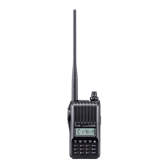
Icom IC-T70A Service Manual
Vhf/uhf dual band fm transceiver
Hide thumbs
Also See for IC-T70A:
- Instruction manual (96 pages) ,
- Service manual (41 pages) ,
- Product review (3 pages)
Table of Contents
Advertisement
Advertisement
Table of Contents

Subscribe to Our Youtube Channel
Related Manuals for Icom IC-T70A


Summary of Contents for Icom IC-T70A
- Page 1 VHF/UHF DUAL BAND FM TRANSCEIVER S-14623XZ-C1 Feb. 2010...
- Page 2 8. READ the instructions of the test equipment throughly before connecting it to the transceiver. Icom, Icom Inc. and the Icom logo are registered trademarks of Icom Incorporated (Japan) in Japan, the United States, the United Kingdom, Germany, France, Spain, Russia and/or other countries.
-
Page 3: Table Of Contents
TABLE OF CONTENTS SECTION SPECIFICATIONS SECTION INSIDE VIEWS SECTION DISASSEMBLY INSTRUCTION SECTION CIRCUIT DESCRIPITON RECEIVER CIRCUITS............4-1 TRANSMITTER CIRCUITS . -
Page 4: Specifications
Less than 0.18 μV • Power supply : 10.0–16.0 V DC for external DC power, Other frequency range Less than 0.32 μV or specified Icom’s battery pack • Audio output power (at 10% distortion/7.2 V DC) • Current drain (at 7.2 V DC) - Page 5 SECTION 2. INSIDE VIEWS • MAIN UNIT (TOP VIEW) TX AMP CURRENT DETECTER (IC102) DC SW (VCC line) (Q100) 5 V REGULATOR (BTL5V line) (Q6) 5 V REGULATOR (5VS line) (Q108) TX PWR AMP (Q507) 5 V REGULATOR (T5 line) (Q200) AF AMP/BPF/LPF TX DRIVE AMP...
- Page 6 • MAIN UNIT (BOTTOM VIEW) AF POWER AMP ANT SW DRIVER (IC1) (Q508) POWER SUPPLY LINE “CHG” SW (Q101) RF AMP (UHF band) POWER SUPPLY (Q511) LINE “BTL5V” SW RF AMP (VHF band) (Q5) (Q505) MIC LINE SW (Q7) TX MUTE SW (Q504) POWER SUPPLY LINE “5VS”...
-
Page 7: Disassembly Instruction
1) Remove the jack cap, ANT nut and 2 knobs. 1) Remove the metal sheet from the top plate. 2) Unsolder the 5 points, and remove the shield plate. Remove with; Top plate Metal sheet “ICOM Driver (Q)” (8960000370) ANT NUT SCREWS UNSOLDER... -
Page 8: Circuit Descripiton
SECTION 4. CIRCUIT DESCRIPTION 4-1 RECEIVER CIRCUITS DUPLEXER 1ST IF CIRCUITS The VHF/UHF RX signal from the antenna is separated by The signal from the RF circuits is applied to the 1st IF frequency in the duplexer. The VHF signal is passed through mixer (VHF band;... -
Page 9: Transmitter Circuits
2ND IF AND DEMODULATOR CIRCUITS 4-2 TRANSMITTER CIRCUITS The signal from the 1st IF circuits is applied to the IF TX AF CIRCUITS demodulator IC (IC313), which contains the 2nd IF mixer, The audio signal from the internal or external microphone 2nd IF AMP, FM detector, etc. -
Page 10: Frequency Synthesizer Circuits
TRANSMIT AMPLIFIERS • VHF BAND The TX signal is passed through the LPFs and ANT SW The TX signal from the LO SW (D319) is passed through (D509–D511), before being fed to the antenna. the attenuator (D500 and D501), which continuously adjusts the TX signal in level to keep it constant. -
Page 11: Cpu Port Allocation
4-4 CPU PORT ALLOCATION LINE LINE DESCRIPTION DESCRIPTION NAME NAME RX AF line switch (IC904) control. [POWER ] input. 54 DETMUTE PWRSW L=Pushed. L=AF mute (The quelch is closed). Transmission mute. 2–5 KS3–KS0 TXMUTE Key matrix. L=TX mute. 6–9 KR3–KR0 MIC mute switch (IC909) control. -
Page 12: Adjustment Procedures
SECTION 5. . ADJUSTMENT PROCEDURE 5-1 PREPARATION ¤ REQUIRED EQUIPMENTS EQUIPMENT GRADE AND RANGE EQUIPMENT GRADE AND RANGE DC cable OPC–254L (Optional product) JIG cable See the page 5-1. Measuring range : 0.1–10 W Frequency range : 0.1–600 MHz RF power meter Frequency range : 100–600 MHz Frequency counter... - Page 13 ¤ ENTERING ADJUSTMENT MODE 1) Turn the transceiver's power OFF. 2) Connect the JIG cable "#1" (See the page 5-1) to the [SP] jack. 3) While pushing [SET], [BAND] and [V/M/C], turn the transceiver's power ON. JIG CABLE #1 (See the page 5 -1.) To [SP] [V/M/C] [SET]...
-
Page 14: Transmit Adjustments
5-2 TRANSMIT ADJUSTMENTS 1) Select an adjustment item using [VOL]. 2) Set or modify the adjustment value as specifi ed using [DIAL], then push [BAND] to store the adjustment value. TRANSCEIVER’S ADJUSTMENT ADJUSTMENT OPERATION VALUE CONDITION ITEM TX DRIVE AMP 1 •... - Page 15 5-2 TRANSMIT ADJUSTMENTS (Continued) 1) Select an adjustment item using [VOL]. 2) Set or modify the adjustment value as specifi ed using [DIAL], then push [BAND] to store the adjustment value. TRANSCEIVER’S ADJUSTMENT ADJUSTMENT OPERATION VALUE CONDITION ITEM TX OUTPUT 1 •...
- Page 16 5-2 TRANSMIT ADJUSTMENTS (Continued) 1) Select an adjustment item using [VOL]. 2) Set or modify the adjustment value as specifi ed using [DIAL], then push [BAND] to store the adjustment value. TRANSCEIVER’S ADJUSTMENT ADJUSTMENT OPERATION VALUE CONDITION ITEM TX DRIVE AMP 1 •...
- Page 17 5-2 TRANSMIT ADJUSTMENTS (Continued) 1) Select an adjustment item using [VOL]. 2) Set or modify the adjustment value as specifi ed using [DIAL], then push [BAND] to store the adjustment value. TRANSCEIVER’S ADJUSTMENT ADJUSTMENT OPERATION VALUE CONDITION ITEM TX OUTPUT 1 •...
-
Page 18: Frequency Adjustments
5-3 FREQUENCY ADJUSTMENTS 1) Select an adjustment item using [VOL]. 2) Set or modify the adjustment value as specifi ed using [DIAL], then push [BAND] to store the adjustment value. ADJUST- TRANSCEIVER’S ADJUSTMENT OPERATION MENT VALUE CONDITION ITEM REFERENCE 1 • Frequency: Displayed •... -
Page 19: Moduration Adjustments
5-4 MODURATION ADJUSTMENTS 1) Select an adjustment item using [VOL]. 2) Set or modify the adjustment value as specifi ed using [DIAL], then push [BAND] to store the adjustment value. ADJUST- TRANSCEIVER’S ADJUSTMENT OPERATION MENT VALUE CONDITION ITEM FM (Wide) 1 •... - Page 20 5-4 MODURATION ADJUSTMENTS (Continued) 1) Select an adjustment item using [VOL]. 2) Set or modify the adjustment value as specifi ed using [DIAL], then push [BAND] to store the adjustment value. ADJUST- TRANSCEIVER’S ADJUSTMENT OPERATION MENT VALUE CONDITION ITEM FM (Narrow) 1 •...
- Page 21 5-4 MODURATION ADJUSTMENTS (Continued) 1) Select an adjustment item using [VOL]. 2) Set or modify the adjustment value as specifi ed using [DIAL], then push [BAND] to store the adjustment value. TRANSCEIVER’S ADJUSTMENT ADJUSTMENT OPERATION VALUE CONDITION ITEM TONE DEVIATION 1 •...
-
Page 22: Receive Adjustments
5-5 RECEIVE ADJUSTMENTS 1) Select an adjustment item using [VOL]. 2) Set or modify the adjustment value as specifi ed using [DIAL], then push [BAND] to store the adjustment value. TRANSCEIVER’S ADJUSTMENT ADJUSTMENT OPERATION VALUE CONDITION ITEM RX SENCITIVITY 1 NOTE: When "RX SENSITIVITY" is re-adjusted, "S-METER" must be re-adjusted too. 136 MHz band •... - Page 23 ¤ CONNECTION STANDARD SIGNAL GENERATOR (0.1 – 600 MHz) SETTING; Modulation : 1 kHz Deviation : ±3.5 kHz • POWER SUPPLY VOLTAGE METER “7.2 V” − AMMETER – − – DC power supply 6–10 V/3 A 5 - 12...
-
Page 24: Parts List
SECTION 6. PARTS LIST [MAIN UNIT] [MAIN UNIT] PARTS PARTS DESCRIPTION DESCRIPTION LOCATION LOCATION 1110007610 S.IC TPA0211DGNR 12.1/36.6 D257 1750001810 S.DIO L1SS400T1G <SLVJ> [EUR] T 72.5/2.4 1110006470 S.IC LMV324IPWR 34/29.1 1750001810 S.DIO L1SS400T1G <SLVJ> [UK] 1110007200 S.IC M61545AFP#DF0R 37.9/38.3 1750001810 S.DIO L1SS400T1G <SLVJ>... - Page 25 [MAIN UNIT] [MAIN UNIT] PARTS PARTS DESCRIPTION DESCRIPTION LOCATION LOCATION L311 6200013750 S.COI MLK1005SR10JT 48.2/14.5 7030005090 S.RES ERJ2GEJ 104 X (100K) 38.8/41.6 L312 6200005140 S.COI MLF1608D R33K-T 59.7/43.4 7030000100 S.RES MCR10EZHJ 4.7 (4R7) 21.7/42 L313 6200009351 S.COI ELJRE R22GFA 41.9/14.6 7030000100 S.RES MCR10EZHJ 4.7 (4R7) 20/42 L314...
- Page 26 [MAIN UNIT] [MAIN UNIT] PARTS PARTS DESCRIPTION DESCRIPTION LOCATION LOCATION R256 7030010040 S.RES ERJ2GEJ-JPW 95.9/38.7 R393 7030005000 S.RES ERJ2GEJ 471 X (470) 59.4/44.5 R300 7030005210 S.RES ERJ2GEJ 822 X (8.2K) 58.4/14.9 R395 7030005040 S.RES ERJ2GEJ 472 X (4.7K) 42.8/12.8 R301 7030007320 S.RES ERJ2GEJ 225 X (2.2M) 54.5/33.1 R396...
- Page 27 [MAIN UNIT] [MAIN UNIT] PARTS PARTS DESCRIPTION DESCRIPTION LOCATION LOCATION R817 7030004970 S.RES ERJ2GEJ 470 X (47) 44.9/12.9 C109 4030019740 S.CER C1005 JB 1H 102K-T 24.2/30.3 R818 7030005220 S.RES ERJ2GEJ 223 X (22K) 45/15.3 C110 4030019810 S.CER C1005 JB 1E 103K-T 76.8/11.8 R819 7030005050 S.RES ERJ2GEJ 103 X (10K)
- Page 28 [MAIN UNIT] [MAIN UNIT] PARTS PARTS DESCRIPTION DESCRIPTION LOCATION LOCATION C290 4030009770 S.CER C1005 CH 1H 220J-T 69/13 C417 4030019740 S.CER C1005 JB 1H 102K-T 36.5/25.7 C300 4030019970 S.CER C1005 JB 0J 105K-T 54.5/30.2 C418 4030009740 S.CER C1005 CH 1H 100C-T 58.1/33.9 C301 4030019970 S.CER C1005 JB 0J 105K-T...
- Page 29 [MAIN UNIT] [MAIN UNIT] PARTS PARTS DESCRIPTION DESCRIPTION LOCATION LOCATION C584 4030020100 S.CER GQM1882C1H110GB01D (G) C650 4030011640 S.CER C1005 CH 1H 010B-T 10.5/9.2 [EUR] T 20.4/11.9 C651 4030011700 S.CER C1005 CH 1H 040B-T 5.8/11.6 4030020100 S.CER GQM1882C1H110GB01D (G) C652 4030009770 S.CER C1005 CH 1H 220J-T 8/2.6 [UK] C653...
- Page 30 SECTION 7. MECHANICAL PARTS [CHASSIS PARTS] [ACCESSORIES] ORDER ORDER DESCRIPTION QTY. DESCRIPTION QTY. 3310002150 FA-S270C 6510025010 SMA-R2869 (Optional) BC-167SD [EUR], [EXP-01], [RSP] (Optional) BC-167SA [TPE], [USA], [EXP] 2510001550 K036NA511-10 (Optional) BC-167SV [AUS] (Optional) BP-264 EXP 8900016360 OPC-1190A 8010011960 STRAP HK-005 8010021690 3253 CHASSIS (Optional) MB-124...
- Page 31 MP13 (C) MP17 (C) MP28(C) J1(C) MP21(C) MP36(C) MP1(C) MP10(C) MP25(C) MP26(C) MP22(C)×2 MP301(M) MP34(C) S270(M) MP37(C) MP26(C) MP9(C) MP39(C) MP24(C) MC1(M) MP23(C) MP26(C) SP1(C) MP38(C) MP11(C) MP27(C) MP31(C) MP8(C) DS204(M) MP26(C) W1(C) MP20(C) MP19(C) MP3(C) MP5(C) MP29(C) MP12(C) MP6 (C) EP52(M) MP4(C) MP7 (C)
- Page 32 The combination of top side and bottom side of this SECTION 8. BOARD LAYOUTS J100 • MAIN UNIT (TOP VIEW) R200 R208 R207 DS201 DS200 C241 R225 C950 EP104 C101 C952 EP100 D100 C108 C130 R212 R137 D106 C806 C206 C104 R132 C127...
- Page 33 The combination of top side and bottom side of this • MAIN UNIT (BOTTOM VIEW) R827 D103 R826 C392 C124 D104 C395 R384 R121 D313 R811 C405 R130 C134 C118 C407 C116 D109 C240 D265 Q102 R393 Q107 EP505 [DIAL]•[VOL] R635 R234 IC311...
- Page 34 SECTION 9. BLOCK DIAGRAM MAIN UNIT (1/2) BTL5V IC1:TPA0211 DETO DETO MUTE J700 IC4:M61545AFP Q8:XP6501 IC904:TC7S66FU AFSTBY VOLCK,VOLDA DETMUTE IC5:R2A20178 BEEP/DTMF CTCIN TONE DADI,DACLK,DALD SP1: Q10:XP6501 K036NA511 CHASSIS IC4:M61545AFP IC909:TC7S66 MUTE IC800B:NJM2746 IC2A:LMV324 IC2D:LMV324 MC1: RTONE EM6022P VOLCK,VOLDA MMUTE BEEP/DTMF Q7:LDTC144 Q4:2SA1832 CONT...
- Page 35 MAIN UNIT (2/2) R5T5 Q510:LDTC144 TTEMP D508:1SV271 D513:1SV271 D525:1SV271 LO AMP TEMP VCO_MUTE MUTE Q307:LDTC144 D318: DAN222 VCC-I VVCO5 VVCO5 D500:JDP2S04E D524:1SV308 TX:400.000M~479.000MHz D501:JDP2S04E D506:1SV307 RX:400.000M~479.000MHz VCOMOD Q503:RFM01U7P Q507:RFM12U7X Q502:2SC5998 TX_LO DRIVE BUFF D304:HSC365 Q314:2SC5231 Q512:2SC5231 D319:1SV308 D305:HVC365 D311:HSC277 D312:HSC277 PLL3.6V D306:HVC365 Q311:2SC5231...
- Page 36 SECTION 10. VOLTAGE DIAGRAM MAIN UNIT (1/4) R825 5.45V 7.18V BTL5V R826 6.55V 2.73V SDRS-3650P-008A R827 MMZ1608Y121B T XP1501 2.73V TPA0211DGN 4.48V 4.97V BYPASS 5.14V SE/BTL SHUTDOWN MMZ1005Y102CT MMZ1608Y121BT 4.7k AFSTBY CLOUT CLIN MMUTE LDTC144TE CTCOUT VCOMOD BPF3 BPF1 5.00V 2.49V 2.50V 13 VIN6...
- Page 37 MAIN UNIT (2/4) AF FILTER TONE FILTER 0.69V 6.8k 2.62V 2.2M 2.07V 0.0027 0.0018 0.01 UVCO_SEL C952 0.70V R222 0.033 0.033 1.46V 2.04V Q204 IC908 VVCO_SEL 4.96V 0.13V 0.11V XP4601 1.60V 100k LDTC144EE C241 0.0033 D TCS 0.80V R611 0k Q’S TX FILTER CD4094BPWR...
- Page 38 MAIN UNIT (3/4) TTEMP 3.50V VCC- I 2.78V C367 L305 0.75V 100P R376 C383 5.00V R335 Q306 Q310 LDTC144EE 4.22V 2SC5108 PLLSW VHF VCO VHFC 3.92V 0.82V(SHIFT ON) TXMUTE R302 R325 (145MHz) 3.42V(SHIFT OFF) 3.00V 3.3k 4.16V UHFC R326 R328 R339 L302 HVC365...
- Page 39 MAIN UNIT (4/4) V TX:2.02V V TX:3.97V V TX:2.02V U TX:3.50V U TX:0V U TX:3.82V TTEMP RX:0V RX:0V RX:0V Q510 LDTC114EE R564 EP503 7.20V J500 MPZ1608S101A R568 R561 VCC- I C605 C623 C610 C604 NTCG10 470 P D525 0.001 R570 0.001 MMZ2012Y102B C566...
- Page 40 Highway 17 Delta, B.C., V4K 5B8, Canada : http://www.icomspain.com Phone : +1 (604) 952-4266 Fax : +1 (604) 952-0090 E-mail : icom@icomspain.com : http://www.icomcanada.com E-mail : info@icomcanada.com Blacksole House, The Boulevard, Altira Business Park, Herne Bay, CT6 6GZ, UK Phone : +44 (01227) 741741...
- Page 41 S-14623XZ-C1 1-1-32, Kamiminami, Hirano-ku, Osaka 547-0003, Japan © 2010 Icom Inc.
Need help?
Do you have a question about the IC-T70A and is the answer not in the manual?
Questions and answers