
Subscribe to Our Youtube Channel
Related Manuals for Zamboni FastICE DK - 11000

Summary of Contents for Zamboni FastICE DK - 11000
- Page 1 Zamboni FastICE ® Ice Making System Operating Manual FastICE ® is a registered trademark of Frank J. Zamboni & Co., Inc. © Zamboni Company...
-
Page 2: Table Of Contents
SCREEN NAVIGATION MAP ................... MACHINE MODES ....................Test Mode ......................Automatic Mode ....................Automatic Boom Shut-off ..................Safety and Functional Interlocks ................OPERATOR INTERFACE .................... Boot Screen ......................Zamboni FastICE ® Operating Manual DK - 11000 Page 2 of 44... - Page 3 Chapter 3 – Operating Procedures: Standard Ice Resurfacing ......Chapter 4 – Operating Procedures: Ice Building ............ Chapter 5 – Recommended Regular System Maintenance ........Chapter 6 - System Troubleshooting ..............Zamboni FastICE ® Operating Manual DK - 11000 Page 3 of 44...
- Page 4 Lower Boom ONLY Alarm Limit Diagram ............... Operating Region Identification Diagram ............... Upper Boom ONLY Alarm Limit Diagram ............... Both Booms ON Alarm Limit Diagram ..............Revisions ....................... Zamboni FastICE ® Operating Manual DK - 11000 Page 4 of 44...
-
Page 5: Chapter 1 - System Description
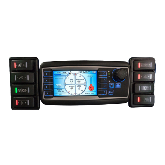
• Upper and lower spray booms • Board spray valve • Electrically controlled, diaphragm type water control valves (1 each for the Upper boom, Lower boom, and Board Spray Valve) Zamboni FastICE ® Operating Manual DK - 11000 Page 5 of 44... - Page 6 Operating Manual Master Power Switch USB Data Port SWITCH BANK 1 SWITCH BANK 2 Figure 1: FastICE Pro package with switch banks and display Zamboni FastICE ® Operating Manual DK - 11000 Page 6 of 44...
-
Page 7: Switch Bank 1
UPPER BOOM WATER CONTROL (ON-OFF) LOWER BOOM WATER CONTROL (ON-OFF) WATER APPLICATION RATE SCALING (DECREASE – HOLD – INCREASE) WATER BLAST FUNCTION Figure 3: FastICE Switch Bank 2 switch and LED identification Zamboni FastICE ® Operating Manual DK - 11000 Page 7 of 44... -
Page 8: Switch Bank 1
White blinking light when the left hand light is Red. The details of the blink codes are detailed in the “Troubleshooting” section of this manual. Zamboni FastICE ® Operating Manual... -
Page 9: Switch Bank 2
Each press of the switch will change the spray flow 5 percentage points to a maximum of 50% (10 presses). The switch will only blink when pushed. Board Spray (OFF-ON) • This switch controls water flow out of the Board Spray Valve. Zamboni FastICE ® Operating Manual DK - 11000... -
Page 10: Blast (Off-On)
The target water flow rate for a given driving speed can be increased or decreased by up to 50% by turning the adjustment knob on the display or by depressing the rocker switch for flow scaling. Zamboni FastICE ® Operating Manual... -
Page 11: Display Controls
Switch bank 2 (only when the display is on the Dashboard screen). Either the knob or switch may be used to make the adjustment based on the operator’s preference. DISPLAY CONTROLS Zamboni FastICE ® Operating Manual DK - 11000... -
Page 12: Screen Navigation Map
Active adjustment of the Scaling function using the encoder knob will be provided to the operator as an alternate means of adjustment to the switch panel. Either method may be used at any time during operation at the operator’s discretion. The SUMMARY screen will display average readings (passive read-out): Zamboni FastICE ® Operating Manual DK - 11000... - Page 13 Controller Software Version The HIDDEN screen may be accessed only from the Set-Up screen and when the Function key is pressed for 5-seconds and released. When active, it will display and allow selection (using encoder knob) of: Zamboni FastICE ® Operating Manual...
-
Page 14: Machine Modes
The threshold speed is labelled UPPER BOOM SHUT- OFF SPEED and is set on the Set-up Screen. The boom will turn back on when ground speed exceeds the set threshold speed. Zamboni FastICE ® Operating Manual... -
Page 15: Safety And Functional Interlocks
A moving average calculation is performed on the water level sensor signal to prevent rapid off/on due to water sloshing in the tank. Re-filling the tank so the level holds above 0% for at least 5 seconds will reset this interlock and allow the pump to start. Zamboni FastICE ® Operating Manual DK - 11000... -
Page 16: Operator Interface
Boot Screen The Boot Screen is displayed while the display is booting up. It is the first screen displayed. When the display program starts to load, the display will change to the Load Screen. Zamboni FastICE ® Operating Manual DK - 11000... -
Page 17: Load Screen
The Dashboard Screen provides a read-out of real time operational performance. This is a mostly passive display – interaction is allowed only for Scaling (Water Flow Adjustment), using the encoder knob as an alternate to the control switch. Zamboni FastICE ® Operating Manual... -
Page 18: Summary Screen
These values are available to download via USB port mounted on the machine’s dash. Operator interaction is only allowed to reset summary statistics and to download summary information via USB. Zamboni FastICE ® Operating Manual DK - 11000... -
Page 19: Set-Up Screen
The Diagnostics Screen will display the status of the hydraulic valve coil and the three water valve coils regardless of whether or not the system is in use. Supply voltage will also be monitored for troubleshooting purposes. Zamboni FastICE ® Operating Manual... -
Page 20: Machine Parameters Screen (Technical Set-Up, Hidden Screen)
Box highlighting will change back to red after entering the new value and rotating the knob will move the box to the next parameter. Exit the Machine Parameters screen by pressing the Home key (returns to the Dashboard screen). Zamboni FastICE ® Operating Manual... -
Page 21: Function Lockout On Parameters Screen
“unlocked” appearance to a “locked” appearance, as shown here: To unlock a system that has been locked, press and hold the Function key for 5 seconds, after which time the pad lock symbol will change from “locked” to “unlocked”. Zamboni FastICE ® Operating Manual... -
Page 22: Fault Notification Pop-Ups On The Fastice Display
“on” position. When a pop-up displays, the operator may clear the screen by pressing the ESC key. Zamboni FastICE ® Operating Manual... -
Page 23: Display Pop-Up System Fault Messages
The default setting for this is 70 kPa (~10 PSI) above the target value for at least 10 seconds. For reference, the spray pressure for a traveling speed of 8 km/hr (5 MPH) and a flow rate of 54.1 L/ min (14.3 GPM) is 138 kPa (20 PSI). Zamboni FastICE ® Operating Manual... -
Page 24: System Fault: Water Pressure Out Of Range: Low
Problems may include: • Hydraulic control valve contamination in the FastICE hydraulic manifold • Damaged water flow meter Zamboni FastICE ® Operating Manual DK - 11000 Page 24 of 44... -
Page 25: System Fault: Water Flow And Pressure Out Of Range: Low
Leaking hose connection between the pump and flow meter • Insufficient pump speed and maximum command signal is being sent to hydraulic valve but water flow is too low Zamboni FastICE ® Operating Manual DK - 11000 Page 25 of 44... -
Page 26: System Fault: Water Level Sensor Disconnected
If it does not detect a return current flow, it will activate a VALVE DISCONNECTED fault. There are (3) water control valves in the system: Upper Boom, Lower Boom and Board Spray. WATER VALVE DISCONNECTED! Zamboni FastICE ® Operating Manual DK - 11000... -
Page 27: System Fault: Hydraulic Valve Disconnected
VALVE DISCONNECTED fault. There are (3) water control valves in the system: Upper Boom, Lower Boom and Board Spray. HYDRAULIC VALVE DISCONNECTED! Zamboni FastICE ® Operating Manual DK - 11000... -
Page 28: Chapter 2 - System Subassembly Description
The lower-most ball valve in the pump housing allows the pump housing to be fully drained, thereby preventing against pump damage due to freezing and expanding water. FastICE ® is a registered trademark of Frank J. Zamboni & Co., Inc. © Zamboni Company... -
Page 29: Water Valve Manifold Assembly
1 second period, the current is reduced to an amount that is sufficient to keep the valve open. This method of controlling the valves reduces the overall energy requirements of the system. Zamboni FastICE ® Operating Manual... -
Page 30: Spray Boom Subassembly
(2) quick disconnect couplings for the water hoses, disconnecting the connector for the board spray valve, and pulling the (2) orange handle pull pins that are secured to the spray boom support structure with clip rings: Here is a closer illustration of the pull-pins: Zamboni FastICE ® Operating Manual DK - 11000... - Page 31 Likewise, these valves allow a fully filled spray boom to be drained for overnight storage in cold environments: Zamboni FastICE ® Operating Manual DK - 11000...
-
Page 32: Chapter 3 - Operating Procedures: Standard Ice Resurfacing
Operating Manual Chapter 3 – Operating Procedures: Standard Ice Resurfacing The following provides direction on how to use the Zamboni FastICE system to perform a standard ice resurfacing. 1. Fill the Ice Making Water tank to between 50% and 100% full. The amount of water in the tank should be determined by how much ice thickness you plan to build. - Page 33 Drain the Ice Making Water tank at the end of the ice resurfacing session. We recommend that the tank be filled only to what will be used during the resurfacing session to guarantee that only hot water is used to make ice. Zamboni FastICE ® Operating Manual...
-
Page 34: Chapter 4 - Operating Procedures: Ice Building
Operating Manual Chapter 4 – Operating Procedures: Ice Building The following provides direction on how to use the Zamboni FastICE system to perform an Ice Building operation. 1. Fill the Ice Making Water tank to 100% full. 2. Turn Master Power Switch ON 3. -
Page 35: Chapter 5 - Recommended Regular System Maintenance
The water filter should be purged using the removable cap once per week, and the filter element should be inspected for debris once every 2 weeks. Also, we recommend that the Ice Making Water tank be fully drained and rinsed out once every 2 weeks to ensure proper system performance. Zamboni FastICE ® Operating Manual DK - 11000... -
Page 36: Chapter 6 - System Troubleshooting
Operating Manual Chapter 6 - System Troubleshooting The Zamboni FastICE system features ability for self-diagnosis in the event that it is not performing as expected. If a fault condition is activated, the fault can be cleared by cycling the main power switch on the side of the display enclosure off and then on again. - Page 37 3. Solenoid coil on the valve 4. Inspect valve solenoid coil for exposed to over-voltage / over- damage current and is damaged 5. Verify valve solenoid coil resistance to be 4.5 Ohms Zamboni FastICE ® Operating Manual DK - 11000 Page 37 of 44...
- Page 38 Water flow and pressure are lower Pressure Low than the target operating point by the alarm limit for at least 10 seconds, but the spray pressure is within range Zamboni FastICE ® Operating Manual DK - 11000 Page 38 of 44...
- Page 39 The water pump will not start unless the control system detects a water level in the tank greater than 0%. The ability for self-diagnosis is not comprehensive, so some failures may require proper troubleshooting practices, such as “divide and conquer”, “ruling out”, and “elimination”. Zamboni FastICE ® Operating Manual DK - 11000...
-
Page 40: Water Flow And Pressure Fault Criteria Reference Diagrams
Lower Boom ONLY Alarm Limit Diagram 1. Water Pressure High Alarm Limit 2. Water Pressure Low Alarm Limit 3. Water Flow Low or High Alarm Limit Zamboni FastICE ® Operating Manual DK - 11000 Page 40 of 44... -
Page 41: Operating Region Identification Diagram
(using the lower boom flow curve as the example) 4. Water Pressure High operating region 5. Water Pressure Low operating region 6. Water Flow Low or High operating region 7. Water Flow and Pressure Low Zamboni FastICE ® Operating Manual DK - 11000 Page 41 of 44... -
Page 42: Upper Boom Only Alarm Limit Diagram
Operating Manual Upper Boom ONLY Alarm Limit Diagram 1. Water Pressure High Alarm Limit 2. Water Pressure Low Alarm Limit 3. Water Flow Low or High Alarm Limit Zamboni FastICE ® Operating Manual DK - 11000 Page 42 of 44... -
Page 43: Both Booms On Alarm Limit Diagram
Operating Manual Both Booms ON Alarm Limit Diagram 1. Water Pressure High Alarm Limit 2. Water Pressure Low Alarm Limit 3. Water Flow Low or High Alarm Limit Zamboni FastICE ® Operating Manual DK - 11000 Page 43 of 44... -
Page 44: Revisions
Operating Manual Revisions Revision Date Revision Description 31/7/2018 Initial production release Zamboni FastICE ® Operating Manual DK - 11000 Page 44 of 44...
Need help?
Do you have a question about the FastICE DK - 11000 and is the answer not in the manual?
Questions and answers