Table of Contents
Advertisement
Quick Links
Advertisement
Table of Contents

Subscribe to Our Youtube Channel
Summary of Contents for URC Total Control MRX-5
- Page 1 MRX-5 Total Control Owner’s Manual MRX-5 Owner’s Manual...
-
Page 2: Table Of Contents
Specifications ....................................................8 Limited Warranty Statement................................................8 Technical Suppor t Toll Free: 800-904-0800 Main: 914-835-4484 techsupport@urc-automation.com H o u r s : 9 : 0 0 a m - 5 : 0 0 p m E S T M - F Rev 1.0... -
Page 3: Introduction
MRX-5 Total Control Owner’s Manual Introduction The MRX-5 Advanced Network System Controller controls is designed to meet the needs of residential or small commercial environments. Only Total Control software, products, and user interfaces are supported by this powerful device. This device is not compatible with Total Control 1.0 legacy products. Features and Benefits •... -
Page 4: Front Panel Description
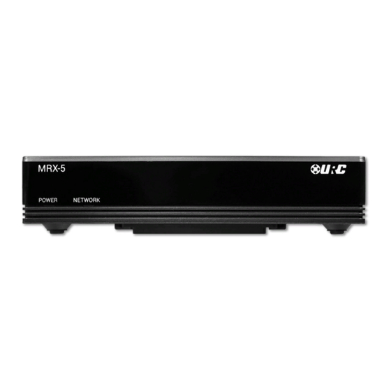
MRX-5 Total Control Owner’s Manual Front Panel Description The front panel of the MRX-5 Advanced Network System Controller displays the following information: 1. Power LED: Indicates three (3) possible states: 2. Network LED: Indicates three (3) possible states: ■ Solid Blue: The device is receiving power and has successfully ■... -
Page 5: Rear Panel Description
2. IR Outputs: Four (4) standard 3.5mm IR emitter ports. IR Output 4 provides local network. variable level adjustment. 3. RS-232 Port: One (1) RS-232 ports support Tx(Transmit), Rx(Receive) and GND(Ground) connections for two way communication. Compatible with URC cables RS232F and RS232M. -
Page 6: Bottom Panel Description
MRX-5 Total Control Owner’s Manual Bottom Panel Description The bottom panel of the MRX-5 Advanced Network System Controller displays the following information: 1. Reset Button: Located at the bottom of the device and requires a stylus or paper clip to press. Performs two (2) possible actions: 2. -
Page 7: Installing The Mrx-5
1. Connect an Ethernet cable (RJ45) to the rear of the MRX-5 and the onto an available LAN port of the network’s local router (Luxul preferred). 2. A certified URC integrator is required for this step, configure the MRX-5 to a DHCP/MAC reservation within the local router. -
Page 8: Connecting Ir Emitters
MRX-5 Total Control Owner’s Manual Connecting IR Emitters IR emitters are used to communicate to AV devices such as cable boxes, televisions, blu-ray players and more. 1. Plug IR Emitters (four (4) supplied in the box) into any of the four (4) IR outputs available on the rear of the MRX-5. -
Page 9: Connecting Rs-232 (Serial)
The MRX-5 can operate equipment via RS-232 communication. The allows discrete serial commands to be triggered from the Total Control system. Connect an RS-232 device using URC’s proprietary RS-232 cables. These use either male or female DB-9 connections with standard pin-outs. -
Page 10: Specifications
Owner’s Manual Specifications Network: One (1) 10/100 RJ45 Ethernet port (two LED indicators) Limited Warranty Statement https://www.urc-automation.com/legal/warranty-statement/ Processor: ARM9 Thumb Processor 400 MHz End User Agreement RAM: DDR2 256 MB The terms and conditions of the End User Agreement available at https://www.urc-automation.com/legal/end-user-agreement/... - Page 11 MRX-5 Total Control Owner’s Manual Warning! The manufacturer is not responsible for any Radio or TV interference caused by unauthorized modifications to this equipment. Changes or modifications not expressly approved by the manufacturer could void the user's authority to operate the equipment. Regulatory Information to the User •...


Need help?
Do you have a question about the Total Control MRX-5 and is the answer not in the manual?
Questions and answers