Table of Contents
Advertisement
Quick Links
Advertisement
Table of Contents

Summary of Contents for URC Total Control MRX-5
- Page 1 MRX-5 Total Control Owner’s Manual MRX-5 Owner’s Manual...
-
Page 2: Table Of Contents
End User Agreement: ..................................................11 Federal Communication Commission Interference Statement:....................................12 Technical Suppor t Toll Free: 800-904-0800 Main: 914-835-4484 techsupport@urc-automation.com H o u r s : 9 : 0 0 a m - 6 p m E S T M - F... -
Page 3: Overview
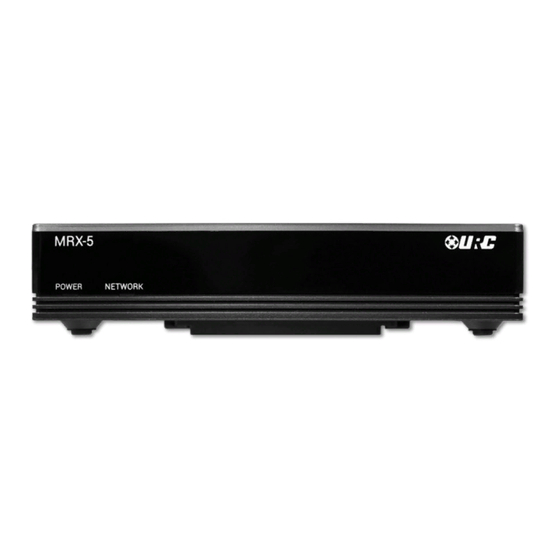
The MRX-5 Advanced Network System Controller can ONLY be configured using Total Control software that is ONLY distributed to certified URC integrators. Features & Benefits: • Stores the Total Control system’s programming (single zone) including device commands, macros, events, and much more! •... -
Page 4: Parts List
MRX-5 Total Control Owner’s Manual Parts List Below is included with MRX-5:... -
Page 5: Front Panel Descriptions
MRX-5 Total Control Owner’s Manual Front Panel Descriptions: The front panel of the MRX-5 Advanced Network System Controller displays the following information: 1. Power LED: Indicates three (3) possible states: 2. Network LED: Indicates three (3) possible states: • Solid Blue: The device is receiving power and has successfully booted up. •... -
Page 6: Rear Panel Descriptions
2. IR Outputs: Four (4) standard 3.5mm IR emitter ports. IR Output 4 provides variable level adjustment. 3. RS-232 Port: One (1) RS-232 ports support Tx(Transmit), Rx(Receive) and GND(Ground) connections for two way communication. Compatible with URC cables RS232F and RS232M. -
Page 7: Bottom Panel Descriptions
MRX-5 Total Control Owner’s Manual Bottom Panel Descriptions: The bottom panel of the MRX-5 Advanced Network System Controller displays the following information: 1. Reset Button: Located at the bottom of the device and requires a stylus or 2. Mounting Plate: Slide the mounting plate up or down to remove it from the paper clip to press. -
Page 8: Installing The Mrx-5
1. Connect an Ethernet cable (RJ45) to the rear of the MRX-5 and the onto an available LAN port of the network’s local router (Luxul preferred). 2. A certified URC integrator is required for this step, configure the MRX-5 to a DHCP/MAC reservation within the local router. -
Page 9: Connecting Ir Emitters
MRX-5 Total Control Owner’s Manual Connecting IR Emitters: IR emitters are used to communicate to AV devices such as cable boxes, televisions, blu-ray players and more. 1. Plug IR Emitters (four (4) supplied in the box)into any of the four (4) IR outputs available on the rear of the MRX-5. -
Page 10: Connecting Rs-232 (Serial)
The MRX-5 can operate equipment via RS-232 communication. The allows discrete serial commands to be triggered from the Total Control system. Connect RS-232 device using URC’s proprietary RS-232 cables. These use either male or female DB-9 connections with standard pin-outs. -
Page 11: Specifications
(2) years from the date of purchase by the end-user, but no longer than forty- RAM: DDR2 256 MB eight (48) months from the date of shipment of the URC equipment by URC to an authorized URC dealer or distributor. - Page 12 HEREIN. In the event of any warranty claim, URC will, at its sole option, repair the CERTAIN IMPLIED WARRANTIES, INCLUDING AN IMPLIED WARRANTY OF URC equipment using new or comparable rebuilt parts, or exchange the URC MERCHANTABILITY AND FITNESS FOR A PARTICULAR PURPOSE, MAY BE equipment for new or rebuilt equipment.
-
Page 13: End User Agreement
The terms and conditions of the End User Agreement are available at: THE POSSIBILITY OF SUCH DAMAGES. https://www.urc-automation.com/legal/end-user-agreement/ IN NO EVENT SHALL URC BE LIABLE FOR LOSS OF OR DAMAGE TO DATA, COMPUTER SYSTEMS OR COMPUTER PROGRAMS. URC’S LIABILITY, IF ANY, FOR DIRECT DAMAGES OF ANY FORM SHALL BE LIMITED TO ACTUAL DAMAGES, NOT IN EXCESS OF AMOUNTS PAID BY END USER FOR THE URC EQUIPMENT. -
Page 14: Federal Communication Commission Interference Statement
MRX-5 Total Control Owner’s Manual Federal Communication Commission Interference Statement: FCC Caution: This device complies with Part 15 of the FCC Rules. Operation is subject to the This equipment has been tested and found to comply with the limits for a Class B following two conditions: (1) this device may not cause harmful interference, and (2) digital device, pursuant to part 15 of the FCC Rules.


Need help?
Do you have a question about the Total Control MRX-5 and is the answer not in the manual?
Questions and answers