Table of Contents
Advertisement
Quick Links
Atmos
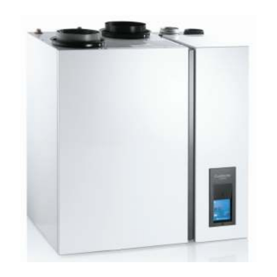
CombinAir
Settings and Maintenance of the CombinAir
Issue 13.8.10
Operation and commissioning:
The control unit on the front of the CombinAir is used to adjust the settings during commissioning.
The settings for the heat pump which need to be checked or adjusted during commissioning are shown
in colour. This document gives guidance on how to access and change the settings.
Advertisement
Table of Contents

Related Manuals for Atmos CombinAir


Summary of Contents for Atmos CombinAir
- Page 1 Issue 13.8.10 Operation and commissioning: The control unit on the front of the CombinAir is used to adjust the settings during commissioning. The settings for the heat pump which need to be checked or adjusted during commissioning are shown in colour. This document gives guidance on how to access and change the settings.
-
Page 2: Control Unit
Control unit Description Type Set button button Reset button button hot water button button hot water LED Status display 1 x 7 – segments display CH water display 2 x 7 – segments display... -
Page 3: User Program
USER PROGRAM The user program is identified by a permanently lit letter followed by a dot. Access Press the ‘Set’ button for 5 seconds until the letter C. appears • Next setting Press the ‘Set’ button • Different value Press the ‘Hot Water’ button •... - Page 4 Two temperature zones: Heat pump WDC without RT, gas boiler no WDC Two temperature zones: Heat pump WDC with RT, gas boiler WDC without Two temperature zones: Heat pump WDC with RT, gas boiler WDC with RT Two temperature zones: Heat pump WDC with RT, gas boiler no WDC Submenu CH- settings heat pump (LT zone)
- Page 5 Submenu sensor values To access the submenu sensor values go to setting b in the service settings menu (installer program) and press the hot water button. On the status display the sensor value b / A is alternately displayed. Pressing the set button will display the next sensor value.
- Page 6 Submenu CH settings heat pump To access to the submenu CH settings heat pump go to setting d in the service settings menu (installer program) and press the hot water button. On the status display the first setting d / h is alternately displayed. By pressing the set button the next setting is displayed.
- Page 7 Submenu CH settings gas boiler To access the submenu CH settings gas boiler go to setting E in the service settings menu (installer program) and press the hot water button. On the status display the first setting E / h is alternately displayed. By pressing the set button the next setting is displayed.
- Page 8 E / u WDC climate point at outside temperature – 15 ºC Adjustable in … WDC climate point at outside temperature – … ºC increments of WDC climate point at outside temperature – 10 ºC 1 ºC … WDC climate point at outside temperature – … ºC WDC climate point at outside temperature 0 ºC E / U...
-
Page 9: Warning Messages
WARNING, BLOCKING AND MALFUNCTION MESSAGES The Atmos CombinAir has three types of error messages: 1. Warning messages In this case, instead of the status message, a letter appears on the status display for one second, once every 5 seconds. 2. Blocking messages A permanently illuminated letter appears on the status display. -
Page 10: Blocking Messages
Appliance type recognition error; control unit is set to 38/80+ Appliance type recognition error; control unit is set to Combipact Appliance type recognition error; control unit is set to CombinAir Appliance type recognition error; control unit is set to CombinAirCool Malfunction messages A malfunction is an error which is so serious that the unit is locked. - Page 11 CAUSES OF MESSAGES Warning messages A warning is identified by a letter that appears on the status display every 5 seconds for a period of 1 second, instead of the status message. The appliance continues to operate, but the function to which the message applies will be switched off or ignored.
- Page 12 Appliance type recognition error; control unit is set to 38/80+ Appliance type recognition error; control unit is set to 24/33 Appliance type recognition error; control unit is set to CombinAir Appliance type recognition error; control unit is set to CombinAirCool...
- Page 13 System temperature sensor error (> 90 [° C], shorted) CC 01 This error code can only occur if the CombinAir is connected to a two-zone system. The boiler cannot support the heat pump with the result that the dwelling is not or insufficiently heated. This may be caused by air in the system or it can be caused by a software error in the control unit of the heat pump.
- Page 14 improperly connected • Air supply obstructed • Flue tube obstructed • Siphon obstructed • Ionisation cable not in order • Ionisation probe defective or causing short-circuit such as against the burner or heat exchanger • Ignition transformer defective • Ignition transformer electrical connection loose or improperly connected •...
- Page 15 • Control unit defective Safety internal malfunction in control unit • Control unit defective Letter Internal malfunction in control unit • Control unit defective (Dark Appliance receiving no mains power • Plug not inserted in wall socket display) • No electricity from wall socket •...
- Page 16 APPENDIX Electrical diagram for the control unit of the gas boiler section:...
Need help?
Do you have a question about the CombinAir and is the answer not in the manual?
Questions and answers