
Related Manuals for Atmos InterCombi


Summary of Contents for Atmos InterCombi
-
Page 1: Installation Instructions
Atmos InterCombi ATMOS ATMOS Installation Instructions Atmos Heating Systems West March Daventry Northants, NN11 4SA Tel: 01327 871990 Fax: 01327 871905 e-mail: sales@atmos.uk.com internet: www.atmos.uk.com Issue 1.4.05... - Page 2 © 2005 Atmos Heating Systems The information provided applies to the product in the standard model. Atmos Heating Systems can therefore not be held liable for any damage resulting from the product specifications that deviate from the standard model. The information provided has been compiled with the utmost care. However, Atmos Heating Systems cannot be held liable for any faults in the information nor for the consequences thereof.
-
Page 3: Table Of Contents
TABLE OF CONTENTS 1. Safety Regulations General ..................................7 CH system...................................7 Gas system .................................7 Electrical system .................................7 Domestic water system ...............................7 Flue discharge and air supply .............................7 2. Description of the Appliance General ..................................8 Operation ..................................8 Operating conditions ..............................8 PC interface ................................10 Test programmes ..............................11 2.5.1 Frost protection ..............................11... - Page 4 5.6.4 Outlet arrangements............................27 5.6.5 Flue discharge pipe and air supply pipe......................27 Outside wall outlet for twin pipe terminal - horizontal ....................28 Outside wall and roof outlet concentric terminal horizontal ..................30 Roof outlet combination and twin pipe terminal - vertical..................31 5.10 Roof outlet prefabricated chimney..........................34 5.11...
- Page 5 This manual Using this manual you can safely install and maintain this appliance. Carefully follow the instructions. In case of doubt, contact Atmos Heating Systems. Keep these instructions near the appliance. Abbreviations and names used Description To be referred to as...
- Page 6 Guarantee conditions Considering the conditions mentioned below, Atmos guarantees towards the recognised installer the soundness of the materials used, as well as the good operation of its Central Heating products, if applied for their intended use. When the occasion arises, we should be given the opportunity to ascertain ourselves, if necessary on the spot, of the validity of the guarantee claim.
-
Page 7: Safety Regulations
(Installation and Use) Regulations; October 1994. Failure to install appliances correctly could lead to prosecution. Atmos Heating Systems does not accept any liability for damage or injury caused by not (strictly) observing the current safety regulations and instructions, nor by negligence while installing the Atmos InterCombi wall- mounted gas heater and any accompanying accessories. -
Page 8: Description Of The Appliance
These are supplied separately. The Atmos InterCombi wall-mounted gas boiler has the CE quality mark and the Gas certification labels HE (Sedbuck A), SV , NZ (Solar compatible) and CW Class 5 (Hot water performance rating 1 to 6, where 6 is the highest) and IP44. - Page 9 Waiting position The LED of the on/off key and if necessary one of the LED’s of the domestic hot water comfort function are on. The appliance is ready for responding to the demand for CH or domestic hot water. 0 Pump overrun After the operation of the CH, the pump has an overrun.
-
Page 10: Pc Interface
During CH operation, the demanded CH supply temperature is displayed on the operating panel. The resistance R in the Electrical diagram can be removed when the room thermostat does not need any anticipation current. During CH operation, the CH supply temperature can be set between 30ºC and 90ºC and the set CH supply temperature is displayed on the operating panel. -
Page 11: Test Programmes
Test programmes In the burner controller, there is provision for putting the appliance into a test status. By activating a test programme, the appliance will become active with a fixed fan speed without intervention of the control functions. The safety functions remain active though. -
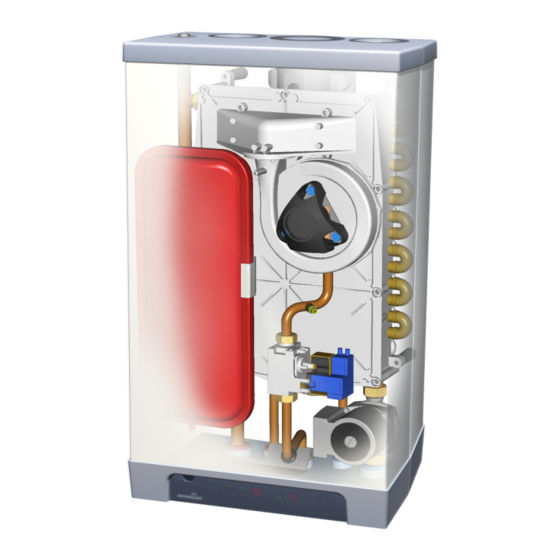
Page 12: Main Components
MAIN COMPONENTS CH pump Air supply Gas valve Flue discharge Burner controller with operating panel Connecting block / terminal list X Supply sensor S1 Condensate discharge Return sensor S2 Hot water sensor S3 Siphon Flow switch Heat exchanger Pressure gauge Operating panel and display 1m connecting cable 230 V ~ Ionisation/ignition probe... -
Page 13: Accessories
Accessories Description Pipe mounting bracket Connection supply and return 22 mm diameter • Connection cold and hot water 15 mm diameter • Connection gas ½" female thread • Mounting strip boiler • Bag with fixings • Mounting frame for top pipe connection Pipework cover Outside sensor Conversion set to Propane (LPG or G31) -
Page 14: Installation
INSTALLATION Overall dimensions CH flow 22 mm diameter 710mm InterCombi HE 32 CH return 22 mm diameter 15 mm diameter 810mm InterCombi HE 32 Cold water 15 mm diameter Domestic hot water 15 mm diameter Flue gas outlet 80 mm diameter... -
Page 15: Unpacking The Appliance
Unpacking the appliance 1. Unpack the appliance. 2. Check the content of the packaging. This consists of:- • Appliance (A) • Mounting strip (B) • Siphon (C) • T-piece & ½" Pressure relief safety valve, 3 bar • Installation instructions •... -
Page 16: Boiler Location
Boiler location The appliance can be fitted to a mounting frame. The assembly or just the appliance should be mounted to a wall with sufficient bearing strength. In case of light wall constructions, resonance sounds may occur. There must be an earthed electrical supply within a distance of 1 m from the appliance. -
Page 17: Mounting
Mounting Depending on the mounting option ordered, the following mounting methods are available:- Mounting strip (A) alone, OR mounting strip (A) and optional pipe mounting bracket (B), OR top connecting frame (C) and pipe mounting bracket (B), which are both optional items. This arrangement allows for vertical pipes from above at the rear. -
Page 18: Mount The Appliance
Mount the appliance 1. Check whether the clamping rings are straight in the couplings. 2. Place the appliance: slide it top-down over the mounting strip. Make sure that the pipes simultaneously slide into the clamp fittings. 3. The flexible tube from the condensate siphon should be inserted into an open waste pipe of not less than 32 mm diameter. -
Page 19: Connections
The appliance is fitted with a 6 litre expansion vessel which is adequate for a system with a water volume not exceeding 100 litres, typically 8 radiators. For larger volume systems, an additional expansion vessel must be fitted. Contact Atmos for advice in these cases. 5.1.2 Thermostatic radiator valves Building regulations require a room thermostat to be fitted on all installations. -
Page 20: Underfloor Heating
5.1.4 Underfloor heating For a good operation of the domestic hot water supply, there must be no undesired circulation through the appliance caused by a second pump of the CH circuit. Connect underfloor heating with an electric shut-off valve (two-way valve) to prevent circulation through the appliance when there is no demand for central heating. -
Page 21: Hot Water System
For this, the cold water connection at the bottom of the appliance must be L/min disconnected. (Not applicable) InterCombi HE32 Water pipe pressure in bar Water flow rate in l/minute ± 10% 5.2.1 Appliance with pre-heating by solar system A connecting set for appliances with the NZ label "Suitable for pre-... -
Page 22: Connecting The Gas Supply
Connecting the gas supply 1. Install a gas filter in the connection of the appliance when the gas can be polluted. 2. Connect the appliance gas valve to the gas pipe. 3. Check the boiler's data plate to ensure that the appliance has been set for the correct gas supply. -
Page 23: Room Thermostat On/Off
5.4.2 Room thermostat on/off 1. Connect the room thermostat. See § 5.4.1. 2. The terminal block for the connection for a volt free room thermostat, or time clock, is X4 on the control panel. The terminals are wired to the input circuit of the control unit, which has its own 24V dc ‘wetting voltage’... -
Page 24: Flue Discharge And Air Supply
Flue discharge and air supply Two different flue systems are available from Atmos for use with this appliance:- • 80mm twin pipe system which enables separate air intake and flue pipes to be fitted to the appliance. • 80/125mm concentric system. -
Page 25: Flue Terminal Clearances
5.5.4 Flue terminal clearances The flue terminal must be sited with minimum clearance distances as shown in the diagram. A terminal guard must be fitted if the terminal is sited less than 2m above ground level. Where the flue terminates within 1m of a plastic or painted gutter or within 500mm of painted eaves, then protection should be provided in the form of an aluminium shield at... -
Page 26: Pipe Lengths
Elbow at 90° R/D=0.5 Elbow at 45° R/D=0.5 Note – The type supplied by Atmos are Elbows. For smaller twin pipe diameters, the maximum pipe length is reduced as follows:- 70mm dia: 0.59 x max. pipe length for 80mm dia. -
Page 27: Outlet Arrangements
5.6.4 Outlet arrangements Appliance Materials Supplier category Terminal Atmos Other parts Terminal Terminal of Prefabricated chimney Other parts All materials At the CLV system Inlet grid Other parts and discharge cover All materials and terminal Inlet grid Main duct Other parts 5.6.5... -
Page 28: Outside Wall Outlet For Twin Pipe Terminal - Horizontal
Pipes for connecting the air supply and the flue discharge between the appliance and the terminal must have a diameter of 80 mm. A. Atmos twin pipe terminal horizontal. To be extended for a balcony outlet with one or two standard pipes (diameter 80 mm). B. Outlet grid. - Page 29 Mounting a twin pipe terminal extension pipe(s) for balcony outlet When the free outlet is hindered by an eave, balcony, gallery or anything else, the air supply pipe and the flue discharge pipe must be extended to at least the front side of the overhanging part. When the air supply is not disturbed by obstacles, such as a console or separating wall, and when the outlet is not at the edge of a building, the air supply pipe does not need extension.
-
Page 30: Outside Wall And Roof Outlet Concentric Terminal Horizontal
Pipes for connecting the air supply and the flue discharge between the appliance and the terminal must have a diameter of 80 mm. A. Atmos concentric terminal horizontal. For outside wall or roof outlet horizontal. B. Atmos concentric pipe. For extension of a balcony/gallery outlet. -
Page 31: Roof Outlet Combination And Twin Pipe Terminal - Vertical
Roof outlet combination and twin pipe terminal - vertical. Appliance category: C33 CAUTION When the Atmos combination terminal - vertical cannot be applied, the air supply and the flue discharge must be separated. Atmos combination terminal - vertical. - Page 32 Maximum pipe length See §5.6. Flue discharge pipe and air supply pipe For mounting, see § 5.6.5. Mounting of combination terminal - vertical 1. Mount a vertical terminal roof pile with lead flashing at the place of the outlet on a pitched roof. On a flat roof an adhesive plate for a pipe of diameter 126 mm must be applied.
- Page 33 Mounting of twin pipe terminal - vertical CAUTION The outlets of the flue discharge and air supply should be placed in the same pressure area. The air supply from the pitched roof area and the flue discharge by means of a constructional chimney is also possible, but not the other way around.
-
Page 34: Roof Outlet Prefabricated Chimney
5.10 Roof outlet prefabricated chimney Appliance category: C33 When there is little space in a shaft, a roof outlet through a prefabricated chimney may be necessary. The prefabricated chimney must comply with the minimum lengths shown. The supplier must guarantee the proper operation of the prefabricated chimney with respect to wind attack, ice formation, rain ingress, etc. -
Page 35: Roof Outlet And Air Supply From The Outside Wall
1. Make an opening of diameter 90 mm at the place of the supply. 2. Shorten the air supply pipe to the correct length out of the wall. 3. Mount the Atmos inlet grid and attach this to the pipe. 4. Slide the air supply pipe into the opening and cover the opening with a rosette, if necessary. -
Page 36: Air Supply From The Outside Wall And A Roof Outlet With Common Discharge System
CAUTION The air supply (A) in the outside wall must be provided with an Atmos inlet grid. The flue discharge (B) must be provided with a pulling discharge cover. The minimum bore of the common discharge system... -
Page 37: Roof Outlet Clv System
Remark The common discharge system has been inspected in combination with the appliance. 5.13 Roof outlet CLV system Appliance category: C43 CAUTION A roof outlet through a Combination Air supply-Flue discharge system (CLV system) is allowed. For the common flue discharge cover and air supply cover a certificate of incorporation from the Gastec-Gasinstituut is required. -
Page 38: Commissioning
COMMISSIONING Fill and de-aerate the appliance and the system WARNING Connect the appliance to the mains voltage only after filling and de-aerating! 6.1.1 CH system WARNING When an additive is added to the CH water, this should be suitable for the materials used in the appliance, such as copper, brass, stainless steel, steel, plastic and rubber. -
Page 39: Commissioning Of The Appliance
Commissioning of the appliance After having carried out the above operations, the appliance can be commissioned. 1. Switch on the electrical supply to the appliance. The appliance will carry out a self-test: 2 (on service display). After completing the self-test, the appliance goes to standby: - (on service display). -
Page 40: System Shutdown
System Shutdown CAUTION Drain the appliance and the system when the mains voltage has been disconnected and there is a chance of freezing. 1. Drain the appliance using the filling/drain tap. 2. Drain the system at the lowest point. 3. Close the main valve for the cold water supply to the boiler. 4. -
Page 41: Setting And Adjustment
SETTING AND ADJUSTMENT The functioning of the appliance is mainly determined by the (parameter) setting in the burner controller. A part of this can be set directly via the operating panel, while another part requires an Installer code to be entered before settings can be changed. -
Page 42: Parameters
Remark - This can only be done if the service code has been set. Parameters Parameter Setting Factory Description setting InterCombi HE 32 Service code [15] Access to installer settings. The service code must be entered (=15). System type 0 = standard... -
Page 43: Setting Maximum Ch Power
See table: Setting CH power. This table gives the relation between the fan speed and the appliance power. Setting CH power Required CH power Setting on service display InterCombi HE 32 (approxt kW) (% of the maximum speed) 26.2 22.7 19.7 16.7... -
Page 44: Weather-Dependent Control
T supply °C Weather-dependent control When the outside sensor is connected, the supply temperature is automatically controlled dependent on the outside temperature in accordance with the set control line. The T set CH (= CH supply temperature) is set via the temperature display. -
Page 45: Setting Gas-Air Control
another gas type, the control must be checked and reset if necessary according to the table below:- Gas type Natural gas H Propane P Gas category 2E/H G20 3P G31 (propane) 20 mBar 29 mBar % at low position (L) 8.8 –... - Page 46 Setting the gas valve by pressure measurement This method is less accurate, but usually gives a sufficient result. 1. Switch off the appliance using the on/off key (- on service display). 2. Remove the front cover of the appliance. 3. Turn the measuring nipple (C) on the gas valve open with two turns and connect this through a tube to the plus connection of the pressure gauge.
-
Page 47: Faults
FAULTS When the service display or the operating panel is flashing, the burner controller has detected a fault. In case of several faults, the temperature display shows an additional code. After the fault has been remedied, the burner controller can be restarted by pressing the reset button on the operating panel. -
Page 48: Burner Does Not Ignite
Burner does not ignite Possible causes Remedie s Gas ta p is closed. 1. Open the gas tap. Air in th e gas pipe. 1. De-aerate the gas pipe. Inlet pressure too low. 1. Contact the gas company. No ignit ion. 1. -
Page 49: Burner Resonates
Burner resonates Possible causes Remedies Inlet pressure too low. 1. The house gas meter may be faulty. Contact the gas company. Re-circulation of the flue gases. 1. Check the flue gases and air supply. Gas-air mixture not adjusted properly. 1. Check the adjustment, see Gas-air control. -
Page 50: Reduced Output
Reduced output Possible causes Remedies At high speed, the power has decreased 1. Check appliance and flue system by not more than 5%. for pollution. 2. Clean appliance and flue system. CH does not reach the correct temperature Possible causes Remedies Room thermostat settings not correct. -
Page 51: Hot Water Does Not Reach The Correct Temperature
Hot water does not reach the correct temperature Possible causes Remedies Tap flow higher than 9 l/min. 1. Adjust the inlet combination. Temperature setting water circuit too low. 1. Set the hot water circuit to 60ºC, dependent on the required temperature. No heat transfer due to scaling or pollution 1. -
Page 52: Servicing The Boiler
SERVICING THE BOILER The appliance and the system should be checked by a qualified registered person and cleaned if necessary . 1. Switch off the appliance using the on/off key on the operating panel. 2. Switch off the electrical supply to the appliance. 3. -
Page 53: Technical Specifications
B13; B33; C13; C 33; C 43; C53; C63; C83 Gas inlet pressure 20 mbar Suitable for gas Technical data InterCombi HE 32 Domestic hot water Nom. load upper value 8.0 – 36.3 Nom. load lower value 7.2 – 32.7 Nom. -
Page 54: Electrical Diagram
10.1 Electrical diagram Note F1: 5x20mm anti-surge fuse 2A. -
Page 55: Ce Declaration
CE DECLARATION Declaration of conformity according to ISO IEC GUIDE 22. Meets the stipulations of the following directives: • Machine directive (89/392/EC) as amended in directive (93/68/EC) • Low voltage directive (73/23/EC) as amended in directive (93/68/EC) • Directive concerning gas appliances (90/396/EEG) •...
Need help?
Do you have a question about the InterCombi and is the answer not in the manual?
Questions and answers