Atmos InterOpen HE22 Installation & Servicing Instructions Manual
Interopen wall-mounted gas boiler
Hide thumbs
Also See for InterOpen HE22:
- User operating instructions (4 pages) ,
- User operating instructions (2 pages) ,
- Installation instructions manual (52 pages)
Table of Contents
Advertisement
Quick Links
Advertisement
Table of Contents

Related Manuals for Atmos InterOpen HE22


Summary of Contents for Atmos InterOpen HE22
- Page 1 Atmos InterOpen Installation & Servicing Instructions for HE22 (GC 41-249-06) Atmos Heating Systems West March Daventry Northants, NN11 4SA Tel: 01327 871990 Fax: 01327 871905 e-mail: sales@atmos.uk.com internet: www.atmos.uk.com Issue 22.01.10 (Main revision)
- Page 2 Competent Persons Self Certification Scheme as an option to notifying the Local Authority directly. Similar arrangements apply in Scotland and Northern Ireland. Atmos Heating Systems is a member of the Benchmark Scheme and the Benchmark Checklist is included at the back of these Instructions. The Benchmark Checklist provides a Commissioning Checklist and Service Record to be completed by the Installer/ Service Engineer.
-
Page 3: Table Of Contents
General Flue Requirements ............................22 Flue discharge and air supply ...........................23 Roof outlet prefabricated chimney..........................29 Atmos MS System..............................30 Atmos Communal Flue System (CFS) ........................31 6. Commissioning Fill and de-aerate the appliance and the system.......................32 Commissioning of the appliance ..........................33 System Shutdown ..............................34 7. - Page 4 9. SERVICING THE BOILER AND COMPONENT REPLACEMENT SERVICING THE BOILER ............................45 COMPONENT REPLACEMENT..........................46 10. Technical Specifications 10.1 Electrical diagram..............................49 11. CE Declaration NOTE The Benchmark Checklist & Service Record are included at the back of the Manual.
- Page 5 This manual Using this manual you can safely install and maintain this appliance. Carefully follow the instructions. In case of doubt, contact Atmos Heating Systems. Keep these instructions near the appliance. Abbreviations and names used Description To be referred to as...
- Page 6 Exceptions 7. In the event of full payment for a product not being received, Atmos shall be discharged from all further contractual or warranty obligations. 8. Surface and/or transport damage are outside the scope of this warranty.
-
Page 7: Safety Regulations
(Installation and Use) Regulations; October 1994. Failure to install appliances correctly could lead to prosecution. Atmos Heating Systems does not accept any liability for damage or injury caused by not (strictly) observing the current safety regulations and instructions, nor by negligence while installing the Atmos InterSystem wall-mounted gas heater and any accompanying accessories. -
Page 8: Description Of The Appliance
DESCRIPTION OF THE APPLIANCE General The Atmos InterOpen wall-mounted gas boiler is suitable for open vent systems with a header tank. The appliance is designed for delivering heat to the water of a CH system and heating hot water via an indirect hot water tank. - Page 9 0 Pump overrun Note Pump overrun is only available if the After the operation of the CH, the pump has an overrun. This overrun pump output is used (terminal X2/8) time is set to the value according to parameter 8 (see § 7.3; factory –...
-
Page 10: Pc Interface
PC interface The controller has an interface for a PC. With a special cable and accompanying software, a PC can be connected. This provision makes it possible to follow the behaviour of the controller, the appliance and the heating system during a long period. Test programmes In the controller, there is provision for putting the appliance into a test status. -
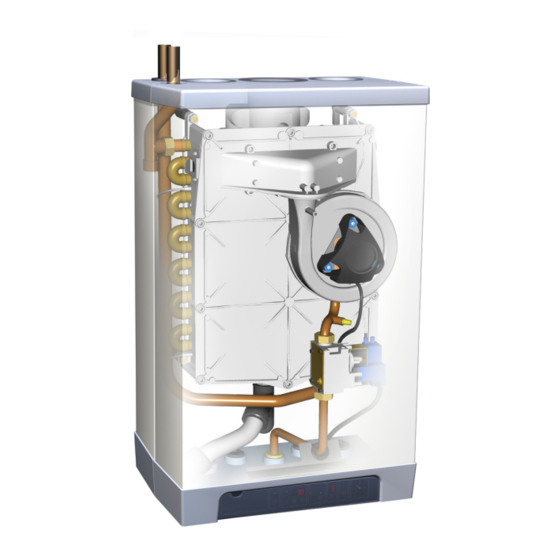
Page 11: Main Components
MAIN COMPONENTS Gas valve Flue discharge (or concentric connection) Clamping plate Connecting block / terminal list X Supply sensor S1 Condensate discharge Return sensor S2 Condensate trap Heat exchanger 1m connecting cable 230 V ~ Controller operating panel and display Sight glass and mirror Ionisation/ignition probe Air supply (left or right) -
Page 12: Accessories
Accessories Description Part Ref Rear mounting frame for top pipe connection 092507 Bottom Pipework cover 092527 Conversion set to Propane (LPG or G31) 075537 Interface cable (for Installers) 230677... -
Page 13: Installation
INSTALLATION Overall dimensions CH flow 22 mm diameter 610mm InterOpen HE 22 CH return 22 mm diameter 750mm InterOpen HE 22 15 mm diameter Flue gas outlet 80 mm diameter Condensate 32 mm dia (after trap 25 mm dia flexib ) le Air supply inlet 80 mm diameter... -
Page 14: Unpacking The Appliance
Unpacking the appliance 1. Unpack the appliance. 2. Check the content of the packaging. This consists of:- • Appliance (A) • Mounting strip (B) • Condensate trap (C) • Installation Instructions • User Operating Instructions • Warranty card 3. Valve set (supplied separately with boiler) comprising 2 x 22mm isolation valves, 1 x gas valve. -
Page 15: Boiler Location
Boiler location Clearances Above casing 200mm min Below casing 230mm min 30mm min 30mm min Front 30mm min (in operation) Front 450mm min (servicing) Keep 50 mm free space above the front panel in order to be able to remove the front panel from the casing. The appliance can be fitted to a mounting frame. -
Page 16: Mounting
Mounting Depending on the mounting option ordered, the following mounting methods are available:- Mounting strip (A) alone, OR rear mounting frame (C), which is an optional item. This arrangement allows for vertical pipework behind the boiler. Note that for this appliance, the CH flow and CH return are at the top of the casing. -
Page 17: Mount The Appliance
Mount the appliance 1. Place the appliance: slide it top-down over the mounting strip. 2. The flexible tube from the condensate trap should be inserted into an open waste pipe of not less than 32 mm diameter. If connected to a soil pipe or waste system, the waste pipe must include a trap (similar to arrangement for washing machine). -
Page 18: Condensate Disposal
Condensate disposal The appliance is provided with a 25 mm flexible pipe from its condensate trap. As given in §4.6, this should be inserted into an open waste pipe of not less than 32 mm diameter, together with the safety discharge pipe. -
Page 19: Connections
CONNECTIONS Connect the CH system 1. Flush the CH system thoroughly. 2. Connect the flow and return pipes to the top pipes from the appliance. All pipes must be mounted tension-free in order to avoid ticking of the pipes. Existing connections must not be twisted in order to avoid leaks at the connections with the external pipes. -
Page 20: Electrical Connection
Electrical connection CAUTION The appliance requires a 230 V ac 50 Hz mains supply, and must be earthed and connected via a double pole isolating switch fitted with a 3 amp fuse. The switch must be readily accessible, within 1m of the appliance, and provide complete electrical isolation for the boiler and control system. - Page 21 5.3.1 24V dc Electrical connections 24V dc Terminals X4 Description Connector X4 Remarks Room stat 6 - 7 6= +24Vdc Frost stat 6 -7 Parallel through room stat Power 24Vdc 6= +24Vdc, 9= -. (3VA) Notes 1. Under no circumstances must any electrical power be input to the room thermostat terminals.
-
Page 22: General Flue Requirements
General Flue Requirements 5.4.1 Flue terminal clearances The flue terminal must be sited with minimum clearance distances as shown in the diagram. A terminal guard must be fitted if the terminal is sited less than 2m above ground level, or above a balcony, or accessible flat roof. -
Page 23: Flue Discharge And Air Supply
We recommend that the guidance given in this document is adhered to, especially in the case of twin pipe flue systems. Flue discharge and air supply A number of different flue systems are available from Atmos for use with this appliance:- •... - Page 24 5.5.2 60/100mm Concentric extended flue system Refer to the Atmos Price List for the full list of flue components. Table of Atmos 60/100mm concentric flue equivalent lengths Maximum equivalent concentric length allowed is 10 metres (Note: Includes an allowance for the terminal;...
- Page 25 6. In its place, fit the sealing ring ø 116 x 110 mm (item B in photo). 7. Fit the adapter (item A in photo) on the flue discharge. 5.5.4 80/125mm Concentric flue system Refer to the Atmos Price List for the full list of flue components.
- Page 26 (see diagram). Table of Atmos 80/125mm concentric flue equivalent lengths Maximum equivalent concentric length allowed is 27 metres (Note: Includes an allowance for the terminal; ie the terminal can be ignored from the equivalent length)
- Page 27 5.5.6 80mm twin pipe flue system Refer to the Atmos Price List for the full list of flue components. Terminal The flue discharge at the terminal must be at least 75mm in front of the air intake and the distance between the two pipes at least 75mm.
- Page 28 This is to prevent excessive corrosion. Atmos can supply a condensate drain-off fitting for 80mm flue pipe. It incorporates a flue test point and it needs to be fitted into a vertical section of the flue.
-
Page 29: Roof Outlet Prefabricated Chimney
Roof outlet prefabricated chimney Appliance category: C33 When there is little space in a shaft, a roof outlet through a prefabricated chimney may be necessary. The prefabricated chimney must comply with the minimum lengths shown. The supplier must guarantee the proper operation of the prefabricated chimney with respect to wind attack, ice formation, rain ingress, etc. -
Page 30: Atmos Ms System
1. Make an opening of diameter 90 mm at the place of the supply. 2. Shorten the air supply pipe to the correct length out of the wall. 3. Mount the Atmos inlet grid and attach this to the pipe. 4. Slide the air supply pipe into the opening and cover the opening with a rosette, if necessary. -
Page 31: Atmos Communal Flue System (Cfs)
Atmos Communal Flue System (CFS) A design service is provided for each application. There are different configurations possible and the main ones are illustrated. CFS-NV Naturally ventilated, working under negative pressure CFS-FA Fan assisted, working under positive pressure – smaller diameter pipes are used 5.8.1... -
Page 32: Commissioning
COMMISSIONING Note The appliance must be installed and Fill and de-aerate the appliance and the system commissioned in accordance with the manufacturer’s instructions in order to comply WARNING with the Building Regs. To demonstrate compliance, the Benchmark Checklist Connect the appliance to the mains voltage only after (located at the back of this Manual) should be filling and de-aerating! completed and signed at the time of... -
Page 33: Commissioning Of The Appliance
The appliance may carry out a self-test as determined by the controller: for ‘hw’ and ‘pressure’ are 2 (on service display). not applicable for the HE22 appliance. After completing the self-test, a horizontal mark will appear in the service display: - . -
Page 34: System Shutdown
System Shutdown CAUTION Drain the appliance and the system when the mains voltage has been disconnected and there is a chance of freezing. 1. Drain the appliance using the drain valve. 18. Drain the system at the lowest point. 6.3.1 Frost protection •... -
Page 35: Setting And Adjustment
SETTING AND ADJUSTMENT The functioning of the appliance is mainly determined by the (parameter) setting in the appliance controller. A part of this can be set directly via the operating panel, while another part requires an Installer code to be entered before settings can be changed. -
Page 36: Parameters
Parameters Parameter Setting Factory Description setting InterOpen HE 22 Service code [15] Access to installer settings. The service code must be entered (=15). System type 0 = standard 1 = heating only operation + indirect hot water tank (Note: Factory setting is 1. Do not change this setting) 2 = n/a 3 = n/a CH pump continuous... -
Page 37: Setting Maximum Ch Power
See table: Setting CH power. This table gives the relation between the fan speed and the appliance power. Setting CH power Required CH power Setting on service display InterOpen HE22 (approx kW) (% of the maximum speed) 22.6 20.5 19.1 17.8... -
Page 38: Conversion To Other Gas Type
Conversion to other gas type CAUTION Activities on the gas-containing parts should only be executed by a qualified registered installer. When the appliance is connected to another gas type than the type for which the manufacturer has set the appliance, the gas setting ring must be replaced. -
Page 39: Setting Gas-Air Control
Gas type Natural gas H Propane P Gas category 2H G20 3P G31 (propane) % at low position (L) 8.8 – 9.2 9.3 – 9.7 (service and -) % at high position (H) 8.6 – 9.6 9.5 – 10.5 (service and +) Gas inlet pressure dynamic (mBar) 17-25 25-45... -
Page 40: Carbon Monoxide : Carbon Dioxide Ratio
Caution: Check the measuring nipples used for gas tightness. Carbon monoxide : carbon dioxide ratio Atmos recommends that a carbon dioxide : carbon monoxide ratio test is carried out when the boiler is commissioned. This is best done when the CO content of the flue gasses is measured. -
Page 41: Faults
FAULTS When the controller detects a fault, the red fault LED flashes (above the Reset button) and a fault code is shown on the Temperature display. After the fault has been remedied, the controller can be restarted by pressing the Reset button for 5 secs. The following faults are detected and displayed:- Temperature Description... -
Page 42: Burner Does Not Ignite
Burner does not ignite Possible causes Remedies Gas tap is closed 1. Open the gas tap. Air in th e gas pipe. 1. De-aerate the gas pipe. Inlet pressure too low. 1. Contact the gas company. No ignition 1. Replace the ignition probe. No spark. -
Page 43: Burner Resonates
Burner resonates Possible causes Remedies Inlet pressure too low. 1. The house gas meter may be faulty. Contact the gas company. Re-circulation of the flue gases. 1. Check the flue gases and air supply. Gas-air mixture not adjusted properly. 1. Check the adjustment, see Gas-air control. -
Page 44: Reduced Output
Reduced output Possible causes Remedies At high speed, the power has decreased 1. Check appliance and flue system by not more than 5%. for pollution. 2. Clean appliance and flue system. CH does not reach the correct temperature Possible causes Remedies Room thermostat settings not correct. -
Page 45: Servicing The Boiler And Component Replacement
SERVICING THE BOILER AND COMPONENT REPLACEMENT SERVICING THE BOILER The appliance and the system should be serviced annually by a qualified service engineer . For appliances connected to propane gas, a six monthly service in the first two years to simply clean the condensate trap and pipe may be neccessary. -
Page 46: Component Replacement
2 posidrive screws as shown in diagram §5.3. 9.2.2 Gas valve/ ignition block Note: The gas valve is factory-preset and therefore only Atmos or their agents can supply these. Remove the spark ignition block by pulling apart horizontally. Undo the upper and lower unions, making sure that the ‘O’... - Page 47 9.2.3 Remove the electrical connector. Undo the upper union from the gas valve. Undo the two 8mm nuts as shown in the photo. Remove the assembly including the sealing ring. Undo the three Allen screws (M4x10) to remove the gas inlet sub assembly. Fit the replacement fan in reverse order.
-
Page 48: Technical Specifications
TECHNICAL SPECIFICATIONS Appliance category B13; B33; C13; C 33; C 43; C53; C63; C83 Gas inlet pressure 20 mbar Suitable for gas Technical data InterOpen HE 22 Heat power input (gross)* 7.0 – 26.3 Heat power input (net)* 6.3 – 23.7 Heat output at 80/60°C* 6.1 –... -
Page 49: Electrical Diagram
10.1 Electrical diagram Notes 1. F1: 5x20mm anti-surge fuse, 2A. 2. 230Vac stat circuit: Available for room stat, etc. The switched live can also be used for S plan or Y plan circuits (note that the 230Vac live to the Wiring Centre must come from the same fused spur as the 230Vac supply to the boiler). -
Page 50: Ce Declaration
Manufacturer: Atmos Heating Systems Address: West March, DAVENTRY, Northants, NN11 4SA Hereby declares that the application: Atmos, Type InterOpen HE22 Meets the stipulations of the following directives: • Machine directive (89/392/EC) as amended in directive (93/68/EC) • Low voltage directive (73/23/EC) as amended in directive (93/68/EC) •...
Need help?
Do you have a question about the InterOpen HE22 and is the answer not in the manual?
Questions and answers