Table of Contents

Related Manuals for Atmos Multi Series


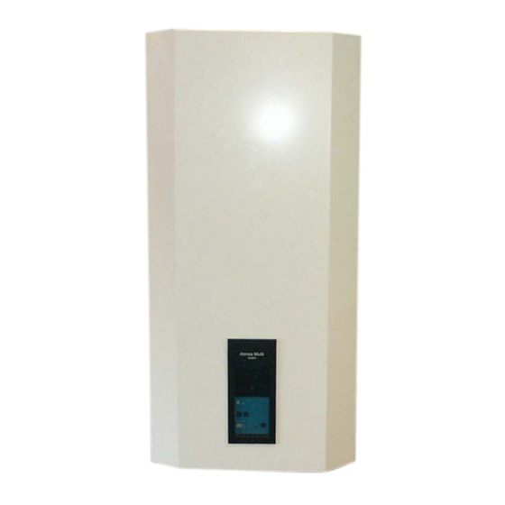
Summary of Contents for Atmos Multi Series
- Page 1 Atmos Multi ATMOS ATMOS Installation & Servicing Instructions Atmos Heating Systems West March Daventry Northants, NN11 4SA Tel: 01327 871990 Fax: 01327 871905 e-mail: sales@atmos.uk.com internet: www.atmos.uk.com MK2 Revised (M) 2.7.04...
-
Page 3: Table Of Contents
7.7 Connecting the mains water 7.8 Wall Frame Assembly 7.9 Connecting the domestic hot water supply 7.10 Hot water secondary circulation. 7.11 Connecting the gas supply 7.12 Connecting the condensate siphon 7.13 Connecting the electrical supply Page 3 ATMOS MULTI Mk 2 version 2004... -
Page 4: Introduction
Introduction The Atmos Multi must be installed in accordance The Atmos Multi gas fired storage combination with these instructions and the regulations boiler meets the requirements of Statutory currently in force. Please read these instructions Instrument 'The Boiler (Efficiency) Regulations'... -
Page 5: Installation Regulations
1. Installation Regulations. 2. General Information. 1.1 The appliance must be installed by a qualified 2.1 The Atmos Multi is a wall mounted, fully registered installer in accordance with the Gas Safety automatic gas fired condensing combination boiler (Installation and Use) Regulations; October 1994. -
Page 6: Technical Data
Underfloor heating flow connection ½" BSPF DIMENSIONS AND WEIGHT Height 1090 mm Width 530 mm Depth 507 mm Dimensions of Multi Weight empty (full) 70 kg (150kg) with wall mounting frame Protection Class IP44 Page 6 ATMOS MULTI Mk 2 version 2004... -
Page 7: Schematic Of Boiler
4. Schematic of Atmos Multi Boiler Page 7 ATMOS MULTI Mk 2 version 2004... - Page 8 OUTLET CASTING ATMOS CONTROL UNIT ATMOS HEAT EXCHANGER FOR EXTRA HOT WATER ATMOS (only for 24/80 Plus & 32/80 Plus) TEMP. & PRESSURE RELIEF VALVE ½” x 15 mm, 7 bar 93 FLUE GAS OUTLET CONNECTION Ø 80 mm AIR SUPPLY CONNECTION Ø...
-
Page 9: Operation And Construction
5. Operation and Construction The Atmos Multi is a fully automatic, gas fired, high efficiency central heating boiler providing unvented domestic hot water at mains pressure via an integral 80 litre copper hot water storage tank. 5.1 Appliance construction A heat exchanger consisting of three concentric channels is positioned in the centre of the boiler's integral hot water tank. -
Page 10: Operating Principle
If no flame signal is Weather-dependent control detected after 5 seconds, two more attempts for Using an extra kit available from Atmos, burner ignition will be made within a 15-second comprising an external temperature sensor and a period, after which the appliance will shut down. -
Page 11: Controls And Function
Section 12 of these instructions activities. To protect against accidental use, the set button has to be depressed for a period of 5 seconds before activation occurs. (See 'User's program'). Page 11 ATMOS MULTI Mk 2 version 2004... -
Page 12: User's Program
3amp. parameter appears in the central heating water display window. Pressing the 'Hot water' The Atmos Multi is supplied factory wired button enables the setting to be changed to the complete with 1·2m of mains cable. All electrical required value. -
Page 13: Flue Terminal Clearances
Depending upon the boiler location and flue configuration required, accordance with BS5440:1. two different flue systems are available for use with the Atmos Multi Horizontal flue pipe runs must always boiler: be installed with a minimum slope of 5mm/metre towards the boiler. This... - Page 14 Figure 5: Twin pipe terminal plate The twin pipe horizontal wall terminal comprises a terminal plate, two 500mm lengths of 80mm dia. plastic pipe and internal plate. In addition, two 90º bends are required Page 14 ATMOS MULTI Mk 2 version 2004...
-
Page 15: Condensate Disposal
Where the Atmos Multi is installed in a property where discharge from the unit may not be apparent, While a minimum 300mm of vertical discharge pipe... - Page 16 Subtract the resistance for 4 No. 22mm elbows at .8m each =3.2m Therefore the maximum permitted length equates t o 5.8m, which is less than the actual length of 7m. Therefore calculate the next largest size (28mm ) . ATMOS MULTI Mk 2 version 2004 Page 16...
-
Page 17: Existing Systems
Red expansion vessel including wall bracket and safety valve. Using a knife, cut open the bottom tray of the box and remove the top box from the bottom tray (Fig. ATMOS MULTI Mk 2 version 2004 Page 17... -
Page 18: Minimum Clearances
(fig. 10 & fig 11) Figure 10: Dimensions & minimum clearances 7.3 Boiler location. The Atmos Multi is not suitable for external installation. While the appliance itself is provided with integral frost protection, it must be installed in a room that stays free of frost. -
Page 19: Wall Mounting The Boiler
Alternatively, a special position the corners of the back of the casing mounting frame is available from Atmos as an level with each end of the mounting bracket. optional item. -
Page 20: Connecting The Flue System
It is recommended that a 85mm diameter core drill is used for cutting through the external wall. For concentric and vertical roof systems, refer to separate installation instructions supplied with the flue assemblies. Page 20 ATMOS MULTI Mk 2 version 2004... -
Page 21: Connecting The Central Heating Circuit
(Fig 14). The flow eriod. pipe (A) is colour coded red and the return pipe (B) Connection of the Atmos Multi to a heating system is colour coded blue. containing non-diffusion barrier oxygen permeable plastic pipe or class 'H' plastic pipe will invalidate Figure 14: Boiler flow &... -
Page 22: Connecting The Mains Water
(Connection O in Each Atmos Multi boiler is supplied with a mains Fig 11). This allows for the separate heating of a pressure kit comprising the following components: radiator when the boiler is operating in either central heating or hot water mode. -
Page 23: Wall Frame Assembly
½” bsp to the boiler gas inlet with suitable gas sealant. There is no valve on the valve plate, so connect the gas pipe directly to the incoming 22mm gas pipe through the hole provided. ATMOS MULTI Mk 2 version 2004 Page 23... - Page 24 Mixed) to the domestic hot water supply. can be done. Supply size can be 15mm or 22mm, depending on the load, but 22mm will be required for more than one bathroom. ATMOS MULTI Mk 2 version 2004 Page 24...
- Page 25 15mm compression straight connector. Connect to the heating system safety valve discharge. The black tundish should be pointing down, and the open part facing forward for clear visibility. ATMOS MULTI Mk 2 version 2004 Page 25...
- Page 26 UK 32mm pipe) The outlet must be protected. 13. Finally Tighten all joints, check over, fill system with water, and test for water tightness. Test for gas tightness. ATMOS MULTI Mk 2 version 2004 Page 26...
-
Page 27: Connecting The Domestic Hot Water Supply
UV4 manifold. If the secondary return loop has a volume in excess of 1 litre, a larger potable expansion vessel should be used. Contact Atmos Heating Systems for further advice. A non-return valve must be fitted to the return loop... -
Page 28: Connecting The Condensate Siphon
A wiring diagram of the Atmos Multi is given in All electrical connections to the mains supply must Fig 24. be made in full accordance with the current I.E.E. -
Page 29: Atmos Multi Mk 2 Version
Figure 24: Atmos Multi wiring diagram . WARNING! 230 VOLTS AC = BLUE Y/GR = YELLOW/GREEN = RED = BROWN = GREY = WHITE = YELLOW = ORANGE = BLACK ATMOS MULTI Mk 2 version 2004 Page 29... -
Page 30: Commissioning
8.1 Filling the heating system. Warning! The Atmos Multi must not be operated without filling with water. On completion of the boiler installation and ensuring that all water connections are correctly... -
Page 31: Filling The Domestic Hot Water System
Section 12.). If this report is shown, the appliance button twice to change to 75ºC. Press the ‘Reset’ will only run at its minimum capacity. Correct the button twice to exit the program. pressure before proceeding. ATMOS MULTI Mk 2 version 2004 Page 31... -
Page 32: System Balancing
The required water flow rate through the appliance (depending on boiler model), the time taken to use is 0·8 m³/h and 1·2 m³/h for the Atmos Multi 24 and 0.024 m³ (0.847 ft³) or 0.032 m³ (1.130 ft³) of gas 32 models respectively. -
Page 33: System Shutdown
Note! On shutting down the central heating system, it is recommended not to set the room thermostat The Atmos Multi is made of a number of primary lower than 10ºC during the winter months. To materials, especially copper, aluminium and steel. - Page 34 Note! If the flue's 80mm diameter gas discharge duct is longer than 10 metres, the gas rate can be reduced. The measured time will in this case increase by up to 2%. ATMOS MULTI Mk 2 version 2004 Page 34...
-
Page 35: Auxiliary Equipment Inspection
Finally, check that there is no 3. Cleaning the heat exchanger. leakage when the valves are returned to their closed 4. Inspect air supply/flue gas discharge system. position. 5. Unvented hot water tank inspection. ATMOS MULTI Mk 2 version 2004 Page 35... - Page 36 3 fixing nuts securing the burner to the inlet casting, using an 10mm socket. (Fig 33 tems 1 and 2) Disconnect the push on electrical connections to the fan, high temperature thermostat, ignition electrode nd ionisation electrode. ATMOS MULTI Mk 2 version 2004 Page 36...
-
Page 37: Completion Of Inspection And
8mm spanner and remove gas valve action where necessary. Figure 36 5 . Unvented hot water tank inspection. Remove the hot water tank's insulation shell, ensuring it is intact and free from damage. Replace if necessary. ATMOS MULTI Mk 2 version 2004 Page 37... -
Page 38: Supply
1 & 2 and ignition out from terminals 3 & 4. order, replacing the sealing gasket. Warning! Incorrect connection to the transformer terminals will result in damage to the boiler control unit. ATMOS MULTI Mk 2 version 2004 Page 38... -
Page 39: Supply
8mm spanner (Fig 43). Fit replacement pressure sensor in reverse order. Note: Do not overtighten the connection! Fit the replacement sensor in reverse order. ATMOS MULTI Mk 2 version 2004 Page 39... -
Page 40: Supply
Fit replacement valve in reverse order using a Press button on left side of the valve head and lift sealant suitable for potable water. off (Fig 47). Fit replacement valve head in reverse order. ATMOS MULTI Mk 2 version 2004 Page 40... - Page 41 50mm above where they penetrate the boiler case. Remove hot water tank and fit replacement in reverse order, using the two 15mm compression fittings provided to reconnect the domestic hot and cold water pipes. Figure 50 ATMOS MULTI Mk 2 version 2004 Page 41...
-
Page 42: Malfunctions
12. Malfunctions. Malfunction report . A malfunction is a fault The Atmos Multi has three types of malfunctions that causes the appliance to be shut down by the that can be reported via the diagnostic display, as control unit and locked. The appliance can only be follows :- unlocked by pressing the 'Reset' button.
Need help?
Do you have a question about the Multi Series and is the answer not in the manual?
Questions and answers