Subscribe to Our Youtube Channel
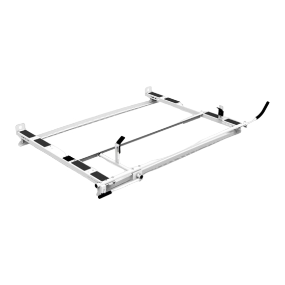
Summary of Contents for Holman 4A80L
- Page 1 Instruction Guide 4A80L Holman Rancho Cordova, CA 95742 800-343-7486 InstallationSupport@Holman.com 20210629R5 DATE: ________________...
-
Page 2: Table Of Contents
Step 8 – Mount Ladder Stop ........................15 Before You Begin • Read all instructions prior to assembling or installing any Holman product. • Find your vehicle roof rail mounting prior to rack assembly. • Be sure to put sealant around all threads entering cargo area and between the rubber spacer and roof of vehicle to prevent water from leaking into cargo area. -
Page 3: Parts List
Instructions – 4A80L Parts List For Technical Support Call: 800-343-7486 Monday-Friday 7AM - 4 PM (PST) Page 2... -
Page 4: Hardware (18-4A80L-A)
Instructions – 4A80L Hardware (18-4A80L-A) For Technical Support Call: 800-343-7486 Monday-Friday 7AM - 4 PM (PST) Page 3... -
Page 5: Hardware (18-4A80L-M)
Instructions – 4A80L Hardware (18-4A80L-M) For Technical Support Call: 800-343-7486 Monday-Friday 7AM - 4 PM (PST) Page 4... - Page 6 Instructions – 4A80L Hardware (18-4A80L-M) (Continued) For Technical Support Call: 800-343-7486 Monday-Friday 7AM - 4 PM (PST) Page 5...
-
Page 7: Promaster City Installation
Instructions – 4A80L DO NOT EXCEED MANUFACTURERS WEIGHT CAPACITY FOR ROOF ProMaster City Installation • Locate 6 mounting locations shown on roof of van. • Install mounting rail as shown using M6 x 22mm bolts with 1/4” lock washers and 1/4” flat washers. -
Page 8: Nv200/City Express Installation
Instructions – 4A80L DO NOT EXCEED MANUFACTURERS WEIGHT CAPACITY FOR ROOF NV200/City Express Installation • Locate 4 mounting locations shown on roof of van. • Install mounting rail as shown using M8 x 25mm bolts with 5/16” lock washers and 5/16” flat washers. -
Page 9: Transit Connect Installation
Instructions – 4A80L DO NOT EXCEED MANUFACTURERS WEIGHT CAPACITY FOR ROOF Transit Connect Installation • Locate 4 mounting locations shown on roof of van. • Be sure to put rubber washer between the mounting rail and the roof to ensure sealing. -
Page 10: Metris Rail Installation
Instructions – 4A80L DO NOT EXCEED MANUFACTURERS WEIGHT CAPACITY FOR ROOF Metris Rail Installation • Locate 6 mount locations on van roof, 4 rear and 2 mid-roof, as shown. • Remove plastic cap in these locations indicated to expose threads in the roof. -
Page 11: Assembly Instructions
Instructions – 4A80L Assembly Instructions Step 1 – Mount Feet to Rails • Place both bows on top of installed rails. Bolt feet to rails using 5/16” x 1” hex head, two 5/16” flat washers and a 5/16” lock nut. -
Page 12: Step 3 - Install End Stops
Instructions – 4A80L • Use a 3/8” x 3/4" hex head bolt, 3/8” lock washers and a 3/8” flat washer to bolt foot to cross member. • DO NOT TIGHTEN at this point. • Feet can be installed as shown below or reverse depending on how you mounted the rail. -
Page 13: Step 4 - Mount Side Tube
Instructions – 4A80L Step 4 – Mount Side Tube • Assemble the side tube. • Place sealant around the connection of the two tubes. • While still malleable, place the side tube assembly on top of the installed bows. Have the bend towards the front and outside of the vehicle as shown. -
Page 14: Step 5 - Assemble Clamp Mechanism
Instructions – 4A80L Step 5 – Assemble Clamp Mechanism • Place the angle bracket on top of the installed bows with the long flange towards the center of the vehicle. Do NOT install any hardware. • Insert plastic bushings into the angle bracket and the ladder stop installed in Step 4, with the large flanges of the bushings towards each other and to the inside of the brackets as shown. -
Page 15: Step 6 - Mount Handle
Instructions – 4A80L • Bolt the angle bracket to the front and rear bow using 3/8” x 1” carriage bolts, 3/8” flat washers and a 3/8” lock nuts as shown. • Be sure the bushings CANNOT come out. • TIGHTEN. -
Page 16: Step 7 - Mount Latch
Instructions – 4A80L Step 7 – Mount Latch • Bolt the latch to the round tube installed in Step 4 through the vacant slot using 5/16” x 2” carriage bolt, 5/16” flat washer and a 5/16” lock nut. • TIGHTEN. - Page 17 Instructions – 4A80L • Adjust clamps to fit firmly against the ladder. GO BACK AND ENSURE ALL HARDWARE IS TIGHT INSTALLATION IS NOW COMPLETE. For Technical Support Call: 800-343-7486 Monday-Friday 7AM - 4 PM (PST) Page 16...


Need help?
Do you have a question about the 4A80L and is the answer not in the manual?
Questions and answers