ISHIDA AC-4000 Service Manual
System scale printer
Hide thumbs
Also See for AC-4000:
- Operator's manual (37 pages) ,
- Operation & setup manual (4 pages) ,
- Service manual (7 pages)
Table of Contents
Advertisement
Quick Links
Advertisement
Table of Contents

Related Manuals for ISHIDA AC-4000


Summary of Contents for ISHIDA AC-4000
- Page 1 System Scale Printer SERVICE MANUAL IMPORTANT • Do not carry out installation, operation, service, or maintenance until thoroughly understanding the contents of this manual. • Keep this manual available at all times for installation, operation, service, and maintenance. Manual No. 0181B...
- Page 2 You can help improve this manual by calling attention to errors and by recommending improvements. Please convey your comments to the nearest Ishida Company regional representative. Thank you! Copyright 2003 by Ishida Co., Ltd. All Rights Reserved.
- Page 3 Do not perform unspecified maintenance For your personal safety, do not perform any maintenance procedures which are not specified in the manual. Disconnect power supply before servicing To ensure your personal safety, disconnect the power supply before servicing. AC-4000 Service Manual No.0181B...
- Page 4 Never use thinner or other volatile liquids. Power Supply • Use the appropirate voltage after referring to the specification plate located on the machine. • Use a dedicated power source. (Voltage fluctuation may cause the machine to malfunction) AC-4000 Service Manual No. 0181B...
- Page 5 Always ensure that the machine is level. If the machine is not level, weighing may not be accurate. Adjust the machine to a level position using the four level adjustment feet located on the buttom of the machine, until the bubble is completely centered in the round level indicator. AC-4000 Service Manual No.0181B...
-
Page 6: Table Of Contents
IBIOS PROGRAM No......................3-6 3.4 RAM Clear ........................... 3-7 ISRAM CLEAR ........................3-7 ISETUP CLEAR ......................... 3-8 ITEST DATA SET ....................... 3-8 IAPPLICATION COPY ......................3-9 IBIOS COPY ........................3-9 IBOOT COPY ........................3-10 AC-4000 Service Manual No. 0181B... - Page 7 I10 DIGIT FLAG 8/13 ....................... 4-10 IBARCODE TYPE ......................4-10 IPOS TYPE ........................4-11 IITF ..........................4-12 IMANUFACTURE CODE ....................4-12 4.6 Item Code ........................... 4-13 IBARCODE POSITION ..................... 4-13 IDEPARTMENT CODE ..................... 4-13 IGROUP CODE ........................ 4-13 AC-4000 Service Manual No. 0181B...
- Page 8 ILOGO IMAGE 2 ......................4-23 ILABEL FORMAT No......................4-23 IUPPER LIMIT ........................4-23 ILOWER LIMIT ......................... 4-24 IUNIT TYPE ........................4-24 IDEPARTMENT CODE ..................... 4-24 IGROUP CODE ........................ 4-24 IREGISTER CODE ......................4-24 ICOST PRICE ........................4-25 AC-4000 Service Manual No. 0181B...
- Page 9 5.4 PK-229 (A/D board) ......................5-8 5.5 Lithium Battery ........................5-8 5.6 Power Unit (LSF100 - 24S) ....................5-9 5.7 PK-232 (TCP/IP) ........................ 5-10 5.8 PK-236 (Span switch) ......................5-11 5.9 P-862 (Key board) ......................5-11 AC-4000 Service Manual No. 0181B...
- Page 10 IDetaching the thermal head ..................... 7-9 ICleaning the thermal head ..................... 7-10 IDetaching the display ..................... 7-10 ICleaning the cassette sensor/peel sensor ..............7-11 IAdjusting the belt tension ....................7-11 7.3 Periodical Replacement Parts ................... 7-12 AC-4000 Service Manual No. 0181B viii...
-
Page 11: Chapter 1 Overview
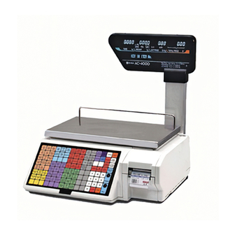
1.1 Appearance and Name of Each Part Operator display Customer display Weigh platter Fuse Printer cassette Power supply receptacle Key sheet Power switch Upper surface: Operation key sheet Lower surface: Program key sheet 1.2 Display AC-4000B AC-4000E AC-4000 Service Manual No. 0181B... -
Page 12: Printer
Chapter 1 Overview 1.3 Key Sheet 1.4 Printer Roll holder Peel shaft Roll stopper U-pin Winding bobbin AC-4000 Service Manual No. 0181B... -
Page 13: Main Specifications
3. SRAM file: Approx. 949k bytes 949k bytes for registration 9k bytes for file creation (940k bytes available after RAM is cleared) PLU, Store name/address, Extra message 1/2/3, Coupon, Preset, Label format, Field title, and Operator AC-4000 Service Manual No. 0181B... -
Page 14: Exploded Drawing
Chapter 1 Overview 1.6 Exploded Drawing Weigh platter Platter holder Top case Display Power supply Load cell Fuse Printer cassette Power switch Module RS232C Power cord PK-229 (A/D board) Operation panel (Key sheet) P-950B (Main board) AC-4000 Service Manual No. 0181B... -
Page 15: Chapter 2 Installation
Open the packing case and check whether there are all the packed goods (machine and attachments) and if there are any damaged parts. Note: AC-4000 “B type” or “E type” can be identified by a description of the sticker on the case. 1. Stand 2. -
Page 16: Installation Environment
Insert the two bosses of the stand into the main body. Tighten the stand and the main body with the Screw (A) (M4x8) 2 screw (B). Screw (A) Stand Main body Boss Screw (B) (M4x8) Connector AC-4000 Service Manual No. 0181B... -
Page 17: Weigh Platter Installation
Roll stopper Pass the label roll as shown in the figure below, Push the printer cassette to its original position. and fix the roll end with the U-pin. AC-4000 Service Manual No. 0181B... -
Page 18: Power Switch "On
Power supply 110 220 2.7 Power Switch “ON” • Turn on the power switch located at the left side of main body. Note: Push the “O” side of the switch to urn off the power. AC-4000 Service Manual No. 0181B... -
Page 19: Customer's Specification Setup (Initialization, Setup, And Registration)
6. Open price ..............P.4-17 7. PLU selection ..............P.4-18 8. System ................P.4-26 9. Ethernet setup .............. P.4-30 10. System timer ..............P.4-37 11. Password setup ............P.4-38 12.Machine number setup ..........P.4-40 AC-4000 Service Manual No. 0181B... -
Page 20: Normal Mode Display
2.9 Normal Mode Display All segments blink three times when the power is turned on. Then, the initial display appears. IOperator display ICustomer display When calling up “Fixed price item” or “Weighing item”. IWeighing item IFixed price item AC-4000 Service Manual No. 0181B... -
Page 21: Label Batch Print Mode
The registered data is preserved as it is if there are any registered items. Printing preserved data If there is any preserved print data, printing starts by pressing the PRINT key. Note: An error buzzer sounds if there is no registered data. AC-4000 Service Manual No. 0181B... -
Page 22: Label Batch Printing On Continuous Paper
(When there are “40 preserved items”, “59 items” can be added.) 2.10.3 Label batch printing on continuous paper The same operation is applied for continuous paper which is set in the B01-01-05 menu. Refer to 4-4 in Chapter 4. AC-4000 Service Manual No. 0181B... -
Page 23: Scroll Message Display
• Registration of the same item is not supported in one campaign. • An error message appears when a label is issued with a registered price in the campaign greater than the weighing price. AC-4000 Service Manual No. 0181B... - Page 24 Chapter 2 Installation MEMO AC-4000 Service Manual No. 0181B 2-10...
-
Page 25: Chapter 3 Test Mode
• Peel sensor check ............P. 3-17 • Peel sensor ..............P. 3-17 Note: Although the display shows “LABEL SENSOR”, it means Cassette Sensor for the AC-4000. IMachine type check • Hardware selection ............P. 3-18 AC-4000 Service Manual No. 0181B... -
Page 26: Test Mode Start
3.3 Hardware Test IHardware test mode selection screen To select a desired menu, press the key to increment a menu, or enter a menu number followed by pressing the [ ↓ ] key. AC-4000 Service Manual No. 0181B... -
Page 27: Ia/D Check
• When E2ROM storage completes, press the END key to return to the hardware test menu screen. Note 1: Changed data is cleared at the end of this menu unless it is stored in E2ROM by pushing the memory button. Note 2: The memory button is described in “Chapter 5”. AC-4000 Service Manual No. 0181B... -
Page 28: Ikey Check
IDISPLAY CHECK [Multiple tube display check mode] • Each segment of all digits lights up. (This display flashes in one second interval.) • Press the END key to return to the hardware test menu screen. AC-4000 Service Manual No. 0181B... -
Page 29: Irs232C Check
• The program number and version of the main program are displayed. Note: The program number for the prototype is the development code “APLY”. • Press the END key to return to the hardware test menu screen. AC-4000 Service Manual No. 0181B... -
Page 30: Ibios Program No
• Program number and version of the BIOS program are displayed. Note: The program number for the prototype is the development code “BOOT”. • Press the END key to return to the hardware test menu screen. AC-4000 Service Manual No. 0181B... -
Page 31: Ram Clear
(initialization). SRAM clear is executed by pressing the ZERO key twice. • When SRAM clear is complete, “PASS” is displayed and “OK” buzzer sounds. • If an error is detected, “ERR” is displayed and “NG” (No Good) buzzer sounds. AC-4000 Service Manual No. 0181B... -
Page 32: Isetup Clear
• SRAM clear is executed by pressing the ZERO key twice. • When processing is complete, “PASS” is displayed and “OK” buzzer sounds. • When an error is detected, “ERR” is displayed and “NG” (No Good) buzzer sounds. AC-4000 Service Manual No. 0181B... -
Page 33: Iapplication Copy
• Write the boot program part of flash ROM. [512k byte] • When processing is complete, “PASS” is displayed and “OK” buzzer sounds. • When an error is detected, “ERR” is displayed and “NG” (No Good) buzzer sounds. AC-4000 Service Manual No. 0181B... -
Page 34: Iboot Copy
Note 1: Remove the plastic cap on the upper part of the top cover. Then, the Memory button can be seen right under the cap. 2: Press the [ ↓ ] key. Then, “BOOT COPY” is displayed. Memory button PK-236 AC-4000 Service Manual No. 0181B 3-10... -
Page 35: Printer Head
• Press the COPY key to read ID from the thermal head and set it automatically. Or, enter a resistance value described on the head followed by the ENTER key. • Stored data is memorized in E2ROM. 3-11 AC-4000 Service Manual No. 0181B... -
Page 36: Iprint Usage In Km
• Adjust the thermal head print density. • Print density adjustment range: 1 (Thin) to 9 (Thick) [Default value = 5] • Press the END key to return to the test mode menu screen. AC-4000 Service Manual No. 0181B 3-12... -
Page 37: Label Sensor Check
Press the [ ↓ ] key to increment a menu, or enter a desired menu number followed by the [ ↓ ] key. ILABEL SENSOR [Output value adjustment] Note: “LABEL SENSOR” means the Cassette Sensor for AC-4000. • [32 ] : Label sensor resistance value • [33 ] : Label sensor output value (Label + Baking paper) •... -
Page 38: Total Memory
• A free memory is not necessarily corresponding to the remaining amount which can be stored, because it indicates only the one that the block is completely free. • Press the END key to return to the test mode menu screen. AC-4000 Service Manual No. 0181B 3-14... -
Page 39: Rom Switch
• To change a data, enter hexadecimal numerics by using the alphabet of [A to F] and numerics of [0 to 9]. • Press the END key to return to the test mode menu screen. 3-15 AC-4000 Service Manual No. 0181B... - Page 40 0: When calling 1: When issuing (no provision) ff: Only when changing to normal mode [19]: Head check type (0) 0: Always at the head fault 1: When the number of head fault increases. AC-4000 Service Manual No. 0181B 3-16...
-
Page 41: Peel Sensor Check
• Setting range: 0 t o 255 • Input method: Key in 0 to 255, and press the ENTER key to store. • Press the END key to return to the test mode menu screen. 3-17 AC-4000 Service Manual No. 0181B... -
Page 42: Machine Type Check
Press the [ ↓ ] key to increment a menu, or enter the desired menu number followed by the [ ↓ ] key. 0: AC-4000B 1: AC-4000 2: AC-4000D 3: AC-4000H 4: AC-4000E AC-4000 Service Manual No. 0181B 3-18... -
Page 43: Setup Mode Menu
Expiry date c) Processing time d) Expiry time • Total addition ⋅ Available/Not available • Unit price change prohibition (open price) ⋅ Available/Not available • Menu selection of PLU registration • System (Registration menu selection) AC-4000 Service Manual No. 0181B... -
Page 44: Starting Procedure For Each Mode
• Press the [ ↓ ] key to increment a menu. Setup mode menu screen • Press the [ ↓ ] key to increment a menu, or enter a desired menu number followed by pressing the [ ↓ ] key. AC-4000 Service Manual No. 0181B... -
Page 45: Label Format
• # 1 is a default when a format number in which there is no specified data. • Enter the format number, and press the ENTER key. ILABEL LENGTH + GAP [Setting label length] Enter the label length and label pitch in 0.1 mm unit. AC-4000 Service Manual No. 0181B... -
Page 46: Ilabel Width
Other than AC-4000 AC-4000 Enter a numerical value in 0.1 mm unit. Note: The label sensor is not available for the AC-4000 because it is a cassette specification. ILABEL DIE-CUT, CONTINUOUS [Specifying label (Die-cut label/Continuous paper)] Selection 0: Die-cut label... -
Page 47: Ifield Title Print
0: DISABLE (No error display) 1: ENABLE (Error display) Note: Thermal head is available only when “C06-00” No. 17 of the E2ROM switch is set “1”. *No. 17 (Head fault check) 0: DISABLE 1: ENABLE AC-4000 Service Manual No. 0181B... -
Page 48: Isubtotal Label Format No
ISUBTOTAL LABEL FORMAT No. [Setting availability of specifying the label format] Enter the format number. ISHOP No. PRINT [Setting availability of specifying the shop number] Selection 0: DISABLE 1: ENABLE IMACHINE No. PRINT [Setting availability of specifying the machine number] Selection 0: DISABLE 1: ENABLE AC-4000 Service Manual No. 0181B... -
Page 49: Iformat No. + [Plu]
*New label format edit (Example: Format No. 50) • Enter “50” and press the PLU key to call a label format. • Enter “1“ and press the COPY key to copy FORMAT No.1 data to FORMAT No.50. AC-4000 Service Manual No. 0181B... -
Page 50: Iunit
0 0 : Label format unit # (1 to 50) 0600 : X axis position is adjusted in 0.1mm unit. 0400 : Y axis position is adjusted in 0.1mm unit. IDEFAULT PLU Specify a default PLU for test print. AC-4000 Service Manual No. 0181B... -
Page 51: Iunit Data
Specifiable number of units (1 to 50) ILABEL LENGTH Set the label length for each label. (This is prioritized over B01-01-02) Specify the label length and the pitch between labels. AC-4000 Service Manual No. 0181B... -
Page 52: Pos Code
I10 DIGIT FLAG 8/13 [Setting a PLU flag for source marking] Set a flag code for source marking. IBARCODE TYPE [Setting a bar code type] Selection 1: NON PLU 13 2: NON PLU 8 3: PLU 13 4: PLU 8 5: ITF 18 AC-4000 Service Manual No. 0181B 4-10... -
Page 53: Ipos Type
: 1 digit flag + 6 digit code + 5 digit price (1/10 ) 30. FFCCCCCCPPPP : 2 digit flag + 6 digit PLU + 4 digit price (1/10 ) 31. FFCCCCCQQQQQ : 2 digit flag + 5 digit code + 5 digit quantity 4-11 AC-4000 Service Manual No. 0181B... -
Page 54: Iitf
• The FFCCCCCPPPPPQQQQQ(CD) type ITF barcode is printed for a fixed price item when ITF is set “1”. And the FFCCCCCPPPPPWWWWW(CD) type ITF barcode is printed for an weighing item. IMANUFACTURE CODE Specify a manufacturer code. AC-4000 Service Manual No. 0181B 4-12... -
Page 55: Item Code
• Set "Position" and "Number of digits" of the item code to be reflected on the group code. • "42" is a default value specifying two digits from the upper fourth digit in 8 digit item code. :For example, "45" (12345678) is taken in the group code. 4-13 AC-4000 Service Manual No. 0181B... -
Page 56: Default Data
ISHELF LIFE [Setting the number of days for expiry date] Specify the number of days for an expiry date. “1” denotes “Today”. IPACKING TIME FLAG [Setting a print flag for packing time print] Selection 1: Prohibit 2: Installed 3: Designated AC-4000 Service Manual No. 0181B 4-14... -
Page 57: Iexpiry Time Flag
4 : g 5 : pc. 6 : box 7 : bundle 8 : pack 9 : cut 10 : slice 11 : cup 12 : pkt 13 : bag 14 : bunch 15 : bottle 4-15 AC-4000 Service Manual No. 0181B... -
Page 58: Total Mode Select
Select availability of monthly total when issuing labels. (Default value 1: Enable) Selection 0: Disable 1: Enable IBATCH TOTAL Select availability of batch total when issuing labels. (Default value 1: Enable) Selection 0: Disable 1: Enable AC-4000 Service Manual No. 0181B 4-16... -
Page 59: Open Price
IOPEN PRICE AVAILABILITY [Selection of open price or unit price change prohibition] • Select a temporary unit price change or a open price in normal mode. Selection 0: Open price (Allow) ..Default 1: Temporary unit price change prohibited (Prohibit) 4-17 AC-4000 Service Manual No. 0181B... -
Page 60: Plu Select
IPLU SELECT ISALES MODE Selection 0: Disable 1: Enable IUNIT PRICE Selection 0: Disable 1: Enable IMD (Mark Down) FLAG Selection 0: Disable 1: Enable IMD (Mark Down) PRICE Selection 0: Disable 1: Enable AC-4000 Service Manual No. 0181B 4-18... -
Page 61: Ifixed Weight
IFIXED WEIGHT Selection 0: Disable 1: Enable IPCS (Quantity) Selection 0: Disable 1: Enable ITARE Selection 0: Disable 1: Enable IDATE PRINT Selection 0: Disable 1: Enable ISHELF LIFE Selection 0: Disable 1: Enable 4-19 AC-4000 Service Manual No. 0181B... -
Page 62: Ibest Before Date Flag
1: Enable IBEST BEFORE DATE Selection 0: Disable 1: Enable IPACKING TIME FLAG Selection 0: Disable 1: Enable IPACKING TIME DATE Selection 0: Disable 1: Enable IEXPIRY TIME FLAG Selection 0: Disable 1: Enable AC-4000 Service Manual No. 0181B 4-20... -
Page 63: Iexpiry Time Data
0: Disable 1: Enable IITEM CODE Selection 0: Disable 1: Enable IBARCODE TYPE Selection 0: Disable 1: Enable IPOS CODE TYPE Selection 0: Disable 1: Enable IPOS CODE FLAG Selection 0: Disable 1: Enable 4-21 AC-4000 Service Manual No. 0181B... -
Page 64: Ipos Code
IPOS CODE Selection 0: Disable 1: Enable IOPEN PRICE Selection 0: Disable 1: Enable ICOMMODITY MESSAGE Selection 0: Disable 1: Enable IINGREDIENTS MESSAGE Selection 0: Disable 1: Enable INIP MESSAGE Selection 0: Disable 1: Enable AC-4000 Service Manual No. 0181B 4-22... -
Page 65: Icoupon Message
0: Disable 1: Enable ILOGO IMAGE 1 Selection 0: Disable 1: Enable ILOGO IMAGE 2 Selection 0: Disable 1: Enable ILABEL FORMAT No. Selection 0: Disable 1: Enable IUPPER LIMIT Selection 0: Disable 1: Enable 4-23 AC-4000 Service Manual No. 0181B... -
Page 66: Ilower Limit
ILOWER LIMIT Selection 0: Disable 1: Enable IUNIT TYPE Selection 0: Disable 1: Enable IDEPARTMENT CODE Selection 0: Disable 1: Enable IGROUP CODE Selection 0: Disable 1: Enable IREGISTER CODE Selection 0: Disable 1: Enable AC-4000 Service Manual No. 0181B 4-24... -
Page 67: Icost Price
Chapter 4 Setup Mode ICOST PRICE Selection 0: Disable 1: Enable IPOP NUMBER Selection 0: Disable 1: Enable ISTORAGE MESSAGE Selection 0: Disable 1: Enable IADVISORY MESSAGE Selection 0: Disable 1: Enable 4-25 AC-4000 Service Manual No. 0181B... -
Page 68: System
0: Disable 1: Enable Note: P01 and P03 mode can not be used. ICOMMODITY NAME Selection 0: Disable 1: Enable (Default) IPRESET KEY Selection 0: Disable 1: Enable ISTORE ADDRESS Selection 0: Disable 1: Enable AC-4000 Service Manual No. 0181B 4-26... -
Page 69: Idate/Time
Selection 0: Disable 1: Enable IEXTRA MESSAGE 1 Selection 0: Disable 1: Enable IOPEN PLU Selection 0: Disable 1: Enable IITEM LIST Selection 0: Disable 1: Enable IRS232C COMMUNICATION Selection 0: Disable 1: Enable 4-27 AC-4000 Service Manual No. 0181B... -
Page 70: Icoupon Message
ICOUPON MESSAGE Selection 0: Disable 1: Enable IINGREDIENT MESSAGE Selection 0: Disable 1: Enable INIP MESSAGE Selection 0: Disable 1: Enable ITCP/IP COMMUNICATION Selection 0: Disable 1: Enable IOPERATOR NAME Selection 0: Disable 1: Enable AC-4000 Service Manual No. 0181B 4-28... -
Page 71: Ititle Message
Chapter 4 Setup Mode ITITLE MESSAGE Selection 0: Disable 1: Enable IADVERTISEMENT MESSAGE 2 Selection 0: Disable 1: Enable 4-29 AC-4000 Service Manual No. 0181B... -
Page 72: Ethernet Setup
Chapter 4 Setup Mode 4.12 Ethernet Setup [Ethernet Data Setting] IETHERNET SET IIP ADDRESS SETUP • Set an Internet Protocol address. • Enter an Internet Protocol address. (Enter a data devided with the period individually.) AC-4000 Service Manual No. 0181B 4-30... -
Page 73: Igateway Address Setup
Chapter 4 Setup Mode IGATEWAY ADDRESS SETUP • Set a gateway address. • Enter a gateway address. (Enter a data divided with the period individually.) 4-31 AC-4000 Service Manual No. 0181B... -
Page 74: Isubnet Mask Setup
Chapter 4 Setup Mode ISUBNET MASK SETUP • Set a subnet mask. • Enter a subnet mask. (Enter a data divided with the period individually.) AC-4000 Service Manual No. 0181B 4-32... -
Page 75: Iserver Address Setup
Chapter 4 Setup Mode ISERVER ADDRESS SETUP • Set a server address. • Enter a server address. (Enter a data divided with the period individually.) 4-33 AC-4000 Service Manual No. 0181B... -
Page 76: Ilog-In Name Address Setup
• Enter a log-in name using numeric or character keys. Characters must be lower-case letters. IPASSWORD SETUP • Set a password. • Enter a password using numeric or character keys. Characters must be lower-case letters. AC-4000 Service Manual No. 0181B 4-34... -
Page 77: Imac Address Setup
• Enter a MAC address. (Enter the data divided with the period individually.) IDHCP SETUP Data of IP, Gateway, Subnet, and Mask is obtained from the DHCP server. This cannot be used when not using the DHCP server. Selection 0: Disable 1: Enable 4-35 AC-4000 Service Manual No. 0181B... -
Page 78: Inetwork Status
Chapter 4 Setup Mode INETWORK STATUS Refer to page 4-41 if a communication error occurs. AC-4000 Service Manual No. 0181B 4-36... -
Page 79: System Timer
• A function to maintain called data only for a specified time period when there no scale operation is performed in normal mode. • Time period: 10 to 1,000 seconds (Default: 60 seconds, 1,000 seconds: Not used) 4-37 AC-4000 Service Manual No. 0181B... -
Page 80: Password Setup
It is not possible to enter B12-03, B12-04, or B12-05 menu unless the password is not input. • Password input Example: Password “55555” Enter “ 55555 “ and press the ENTER key. IREGISTRATION Input a password (4 digits) for Registration Mode. ITOTAL Input a password (4 digits) for Total Mode. AC-4000 Service Manual No. 0181B 4-38... -
Page 81: Isubtraction
Chapter 4 Setup Mode ISUBTRACTION Input a password (4 digits) for Subtraction Mode. ISETUP Input a password (4 digits) for Setup Mode. 4-39 AC-4000 Service Manual No. 0181B... -
Page 82: Machine Number Setup
Chapter 4 Setup Mode 4.15 Machine Number Setup Input a machine number. The lower three digits of IP address are referred to. AC-4000 Service Manual No. 0181B 4-40... - Page 83 Chapter 4 Setup Mode THECHNICAL REPORT : AC-4000 ONLINE B10-09 FUNCTION When there s a communication problem in AC-4000 online specification (TCP/IP), please refer the following information order to settle the problem. B10-09-02 IP ADDRESS B10-09-03 MAC ADDRESS B10-09-04 SUBNET MASK...
- Page 84 Chapter 4 Setup Mode MEMO AC-4000 Service Manual No. 0181B 4-42...
-
Page 85: Chapter 5 Electricity Composition
Chapter 5 Electricity Composition ELECTRICITY COMPOSITION CHAPTER 5.1 Block wiring diagram “P-950B” AC-4000 Service Manual No. 0181B... -
Page 86: Main Board [P-950B]
Chapter 5 Electricity Composition 5.2 Main Board [P-950B] PK-229 P-950B AC-4000 Service Manual No. 0181B... -
Page 87: Connector Specifications
Supplying to extension path Power supply connector (2) Name 170267 Pin No. Function Remarks Power source For FG grounding Ethernet (1) ↔ XJ13 (PK-232) Name RJ45-8 (With grounding) Pin No. Function Remarks Output Output Input Input AC-4000 Service Manual No. 0181B... - Page 88 Power source Output Power source Input/Output Output Power source Input Input/Output RS-232C (2) 6P ↔ 9P (XJ2) Name B4B-XH-A Pin No. Function Remarks R x D Input T x D Output Output Power source Output Input AC-4000 Service Manual No. 0181B...
- Page 89 Remarks Switch Output PchFET Output Power source AC-3000 type VFD display (XJ11) Name B9B-XH-A Pin No. Function Remarks Power source Power source +24V Power source Power source Input/Output Input/Output Power source Power source RES- Output AC-4000 Service Manual No. 0181B...
- Page 90 Peel sensor ↔ PK-241A (XJ29) Name B4P-SHF-1AA Pin No. Function Remarks LED+ Output Power source Power source SENS Input Cassette sensor (XJ30) Name B5P-SHF-1AA Pin No. Function Remarks Power source LED+ Output Power source SENS Input AC-4000 Service Manual No. 0181B...
- Page 91 VH (PchFET) Power source ENABLE1 Output Power source -(History) Output Power source -(History) Output DATA Output ENABLE2 Output CLOCK Output -(History) Output LATCH Output -(History) Output Battery (XJ25) Name B2P-SHF-1AA Pin No. Function Remarks BAT (+3V) AC-4000 Service Manual No. 0181B...
-
Page 92: A/D Board)
• The battery connector is connected with the P-950B (XJ25). To remove the battery, pull out the connector. • The battery is fixed by a nylon clamping. To remove the battery, remove the screw (M4 x 10). Connector (XJ25) Battery (Lithium battery) AC-4000 Service Manual No. 0181B... -
Page 93: Power Unit (Lsf100 - 24S)
110V and 220V can be changed by switching over Jumper Pin on LSF100-24V POWER FUSE SWITCH (+24V)1.2.3 (GND)4.5.6 110V 220V DC/DC LOGIC, DISPLAY CONVERTER DC/DC +12V A/D CONVERSION CONVERTER +24V THERMAL HEAD LABEL SDVANCE MOTOR DISPLAY AC-4000 Service Manual No. 0181B... -
Page 94: Tcp/Ip)
8_not connected Cable connection method • Use a crossing cable for connecting the PC and the AC-4000. • Use a straight cable for connecting the PC, Hub, and the AC-4000. Ethernet Port P-950 supports 10 Mbit Ethernet through an RJ45 connector. -
Page 95: Span Switch)
• The P-862 (Keyboard) is mounted in the operation panel located in front of the main body. • Two harnesses are connected from the key sheet to the P-862 (Keyboard). Harness 1 Harness 2 P-862A Keyboard 5-11 AC-4000 Service Manual No. 0181B... - Page 96 Chapter 5 Electricity Composition MEMO AC-4000 Service Manual No. 0181B 5-12...
-
Page 97: Chapter 6 Troubleshooting
Error-4: When EXTRA MESSAGE exceeds the limit number of characters. Note: Pressing the CLR key returns to normal mode. Error-7: When STORE NAME/ADDRESS exceeds the limit number of characters. Note: Pressing the CLR key returns to normal mode. AC-4000 Service Manual No. 0181B... - Page 98 Error-11: When EXTRA MESSAGE 2 exceeds the limit number of characters. Note: Pressing the CLR key returns to normal mode. Error-12: When EXTRA MESSAGE 3 exceeds the limit number of characters. Note: Pressing the CLR key returns to normal mode. AC-4000 Service Manual No. 0181B...
- Page 99 Note: Pressing the CLR key returns to normal mode. Weight over error : Blank Weight under error : ----- Over error : Indicated by three beeps. Display: REMOVE THE ITEM ON THE PLATTER Remove the item on the weigh platter. AC-4000 Service Manual No. 0181B...
-
Page 100: Symptom, Cause, And Measures
2. Defect of power supply unit 2. Head sign acceptable voltage confir- (LSF100-24S) mation LSF100-24S exchange 3. Defect of thermal head 3. Thermal head adjustment and exchange 4. Defect of main board (PK-950) 4. Replace with a new PK-950. AC-4000 Service Manual No. 0181B... -
Page 101: Chapter 7 Parts Replacement
Remove the 2 screws (B). Lift up the stand to remove. Pull out the connector. Screw (A) (M4 x 8) Screw (A) Remove the 4 screws (A) to detach the display. Stand Boss Screw (B) (M4 x 8) Connector AC-4000 Service Manual No. 0181B... -
Page 102: Idetaching The Front Cover (Key Sheet)
4 screws (M4 x 12) only. 2: If the base seal wire is cut, it is necessary to seal the base again for an authorization test. Do not cut the base seal wire except a case when necessary. P-950B AC-4000 Service Manual No. 0181B... -
Page 103: Idetaching The Top Case
2: It is necessary to receive authorization test and seal the top case again if the top case Top case seal wire is cut. 3. Do not cut the top case seal wire except a case when necessary. Base AC-4000 Service Manual No. 0181B... -
Page 104: Detaching Internal Parts
Keyboard IDetaching the key sheet Peel off the sheet from the edge of the key sheet. Note: Care must be paid so as not to damage the main body when peeling off the key sheet. AC-4000 Service Manual No. 0181B... -
Page 105: Idetaching The Power Supply
Remove the 2 screws (M4 x 12) on the bottom. Base Screw (M4 x 12) IDetaching the span switch (PK-236) Memory button Pull out the connector of the PK-236. Remove the 2 screws (M4 x 8). PK-236 Screw (M4 x 8) AC-4000 Service Manual No. 0181B... -
Page 106: Idetaching The Load Cell
• For the overload from the outside to protect the load cell, this machine has installed the 4 limit screws on the platter holder. 4-corner adjustment screw Screw limit stop screw • Adjust the 4 spaces (a) on the platter holder at four corners as shown in the figure below. 2.2mm 2.8mm 2.2mm 2.8mm AC-4000 Service Manual No. 0181B... -
Page 107: Idetaching The Pk-229 (A/D Board)
Card spacer output cable. Connector (XJ7) IDetaching the PK-232 (TCP/IP) Screw (M4 x 6) Remove the two screws (M4 x 6). Note: Pull out the connector when LAN cable is PK-232 connected. TCP/IP port Cash drawer AC-4000 Service Manual No. 0181B... -
Page 108: Idetaching The Pk-950A (Main Board)
Spacer Note 1: Ensure to tighten the 2 screws (M4 x 6) when assembled for establishing a ground. 2: Refer to the previous page for detaching the PK-229 fixed on the P-950A with a connector. AC-4000 Service Manual No. 0181B... -
Page 109: Idetaching The Thermal Head
• Loosen the two screws (M3 x 6) slightly, and move the thermal head back and forth. • Adjust to match the top point of the print roller with the thermal head applied point. Adjustment screw (M3 x 6) Thermal head Print roller Moves back and forth. AC-4000 Service Manual No. 0181B... -
Page 110: Icleaning The Thermal Head
Pull out the connector. Multi tube display Dot matrix display Push rivet Fuse Customer display Push rivet Operator display Note: Refer to “7-1 of Chapter 7” for detaching the display from the main body. AC-4000 Service Manual No. 0181B 7-10... -
Page 111: Icleaning The Cassette Sensor/Peel Sensor
• Labels are issued by engaging the white gear and the cassette gear. If dust or labels are left inside the mechanism or behind the cassette, the cassette cannot be fully inserted, and a label feeding failure may occur. Head adjusting hole Thermal head Gear Peel sensor (Receiver) Peel sensor (Emitter) Cassette sensor 7-11 AC-4000 Service Manual No. 0181B... -
Page 112: Periodical Replacement Parts
Life expectancy: 30,000 hours or more when using it by standard ratings drive. (Life here is assumed to be a value that the average brightness becomes half of the standard lower bounds.) IPrint roller Replacement period: 300km in the travel distance. (standard) AC-4000 Service Manual No. 0181B 7-12... - Page 113 Design and specifications are subject to change without notice. 44 SANNO-CHO, SHOGOIN, SAKYO-KU KYOTO, 606-8392 JAPAN PHONE: 81-75-771-4141 FACSIMILE: 81-75-751-1634 URL: http://www.ishidajapan.com...
Need help?
Do you have a question about the AC-4000 and is the answer not in the manual?
Questions and answers