
Subscribe to Our Youtube Channel
Related Manuals for Atlas Copco GA 11+


Summary of Contents for Atlas Copco GA 11+
- Page 1 INSTRUCTION BOOK OIL-INJECTED ROTARY SCREW COMPRESSORS GA 11+, GA 15+, GA 18+, GA 22+, GA 26+, GA 30...
- Page 3 Atlas Copco Oil-injected rotary screw compressors GA 11+, GA 15+, GA 18+, GA 22+, GA 26+, GA 30 Instruction book Original instructions COPYRIGHT NOTICE Any unauthorized use or copying of the contents or any part thereof is prohibited. This applies in particular to trademarks, model denominations, part numbers and drawings.
-
Page 4: Table Of Contents
Instruction book Table of contents Safety precautions......................6 ........................... 6 AFETY ICONS ......................6 AFETY PRECAUTIONS GENERAL ................... 7 AFETY PRECAUTIONS DURING INSTALLATION ....................8 AFETY PRECAUTIONS DURING OPERATION ................9 AFETY PRECAUTIONS DURING MAINTENANCE OR REPAIR .......................11 ISMANTLING AND DISPOSAL General description...................... 12 ..........................12 NTRODUCTION ..........................15... - Page 5 Instruction book Elektronikon™ Touch controller................. 43 ...........................43 ONTROLLER ..........................45 ONTROL PANEL ............................ 46 CONS USED ..........................50 AIN SCREEN ........................51 UICK ACCESS SCREEN ..........................52 ENU SCREEN .............................54 ATA MENU ..........................56 ERVICE MENU ...........................58 EEK TIMER MENU 4.10 ........................59 VENT HISTORY MENU 4.11 ........................
- Page 6 Instruction book Operating instructions....................98 ..........................98 NITIAL START ..........................100 EFORE STARTING ............................ 101 TARTING ........................102 URING OPERATION ........................104 HECKING THE DISPLAY ............................107 TOPPING ......................108 AKING OUT OF OPERATION Maintenance........................ 109 ....................109 REVENTIVE MAINTENANCE SCHEDULE ........................113 IL SPECIFICATIONS ..........................114 RIVE MOTOR ............................115 IR FILTER ......................115...
- Page 7 Instruction book Instructions for use....................145 Guidelines for inspection...................146 Pressure equipment directives................. 147 Declaration of conformity..................148 2920 7118 31...
-
Page 8: Safety Precautions
Instruction book Safety precautions Safety icons Explanation Danger to life Warning Important note Safety precautions, general General precautions 1. The operator must employ safe working practices and observe all related work safety requirements and regulations. 2. If any of the following statements does not comply with the applicable legislation, the stricter of the two shall apply. -
Page 9: Safety Precautions During Installation
Instruction book Safety precautions during installation All responsibility for any damage or injury resulting from neglecting these precautions, or non-observance of the normal caution and care required for installation, operation, maintenance and repair, even if not expressly stated, will be disclaimed by the manufacturer. -
Page 10: Safety Precautions During Operation
Instruction book 14. In multiple compressor systems, manual valves must be installed to isolate each compressor. Non-return valves (check valves) must not be relied upon for isolating pressure systems. 15. Never remove or tamper with the safety devices, guards or insulation fitted on the machine. Every pressure vessel or auxiliary installed outside the machine to contain air above atmospheric pressure must be protected by a pressure relieving device or devices as required. -
Page 11: Safety Precautions During Maintenance Or Repair
Instruction book • All guards are in place and securely fastened • All hoses and/or pipes inside the machine are in good condition, secure and not rubbing • No leaks occur • All fasteners are tight • All electrical leads are secure and in good order •... - Page 12 Instruction book 6. Persons switching on remotely controlled machines shall take adequate precautions to ensure that there is no one checking or working on the machine. To this end, a suitable notice shall be affixed to the remote start equipment. 7.
-
Page 13: Dismantling And Disposal
Instruction book Also consult following safety precautions: Safety precautions during installation Safety precautions during operation. These precautions apply to machinery processing or consuming air or inert gas. Processing of any other gas requires additional safety precautions typical to the application which are not included herein. Some precautions are general and cover several machine types and equipment;... -
Page 14: General Description
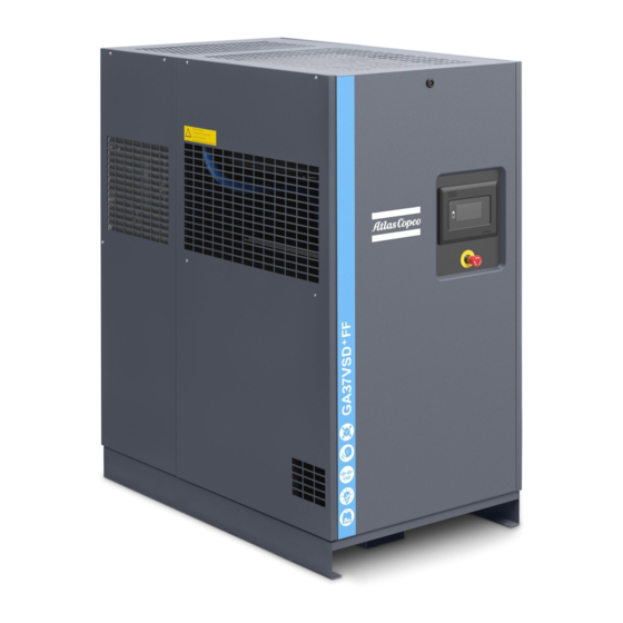
Instruction book General description Introduction Introduction GA 11+ up to GA 30 are single-stage, oil-injected screw compressors driven by an electric motor. GA 11+ up to GA 26+ are controlled by the Elektronikon Touch or Swipe controller based on the voltage. GA 30 is controlled by the Elektronikon Swipe controller. - Page 15 Instruction book Open side view GA, with integrated dryer The compressors have an air dryer which is integrated in the sound-insulated bodywork. The dryer removes condensate from the compressed air by cooling the air to near freezing point. Front view 2920 7118 31...
- Page 16 Instruction book Open side view Reference Name Air filter Air receiver Air outlet Air cooler Oil cooler Automatic condensate outlet Manual condensate outlet Refrigerant dryer Compressor element Electronic water drain Elektronikon Touch controller Cooling fan Motor of the compressor Oil filter Oil separator Emergency stop button Electric cabinet...
-
Page 17: Flow Diagram
Instruction book Flow diagram GA 11+ up to GA 30, without integrated dryer GA 11+ up to GA 30, with integrated dryer 2920 7118 31... -
Page 18: Condensate System
Instruction book Reference Description Air inlet Air/oil mixture Wet compressed air Condensate Air flow Air comes in through filter (AF) and inlet valve (IV) and is compressed in the compressor element (E). A mixture of compressed air and oil flows into the air receiver/oil separator (AR), where oil and air are separated. - Page 19 Instruction book Location of the electronic water drain (without integrated dryer) Location of the electronic water drain (with integrated dryer) The condensate collects in the condensate trap (MT) of the air cooler. On units with integrated dryer, the condensate formed in the dryer collects in the lower part of the heat exchanger/ evaporator.
- Page 20 Instruction book Condensate drain connections, units without integrated dryer Condensate drain connections, units with integrated dryer Reference Designation Automatic drain connection Manual drain connection Electronic water drain (LD200) The Test button (2) on top of the drain can be used in three different ways, according the situation: 2920 7118 31...
- Page 21 Instruction book • When pressed during normal operation, it starts the manual drain test. • When pressed during an alarm, it resets the control logic. • By pressing the Test button for at least 5 seconds, the self diagnosis routine will start. LED explanation Green and red LED alternating on/off for 6 seconds after switching on.
-
Page 22: Regulating System
Instruction book Red LED blinking fast If cleaning routine 1 is completed (after 30 cycles) but still unsuccessful, cleaning routine 2 is activated. This routine will open (3 sec) and close (60 sec) the drain’s valve until a floater is in lower position, so the water is completely drained. -
Page 23: Electrical System
Instruction book • Underpressure from the compressor element causes loading plunger (LP) to move downwards and inlet valve (IV) to open fully. Air delivery is 100%, the compressor runs loaded. Unloading If the air consumption is less than the air output of the compressor, the net pressure increases. When the net pressure reaches the unloading pressure, solenoid valve (Y1) is de-energised. -
Page 24: Air Dryer
Instruction book Reference Designation Transformer Circuit breaker Contactor Contactor Contactor Electrical diagrams The complete electrical diagram can be found in the electric cabinet as well as in the technical documentation, supplied with the unit. Air dryer Flow diagram Air dryer Reference Name Air inlet... - Page 25 Instruction book Reference Name Capillary Bypass valve Condenser cooling fan Pressure switch, fan control Liquid separator Compressed air circuit Compressed air enters the heat exchanger (1) and is cooled by the outgoing, cold, dried air. Water in air starts to condense. Then, the air flows through the heat exchanger/evaporator (2), where the refrigerant evaporates.
-
Page 26: Elektronikon™ Swipe Controller
Instruction book Elektronikon™ Swipe controller Controller The Elektronikon™ Swipe controller Introduction The controller has following functions: • Controlling the unit • Protecting the unit • Monitoring components subject to service • Automatic restart after voltage failure (ARAVF) Automatic control of the unit The controller maintains the net pressure between programmable limits by automatically loading and unloading the unit. - Page 27 Instruction book Protecting the unit Shutdown If the element outlet temperature exceeds the programmed shutdown level, the unit will be stopped. The unit will also be stopped in case of overload of the drive motor or fan motor. Before remedying, consult the Safety precautions.
-
Page 28: Control Panel
Instruction book Control panel Control panel Parts and functions Reference Designation Function Warning sign Flashes in case of a shut-down, is lit in case of a warning condition. Service sign Is lit when service is needed. Operation sign Is lit when the unit is running. Voltage sign Indicates that the voltage is switched on. -
Page 29: Icons Used
Instruction book Icons used Menu icons Menu Icon Main screen Machine Settings Aux. Equipment Parameters Data Service Controller Settings Information Status icons Icon Description Motor Stopped Motor Stopped Wait Running Unloaded Manual Unload Running Unloaded Wait Running Loaded Running Loaded Wait Machine Control Mode, Local 2920 7118 31... -
Page 30: Menu
Instruction book Machine Control Mode, Remote Machine Control Mode, LAN Auto Restart After Voltage Failure (ARAVF) System icons Icon Description Basic User Advanced User Service User Change between screens (indication) Reset This chapter gives a general survey of available icons. Not all icons mentioned in this chapter are applicable to every machine. - Page 31 Instruction book Menu structure Reference Designation Function Main screen Next to the main screen, a maximum of 3 extra values can be shown. Machine settings Setpoints, Regulation settings and Control parameters can be viewed and modified through this menu. Aux. Equipment Settings for auxiliary equipment can be viewed and modified through parameters this menu.
-
Page 32: Main Screen
Instruction book This is the main menu structure. The structure can be different depending on the configuration of the unit. Select or modify a setting Several settings can be modified. The process of selecting or modifying a setting anywhere in the menu is basically the same. - Page 33 Instruction book Description Reference Designation Function Screen information On the main screen, the screen information bar shows the current status of the machine. When scrolling through menus, the name of the current menu item is shown. Access level icon The access level icon shows the current access level setting.
- Page 34 Instruction book Example Setpoint used Starting from the main screen, swipe left until the Setpoint used screen is shown. To switch to a different setpoint, swipe up or down on the left vertical swipebar or tap next to the corresponding square. Manual unload Starting from the main screen, swipe left until the Manual unload screen is shown.
-
Page 35: Machine Settings Menu
Instruction book To reset the alarm, press the confirm button under the reset icon. To cancel without resetting, press the cancel button under the red ‘X’ icon. Before remedying, consult the Safety precautions. Before resetting a warning or shutdown message, always solve the problem. Frequently resetting these messages without remedying may damage the unit. - Page 36 Instruction book Setpoint 2 Starting from the Machine Settings menu, swipe left until the Setpoint 2 screen is shown. To select a load and unload setpoint, or to modify the values, see section Select or modify a setting. Regulation Starting from the Machine Settings menu, swipe left until the Regulation screen is shown. To select a menu item, or to change the setting, see section Select or modify a setting.
-
Page 37: Auxiliary Equipment Parameters Menu
Instruction book The controller has a built-in function to automatically restart the compressor when voltage is restored after voltage failure. This function is deactivated in compressors leaving the factory and can only be modified after entering a password, please consult your supplier to activate this function. -
Page 38: Data Menu
Instruction book SmartBox Starting from the Aux. Equipment parameters menu, swipe left until the Internal SmartBox screen is shown. The reception quality of the internal antenna can be monitored. To select a menu item, or to change the setting, see section Select or modify a setting. -
Page 39: Service Menu
Instruction book Counters Starting from the Data menu, swipe left until the Counters screen is shown. Select To select a different item, swipe up or down on the left vertical swipebar. Inputs Starting from the Data menu, swipe left until the Inputs screen is shown. Select To select a different item, swipe up or down on the left vertical swipebar. - Page 40 Instruction book Swipe left to navigate to the following screens: • Next service • Safety valve test Procedure To view the Service menu: 1. Use the controller as a Service user Controller settings menu to change the user profile. 2. Tap the Home button on top of the screen to go to the main screen.
-
Page 41: Controller Settings Menu
Instruction book On the horizontal swipebar, tap ‘V’ to confirm or ‘X’ to decline. 3.10 Controller settings menu Function The Controller Settings menu provides the ability to view and modify several settings of the controller. Swipe left to navigate to the following screens: •... - Page 42 Instruction book Enter a password The Service user profile is protected by a password. After selecting the Service user profile, the following screen pops up: The user can enter the password by swiping up or down on the right vertical swipebar to select the first digit.
-
Page 43: Information Menu
Instruction book Do not forget to turn on ethernet settings after changing these settings. Otherwise the controller can’t connect anymore! Display Timeout Starting from the Controller Settings menu, swipe left until the Display Timeout screen is shown. Display timeout is used to save energy and save the lifetime of the display. Timer starts after last operator actions on the push buttons or swipe bars. - Page 44 Instruction book • BOOT Software: nr 2920 7118 31...
-
Page 45: Elektronikon™ Touch Controller
Instruction book Elektronikon™ Touch controller Controller The Elektronikon™ Touch controller Introduction The controller has the following functions: • Controlling the unit • Protecting the unit • Monitoring components subject to service • Automatic Restart After Voltage Failure (ARAVF) Automatic control of the unit The controller maintains the net pressure between programmable limits by automatically loading and unloading the unit (fixed speed units) or by adapting the motor speed (units with frequency converter). - Page 46 Instruction book Protecting the unit Shutdown Several sensors are provided on the unit. If one of the measured signals exceeds the programmed shutdown level, the unit will be stopped. Example: If the element outlet temperature exceeds the programmed shutdown level, the unit will be stopped.
-
Page 47: Control Panel
Instruction book Control panel Control panel Parts and functions Reference Designation Function Touch screen Shows the unit operating condition and several icons to navigate through the menu. The screen can be operated by touch. Warning sign Flashes in case of a shut-down and is lit in case of a warning condition. -
Page 48: Icons Used
Instruction book Icons used Menu icons Menu Icon Menu Icon Menu Icon Data Status Inputs Outputs Counters Aux. Equipment Converters Parameters Service Service Overview Service Plan Service History Service functions Clean Screen Week Timer Week Remaining Running Time Event History Saved Data 2920 7118 31... - Page 49 Instruction book Menu Icon Menu Icon Menu Icon Machine Alarms Settings Regulation Control Parameters Aux. Equipment Converter(s) Parameters Internal SmartBox Auto Restart Controller Network Ethernet Settings Settings Settings CAN Settings Localisation Language Date/Time Units User Password Help Information Status icons Icon Description Motor Stopped...
- Page 50 Instruction book Motor Stopped Wait Running Unloaded Manual Unload Running Unloaded Wait Running Loaded Failed to Load Running Loaded Wait Manual Stop Machine Control Mode, Local Machine Control Mode, Remote Machine Control Mode, LAN Automatic Restart After Voltage Failure Week Timer Active System icons Icon Description...
- Page 51 Instruction book Antenna 50% Antenna 75% Antenna 100% Change between screens (indication) Energy recovery Dryer Element Drain(s) Analogue Output Menu Reset Auto Restart Filter(s) Cooler Valve(s) Power Meter Input icons Icon Description Pressure 2920 7118 31...
-
Page 52: Main Screen
Instruction book Temperature Special Protection Open Closed This chapter gives a general survey of available icons. Not all icons mentioned in this chapter are applicable to every machine. Main screen Function The Main screen is the screen that is shown automatically when the voltage is switched on. It is switched off automatically after a few minutes when there is no touch input. -
Page 53: Quick Access Screen
Instruction book Reference Designation Function Alarm button The alarm button can be tapped to show the current alarms. If an alarm occurs, the icon on the button will be red. Service button The service button can be tapped to show the service information. -
Page 54: Menu Screen
Instruction book Function Description Setpoints Several setpoints can be modified by tapping this icon. Control mode The control mode can be changed by tapping this icon. • Local control via start/stop buttons • Remote control via digital input(s) • LAN control via the network. When in Remote or LAN control, the start/stop buttons on the controller will not work. - Page 55 Instruction book Reference Designation Function Service The service menu contains the Service information. The ‘Clean screen’ function can be used to clean the touchscreen. Week timer Multiple Week timers and a Remaining running time can be set through this menu. Event history In case of an alarm, the Status information of the unit is saved and can be viewed through this menu.
-
Page 56: Data Menu
Instruction book Data menu Function This screen is used to display the following submenus: • Status • Inputs • Outputs • Counters • Aux. Equipment These submenus can be entered by tapping the icons. Procedure To enter the Data menu screen: 1. - Page 57 Instruction book If an alarm is active, it can be viewed by tapping the alarm message. To reset an alarm, tap the reset button (1). Before remedying, consult the Safety precautions. Before resetting a warning or shutdown message, always solve the problem. Frequently resetting these messages without remedying may damage the unit.
-
Page 58: Service Menu
Instruction book This menu shows an overview of all actual hours and counters of the unit and controller. Auxiliary equipment menu Tap the Aux. Equipment icon to enter the Aux. equipment menu. This menu shows an overview of all auxiliary equipment fitted. Service menu Function This screen is used to display the following submenus:... - Page 59 Instruction book Description Reference Designation Service Service functions (Only visible as advanced user) Clean screen Service menu Tap the Service icon to enter the Service menu. This menu shows the remaining Running Hours and the remaining Real Time Hours until the next service.
-
Page 60: Week Timer Menu
Instruction book Depending on the machine, this menu can have a different set of functions. Many of them are password protected, as they are only accessible for authorized personnel. Clean screen Tap the Clean Screen icon to start the 15 seconds countdown to perform cleaning of the touchscreen. -
Page 61: Event History Menu
Instruction book Description Reference Designation Function Add or select week If less than 4 weeks are programmed, tap the ‘+’ button to add a week. Remove week Tap to remove a programmed week timer. Activate week timer A selection screen pops up. The user can choose the correct week by tapping ‘–’... -
Page 62: Machine Settings Menu
Instruction book Reference Designation Saved Data Saved data Tap the Saved Data icon to enter the Saved Data menu. Scroll through the items swiping up and down in this list. The event date and time is shown at the right side of the screen. Press on one of the items in the list for more information reflecting the status of the unit when the shutdown occurred. - Page 63 Instruction book Description Reference Designation Alarms menu Regulation menu Control Parameters menu Aux. Equipment Parameters menu Auto Restart menu Alarms menu Tap the Alarms icon to enter the Alarms menu. A list of all alarms is shown. When pressing on one of the items in this list, the warning and/or shutdown levels are shown for this alarm.
- Page 64 Instruction book When tapping a list item, a selection screen pops up. The user can modify the setting by tapping ‘–’ or ‘+’ and can confirm by tapping ‘V’ or decline by tapping ‘X’. Change a selection When tapping a list item, a selection screen pops up. The user can change the selection by swiping up or down and confirm by tapping ‘V’...
-
Page 65: Controller Settings Menu
Instruction book Through this menu, the automatic restart can be activated. The activation is password protected. The automatic restart settings can also be changed. Enter a password When tapping a password protected item, a selection screen pops up. The user can enter the password by swiping up or down to select the desired number. - Page 66 Instruction book Reference Designation Network Settings menu Localisation menu User Password menu Help menu Information menu Network settings menu Tap the Network Settings icon to enter the Network Settings menu. Ethernet Settings The list of Ethernet Settings is shown. When ethernet is turned off, the settings can be modified. CAN Settings The list of CAN Settings is shown.
- Page 67 Instruction book The date and time settings of the controller can be modified through this menu. Units The units displayed can be modified through this menu. Modify a setting When tapping a list item, a selection screen pops up. The user can modify the setting by tapping ‘–’...
-
Page 68: Access Level
Instruction book This menu shows information about the controller. 4.13 Access level Function Through this pop-up screen the access level settings can be viewed or changed. Procedure The Access Level screen can be viewed or changed by tapping the Access Level button at the upper right corner of the screen. - Page 69 Instruction book Service access level Tap the Service access level icon (1) and confirm (2). The screen information bar (1) now shows the current status of the unit instead of the machine serial number. The Received Signal Strength Indicator (RSSI) value is now shown in the Internal SmartBox menu.
-
Page 70: Installation
Instruction book Installation Dimension drawings The dimension drawing can be found in the technical documentation, supplied with the unit. Dimension drawing Model 9828 5323 21 GA 11+, GA 15+, GA 18+, GA 22+, GA 26+, GA 30 Text on drawing Explanation, Electrical cable passage Electric cable entry... - Page 71 Instruction book Compressor room example Compressor room example Text on image Ventilation proposals Minimum free area to be reserved for the compressor installation All piping has to be connected stress free to the compressor. Foundation, placement of the compressor unit Install the compressor unit on a solid, level floor, suitable for the compressor mass.
- Page 72 Instruction book Transportation brackets Before starting the compressor for the first time, check that all red-colored transportation brackets/bolts have been removed. They can be under the drivetrain, separation vessel and the compressor of the integrated dryer (optional). Electrical connections • The supply voltage on the compressor terminals must not deviate more than 10% of the nominal voltage.
- Page 73 The drain pipes to the drain collector may not dip into the water of the drain collector. Atlas Copco has oil/water separators (type OSD or OSCi) to separate oil from the condensate to ensure that the condensate meets the requirements of the environmental codes. Drain pipes of...
- Page 74 Instruction book different compressors may not be interconnected before the (atmospheric) collector as this can damage the electronic drains. Ventilation The compressor room should have proper ventilation in order to keep the air inlet temperature of the compressor under control. The maximum air temperature at the compressor intake is 46°C (115°F), the minimum temperature is 0°C (32°F).
- Page 75 Instruction book = (1.06 N + 1.2 D)/ΔT = required ventilation capacity in m N = nominal power of the compressor motor in kW D = electric power of the dryer in kW ΔT = temperature increase in the compressor room in C For air-cooled compressors and ventilation alternatives 2 and 4 The fan capacity should match the compressor fan capacity at a pressure head equal to the pressure drop over the air ducts.
- Page 76 Instruction book Air delivery pipe The pressure drop over the air delivery pipe can be calculated from: 1.85 Δp = (L x 450 x Q ) / (d x P) d = inner diameter of the pipe in mm Δp = pressure drop in bar (recommended maximum: 0.1 bar (1.5 psi)) L = length of the pipe in m P = absolute pressure at the compressor outlet in bar(a) = free air delivery of the compressor in l/s...
- Page 77 Instruction book Air receiver Install the air receiver (to be purchased separately) in a frost free room and on a solid level floor, suitable for its mass. The air receiver must be fitted with a correctly sized and approved safety valve that is directly connected with the vessel.
-
Page 78: Electrical Connections
Instruction book Remove the plastic plugs (if provided) from the compressor water pipes and connect the pipes to the cooling water circuit. Outdoor/ altitude operation Compressors can be sold with the option rain protection. With this, the compressor can be installed outside under a shelter, in frost free conditions. - Page 79 Instruction book Electrical connections Reference Designation Customer’s installation All voltages (50 and 60 Hz) The correct position for the electrical connection can be found on the dimension drawings. Instructions 1. Provide an isolating switch. 2. Check that the motor cables and wires inside the electric cabinet are clamped tight to their terminals.
- Page 80 Instruction book On compressors equipped with an Elektronikon™ Swipe controller, the controller is provided with potential free auxiliary NO contacts (NO = normally open) (K05, K07 and K08) for remote indication of: • Manual load/unload or automatic operation (K07) • Warning condition (K08) •...
-
Page 81: Pictographs
Instruction book Pictographs Description Pictographs 2920 7118 31... - Page 82 Instruction book Reference Designation Warning: Always read the manual, switch off the voltage, depressurise compressor and lock out/ tag out before repairing. IF the rotation direction is wrong, open the isolating switch in the voltage supply line and reverse two incoming electric lines. Warning, voltage Automatic condensate drain Stop the compressor before cleaning the coolers...
-
Page 83: Options
Instruction book Options Energy recovery 6.1.1 Energy recovery unit Description A large part of the energy required for any compression process is transformed into heat. The major part of the compression heat is dissipated through the oil system. Energy Recovery (ER) systems are designed to recover most of this heat by transforming it into warm or hot water without any adverse effects on compressor performance. - Page 84 Instruction book Energy Recovery (ER) unit Main components of the ER unit (typical installation) Reference Designation Water inlet pipe Water outlet pipe Temperature sensor, water inlet pipe Temperature sensor, water outlet pipe Oil drain valve Oil line from compressor oil separator vessel to ER unit Oil line from ER unit to oil filter housing Location of heat exchanger by-pass valve (BV2) Heat exchanger...
- Page 85 Instruction book 6.1.2 Energy recovery systems General The energy recovery systems can be applied as low temperature rise/high water flow systems or as high temperature rise/low water flow systems. Low temperature rise/high water flow systems For this type of application, the temperature difference between the water in the energy recovery system and the compressor oil is low.
- Page 86 Instruction book (BV2) controls the oil flow through the oil/water heat exchanger (HE) of the ER unit. Both valves consist of an insert (thermostat) mounted in a housing. Flow diagram of compressor with energy recovery system Reference Designation Reference Designation Thermostatic bypass valve of ER Oil filter unit...
- Page 87 Instruction book Position of bypass ball valves ER label Attention: It is NOT allowed to use the ball valves at an in-between position! Energy recovery system in use (see drawing) Bypass valves in position (A): the heat exchanger (HE) is integrated in the water side of the ER. •...
- Page 88 Instruction book As soon as the oil temperature reaches the set point (opening temperature) of bypass valve (BV1), the valve starts closing off the bypass over the oil cooling system, gradually allowing the oil to flow through the heat exchanger (HE). As the oil temperature rises to approx. 75 ˚C (167 ˚F) , all the oil passes through the cooling system.
- Page 89 Instruction book Heat exchanger (HE) If the temperature rise over the energy recovery system declines over a period of time with the same basic working conditions, the heat exchanger should be inspected. To clean the oil side, soak the heat exchanger in a degreasing solution. To remove scale formation in the water compartment, a proper descaling process should be applied.
- Page 90 Instruction book Type of cooling system Materials Standard Energy recovery Closed loop Containing copper 7.5 - 9.3 7.5 - 9.3 Stainless steel with carbon 7.5 - 9.3 7.5 - 9.3 steel and / or cast iron Stainless steel only 6 - 9.3 6 - 9.3 The values in bold are rejection limits.
- Page 91 Instruction book Total Temperature Ca hardness dissolved (°C) (ppm CaCO Alkalinity solids (ppm (mg/l) CaCO < 30 0 - 1 9 - 11 10 - 11 30 - 320 2 - 6 12 - 14 12 - 14 > 320 7 - 11 15 - 17 15 - 17...
- Page 92 Instruction book For energy recovery systems, the limit is 100 ppm. 7. Sulphates (SO Sulphate (ppm) Type of cooling system Standard Energy recovery Single pass < 1000 < 200 Recirculating (with tower) < 1000 not applicable Closed loop < 400 <...
- Page 93 Instruction book Biology (CFU/ml) Type of cooling system Standard Energy recovery Single pass < 10 / < 10 < 10 / < 10 Recirculating (with tower) not applicable < 10 / < 10 Closed loop < 10 / < 10 <...
- Page 94 Instruction book Temperature input Minimum Nominal Maximum setting setting setting Water inlet temperature of energy recovery ˚C Water inlet temperature of energy recovery ˚F Energy recovery water outlet temperature ˚C Energy recovery water outlet temperature ˚F To modify a setting, consult the relevant section in the description of the controller. Recoverable energy The recoverable energy can be calculated from: RECOVERED ENERGY (kW) = 4.2 x water flow (l/s) x water temperature rise (˚C)
-
Page 95: Main Switch
Instruction book Main switch A built-in main switch can be ordered as a sales option. Electrical connections Electric connection diagram (typical example) Reference Designation Main Switch Customer's installation Note The complete electrical diagram can be found in the electrical cubicle Dryer bypass Description This kit allows the user to bypass the integrated dryer in case of a failure. -
Page 96: Freeze Protection
Instruction book Dryer bypass components Reference Name Straight bypass pipe at the outlet of the cooler. T-joint and pipe to connect the straight pipe to the dryer. Ball valve at the T-joint. Dryer outlet. Ball valve at the outlet of the dryer bypass. Function During normal operation of the compressor, the ball valve (3) always remains open and air from the after cooler flows through the dryer to the dryer outlet. - Page 97 Instruction book Freeze protection components Reference Name S0’ Main switch (Customer installation) F0’ Main protection (Customer installation) Tracing for electronic water drain on after cooler Tracing for electronic water drain on dryer (Units with integrated dryer only) Tracing for vessel Heater for electrical cubicle TSLL91 Thermostat CSA-UL/IEC...
-
Page 98: Heavy Duty Filter
Instruction book Heavy duty filter Description This option will extend the oil change interval and the interval on the inlet filter change in dusty environments like for instance cement plants and desert conditions. This is done by adding a pre- filtration through tangential inlet of the air and including a secondary filter element. - Page 99 Instruction book Prefilter components Reference Name 1–4 Prefilter 2920 7118 31...
-
Page 100: Operating Instructions
Instruction book Operating instructions Initial start-up The operator must apply all applicable Safety precautions. For the location of the air outlet valve and the drain connections, see sections Introduction Condensate system. Preparations 1. Consult the sections Electrical cable size, Installation proposal Dimension drawings. - Page 101 Take care that no dirt drops into the oil system. Refit and tighten the filler plug (FC). 10. Provide labels, warning the operator that: • The compressor may automatically restart after voltage failure (if activated, consult Atlas Copco). • The compressor is automatically controlled and may be restarted automatically . 11. Open the air outlet valve.
-
Page 102: Before Starting
Instruction book Start and run the compressor for a few minutes. Check that the compressor operates normally. 12. Check the rotation direction of the fan motor. For this purpose, a sheet is fixed to the top grating of the compressor. a. -
Page 103: Starting
Instruction book Position of oil level sight glass Starting For the position of the air outlet valve and the drain connections, see sections Introduction Condensate system. Control panel Elektronikon™ Touch 2920 7118 31... -
Page 104: During Operation
Instruction book Control panel Elektronikon™ Swipe Procedure 1. Open the air outlet valve. 2. Switch on the voltage. Check that voltage on LED (5) lights up. 3. Press start button (7) on the control panel. The compressor starts running and the automatic operation LED (4) lights up. - Page 105 Instruction book Checking the oil level Control panel Elektronikon™ Touch Control panel Elektronikon™ Swipe 2920 7118 31...
-
Page 106: Checking The Display
Instruction book Regularly check the oil level. To do so: 1. Press stop button (6). 2. A few minutes after stopping, the oil level should be between the oil filler neck (FC) and the bottom of the sight glass (Gl). 3. - Page 107 Instruction book Control panel Elektronikon™ Touch Check the main screen (1) regularly for readings and messages. The display normally shows the compressor. outlet pressure, while the status of the compressor is indicated by pictographs. Remedy the trouble if alarm LED (2) is lit or flashes, see section Shutdown warning, Shutdown and Problem solving.
- Page 108 Instruction book Control panel Elektronikon Swipe™ Check the main screen (6) regularly for readings and messages. The display normally shows the compressor. outlet pressure, while the status of the compressor is indicated by pictographs. Remedy the trouble if alarm LED (1) is lit or flashes, see section Shutdown warning, Shutdown and Problem solving.
-
Page 109: Stopping
Instruction book Stopping Control panel Elektronikon™ Touch Control panel Elektronikon™ Swipe 2920 7118 31... -
Page 110: Taking Out Of Operation
Instruction book Procedure Step Action Press stop button (6). Automatic operation LED (4) goes out and the compressor stops after 30 seconds of unloaded operation. To stop the compressor in the event of an emergency, press emergency stop button. Alarm LED flashes (2). •... -
Page 111: Maintenance
For overhauling or carrying out preventive maintenance, service kits are available (see section Service kits). Service agreements Contact Atlas Copco to set up a tailor-made service agreement. It will ensure optimum operational efficiency, minimize downtime and reduce the total life cycle cost. General When servicing, replace all removed O-rings and washers. - Page 112 Instruction book which service plans are to be carried out. After servicing, the intervals must be reset, see section Service menu. Service plans for compressors with an Elektronikon controller Besides the daily and 3-monthly checks, preventive maintenance actions are specified in the schedule below.
- Page 113 In order to achieve the best machine performance and guarantee the reliability, it is required to use genuine Atlas Copco Lubricants. Their tailor made formulation is the result of years of field experience, research and in-house development. Consult the Spare Parts list for part number information.
- Page 114 40°C (104°F) above 105°C (221°F) use Roto Synthetic Fluid Xtend Duty Note: the presence of dust and/or high humidity may require a shorter exchange interval. Consult Atlas Copco. Exchange interval for Roto Synthetic Fluid Ultra Ambient temperature Element outlet...
-
Page 115: Oil Specifications
• For change of oil contact Atlas Copco for the correct procedure. • For changing of one type of oil to another type of oil consult Atlas Copco for the correct procedure as this is not allowed in some conditions. -
Page 116: Drive Motor
Roto Synthetic Fluid XTEND DUTY. Roto Synthetic Fluid XTEND DUTY Atlas Copco's Roto Synthetic Fluid XTEND DUTY is a high quality synthetic 8000 hours lubricant for oil injected screw compressors which keeps the compressor in excellent condition. Because of its excellent oxidation stability, Roto Synthetic Fluid XTEND DUTY can be used for compressors operating at ambient temperatures between 0 ˚C (32 ˚F) and 46 ˚C (115 ˚F). -
Page 117: Air Filter
Instruction book Air filter Location of air filter Procedure 1. Stop the compressor. Switch off the voltage. 2. Remove the cover of the air filter (AF) by opening the clip system. Remove the filter element. 3. Fit the new element and the cover. 4. - Page 118 Instruction book 2. Remove the vent plug (VP) of the oil cooler. Vent plug, oil cooler 3. Open the oil drain valve (Do). • Hold the oil drain hose (1) downward to drain the oil. • Drain oil from outlet housing. •...
-
Page 119: Coolers
Instruction book • Remove the oil separator (OS). Be aware that this filter has a left thread connection. • Collect the oil in a collector and deliver it to the local collection service. Refit the vent plugs after draining. • Close the oil drain valve (Do). •... -
Page 120: Dryer Maintenance Instructions
Instruction book Procedure for compressors with dryer. Location of the condenser of the dryer • Remove dirt on the inlet of the condenser (6) with a fibre brush. • Clean with an air jet in the reverse direction to normal flow. •... -
Page 121: Safety Valves
Instruction book Safety valves Location of safety valve Testing The safety valve (SV) test can only be performed by authorized personnel and is protected by a security code. Refer to Elektronikon™ Touch controller. If the safety valve does not open at the set pressure stamped on the valve, it needs to be replaced. -
Page 122: Service Kits
Atlas Copco parts while keeping the maintenance budget low. Also a full range of extensively tested lubricants, suitable for your specific needs is available to keep the compressor in excellent condition. -
Page 123: Problem Solving
Instruction book Problem solving Warning Before carrying out any maintenance, repair work or adjustment, stop compressor, wait 3 minutes and close the air outlet valve. Press the test button on top of the electronic water drain until the air system between the air receiver and outlet valve is fully depressurized. - Page 124 Oil separator clogged Have element replaced. Air leakage Have leaks repaired. Safety valve leaking Have valve replaced. Compressor element out of order Consult Atlas Copco. Condition Fault Remedy Safety valve blows Minimum pressure valve Check and have defective parts malfunctioning replaced.
- Page 125 Instruction book Condition Fault Remedy Low Load Alarm triggeredon VSD+ Solenoid valve malfunctioning Replace valve. units: Compressor running with too low oil temperature over a longer period of time Extreme low usage of compressor Increase loading profile (longer and/or more load cycles required).
- Page 126 Instruction book Condition Fault Remedy Condenser pressure too high See above. or too low Shortage of refrigerant Have circuit checked for leaks and recharged if necessary. 2920 7118 31...
-
Page 127: Technical Data
Instruction book Technical data 10.1 Readings on display Elektronikon Touch controller Elektronikon Swipe controller 2920 7118 31... -
Page 128: Electric Cable Size And Fuses
Instruction book Important The readings mentioned below are valid under the reference conditions (see section Reference conditions and limtations). Reference Reading Air outlet pressure Depends on the setpoint (desired net pressure). Compressor element Approx. 80 ˚C (176 ˚F) (ambient temperature 20 °C + 60 °C) outlet temperature Dewpoint temperature Approx. - Page 129 Instruction book Currents and fuses IEC approval Compressor type Maximu Maximu m fuse m fuse gL/gG gL/gG GA11+ GA11+ GA11+ GA11+ GA11+ Compressor type Maximu Maximu m fuse m fuse gL/gG gL/gG GA15+ GA15+ GA15+ GA15+ GA15+ Compressor type Maximu Maximu m fuse m fuse...
- Page 130 Instruction book Compressor type Maximu Maximu m fuse m fuse gL/gG gL/gG GA22+ GA22+ GA22+ GA22+ GA22+ Compressor type Maximu Maximu m fuse m fuse gL/gG gL/gG GA26+ GA26+ GA26+ GA26+ GA26+ Compressor type Maximu Maximu m fuse m fuse gL/gG gL/gG GA30...
- Page 131 Instruction book UL/cUL approval Compressor type Maximu Maximu m fuse m fuse form II form II GA11+ GA11+ GA11+ TRI GA11+ TRI GA11+ TRI Compressor type Maximu Maximu m fuse m fuse form II form II GA15+ GA15+ GA15+ TRI GA15+ TRI GA15+ TRI Compressor type...
- Page 132 Instruction book Compressor type Maximu Maximu m fuse m fuse form II form II GA22+ GA22+ GA22+ TRI GA22+ TRI GA22+ TRI Compressor type Maximu Maximu m fuse m fuse form II form II GA26+ GA26+ GA26+ TRI GA26+ TRI GA26+ TRI Compressor type Maximu...
- Page 133 Instruction book secondary of the transformer. The indicated fuse values are valid for the fuses to be installed by the customer. Setting motor overload relay (F21) Overload relay and fuses GA11+ GA15+ GA18+ GA22+ GA26+ GA30 Freq (Hz) Voltage (V) (A) UL/cUL Setting fan motor overload protection (Q15/ F15) Circuit breaker...
- Page 134 Instruction book Cable sizing according IEC The tables below indicate the current carrying capacities of cables for 3 commonly used installation methods, calculated according to standard 60364-5-52 - electrical installations of buildings part 5 - selection and erection equipment and section 52 - current carrying capacities in wiring systems.
- Page 135 Instruction book Ambient temperature Cable section 30 °C 40 °C 45 °C 50 °C 55 °C 70 mm² < 184 A < 160 A < 145 A < 131 A < 112 A 95 mm² < 223 A < 194 A <...
- Page 136 Instruction book • The table for B2 and ambient temperature = 45 ° C allows a maximum current of 93 A for a 50 mm² cable. For a cable of 70 mm², the maximum allowed current is 118 A, which is sufficient. Therefore, use a 3 x 70 mm² + 35 mm² cable. If method C is used, 50 mm²...
-
Page 137: Reference Conditions And Limitations
Instruction book < 100 A: use AWG8 < 200 A: use AWG6 < 300 A: use AWG4 Always check the voltage drop over the cable (less than 5 % of the nominal voltage is recommended). Example of supply cable calculation: I = 128 A, maximum ambient temperature is 45 °C, recommended fuse = 150 A •... -
Page 138: Compressor Data
Instruction book 10.4 Compressor data Reference conditions All data specified below apply under reference conditions, see section Reference conditions and limitations. GA 11 Units 7.5 bar 8.5 bar 10 bar 13 bar 100 psi 125 psi 150 psi 175 psi Frequency Reference working bar(e) - Page 139 Instruction book Units 7.5 bar 8.5 bar 10 bar 13 bar 100 psi 125 psi 150 psi 175 psi Power consumption 0.35 0.35 0.35 0.35 0.35 0.35 0.35 0.35 (dryer at full load), Full-Feature units Power consumption 0.47 0.47 0.47 0.47 0.47 0.47...
- Page 140 Instruction book Units 7.5 bar 8.5 bar 10 bar 13 bar 100 psi 125 psi 150 psi 175 psi Temperature of air ˚F leaving outlet valve (approx.) Temperature of air ˚C leaving outlet valve (approx.), Full- Feature units Temperature of air ˚F leaving outlet valve (approx.), Full-...
- Page 141 Instruction book Units 7.5 bar 8.5 bar 10 bar 13 bar 100 psi 125 psi 150 psi 175 psi Reference working psig pressure Pressure drop over bar(e) 0.14 0.14 0.14 0.14 0.14 0.14 0.14 0.14 dryer, Full-Feature units Pressure drop over psig 2.03 2.03...
- Page 142 Instruction book Units 7.5 bar 8.5 bar 10 bar 13 bar 100 psi 125 psi 150 psi 175 psi Oil capacity Imp gal 3.1 Oil capacity cu.ft 0.50 0.50 0.50 0.50 0.50 0.50 0.50 0.50 Sound pressure dB(A) level, Pack and Pack Full-Feature (according to ISO 2151 (2004))
- Page 143 Instruction book Units 7.5 bar 8.5 bar 10 bar 13 bar 100 psi 125 psi 150 psi 175 psi Power consumption 0.48 0.48 0.48 0.48 0.48 0.48 0.48 0.48 (dryer at full load), Full-Feature units Power consumption 0.64 0.64 0.64 0.64 0.64 0.64...
- Page 144 Instruction book Units 7.5 bar 8.5 bar 10 bar 13 bar 100 psi 125 psi 150 psi 175 psi Temperature of air ˚F leaving outlet valve (approx.) Temperature of air ˚C leaving outlet valve (approx.), Full- Feature units Temperature of air ˚F leaving outlet valve (approx.), Full-...
- Page 145 Instruction book Units 7.5 bar 8.5 bar 10 bar 13 bar 100 psi 125 psi 150 psi 175 psi Reference working psig pressure Pressure drop over bar(e) 0.14 0.14 0.14 0.14 0.14 0.14 0.14 0.14 dryer, Full-Feature units Pressure drop over psig 2.03 2.03...
-
Page 146: Technical Data Controller
Instruction book Units 7.5 bar 8.5 bar 10 bar 13 bar 100 psi 125 psi 150 psi 175 psi Oil capacity Imp gal 3.52 3.52 3.52 3.52 3.52 3.52 3.52 3.52 Oil capacity cu.ft 0.57 0.57 0.57 0.57 0.57 0.57 0.57 0.57 Sound pressure... -
Page 147: Instructions For Use
Instruction book Instructions for use Air/oil separator vessel This vessel can contain pressurised air; this can be potentially dangerous if the equipment is misused. This vessel must only be used as a compressed air/oil separator and must be operated within the limits specified on the data plate. No alterations must be made to this vessel by welding, drilling or any other mechanical methods without the written permission of the manufacturer. -
Page 148: Guidelines For Inspection
Instruction book Guidelines for inspection Guidelines On the Declaration of Conformity / Declaration by the Manufacturer, the harmonised and/or other standards that have been used for the design are shown and/or referred to. The Declaration of Conformity / Declaration by the Manufacturer is part of the documentation that is supplied with this compressor. -
Page 149: Pressure Equipment Directives
Instruction book Pressure equipment directives Components subject to 2014/68/EU Pressure Equipment Directive The following table contains the necessary information for the inspection of all pressure equipment of category II and higher according to the Pressure Equipment Directive 2014/68/EU and all pressure equipment according to the Simple Pressure Vessel Directive 2014/29/EU. Compressor Component Description... -
Page 150: Declaration Of Conformity
Instruction book Declaration of conformity Typical example of a Declaration of Conformity document (1): Contact address: Atlas Copco Airpower n.v. P.O. Box 100 B-2610 Wilrijk (Antwerp) Belgium (2): Applicable directives (3): Standards used On the Declaration of Conformity / Declaration by the Manufacturer, the harmonized and/or other standards that have been used for the design are shown and/or referred to. - Page 152 COMMITTED TO SUSTAINABLE PRODUCTIVITY We stand by our responsibilities towards our customers, towards the environment and the people around us. We make performance stand the test of time. This is what we call — Sustainable Productivity. www.atlascopco.com...
Need help?
Do you have a question about the GA 11+ and is the answer not in the manual?
Questions and answers