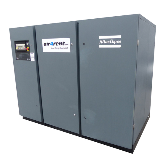
Atlas Copco GA90 Instruction Book
Hide thumbs
Also See for GA90:
- Instruction book (137 pages) ,
- Instruction book (98 pages) ,
- Instruction book (41 pages)
Table of Contents

Summary of Contents for Atlas Copco GA90
- Page 1 Atlas Copco Stationary Air Compressors GA90 - GA110 - GA132 - GA160 - GA200 - GA250 - GA315 GA90 W - GA110 W - GA132 W - GA160 W - GA200 W - GA250 W - GA315 W Instruction book...
-
Page 2: Table Of Contents
The company reserves the right to make changes without prior notice. Contents Leading particulars ....... . 3 4.1.1 Regular service operations . -
Page 3: Leading Particulars
1 LEADING PARTICULARS 1.1 General description GA Full-feature (FF) ® 2920 1475 00... - Page 4 7 M25 51329F 2920 1475 00...
-
Page 5: Main Options
1.1.1 Main options Oil containing frame Full-feature Modulating control Integrated DD filter Heavy-duty air intake filter Integrated OSD Rain protection Electronic drain High ambient temperature version Energy recovery Phase Sequence Relay 50837F 2920 1475 00... - Page 6 50852F 3 20 M26 4 50835F 8 7 9 2920 1475 00...
-
Page 7: Air Flow / Regulating System
PT 1000 thermal protection 1.2.2 Condensate drain system Full-feature DIN/BSP or ANSI/NPT connections 1.2.3 Oil system 1) HD Roto-fluid Cooling air outlet ducting Lifting device 1.2.4 Cooling system On GA, GA W 1.2 Air flow / regulating system (Figs. 1.7 and 1.8) 1.2.5 Regulating system 1.2.1 Air flow 1) - Page 8 Fig. 1.7 GA90/160 Full-feature during unloading Air filter By-pass opening Air receiver Unloader Blow-off channel Oil separator element Unloading valve Chamber, receiver pressure Minimum pressure valve Air cooler Valve Check valve Cooling fan Shield Oil scavenging line Oil coolers Compressor element...
- Page 9 Oil drain plug Thermostatic expansion valve Refrigerant compressor By-pass valve Sight-glass Liquid separator Air outlet valve (customer’s Filter/dryer Low pressure switch installation) Capillary tube Air/refrigerant heat exchanger Condensate trap Fan control switch Air/air heat exchanger Channel High pressure switch By-pass valves Flexible, receiver pressure By-pass valve Insulating block...
-
Page 10: Elektronikon
1.3.1 Automatic control of the compressor Warning A number of time-based automatic start/stop commands may be programmed. Take into Loading account that a start command will be executed (if programmed and activated), even after manually stopping the compressor. 1.3.2 Protecting the compressor Shut-down and motor overload 1.2.5.2 GA/GA W 200/315 Shut-down warning... -
Page 11: Automatic Restart After Voltage Failure
1.4 Control panel 1.4.1 LEDs/buttons/keys Ref. Designation Function 1.3.4 Automatic restart after voltage failure Warning If activated and provided the module was in the automatic operation mode, the compressor will automatically restart if the supply voltage to the module is restored within a programmed time period. -
Page 12: Display
1.4.2 Display Designation Function ¯ 1.4.4 Emergency stop button (S2-Fig. 1.9) 1.4.3 Function keys (5-Fig. 1.9) circuit to the control circuit and other electrical components is not broken. Warning Before starting any maintenance or repairs, wait until the compressor has stopped and open the isolating switch (customer's installation) to switch off the voltage to the compressor. - Page 13 -Oil separator -Motor Starts -Dryer LAT -Module Hours -Emergency Stop -Load Relay -Remote Start/Stop Maximum Pressure 8.3 bar ↑ Automatic Operation -Compressor Outlet Compressor Outlet 6.4 bar -Remote Load/Unload -Dp oilseparator Local Control Running Hours 1016 hrs -Remote pressure sensing -Dp Air Filter ↓...
-
Page 14: Main Screen
GA/GA W 200 up to 315 have two compressor elements, each provided with an unloader, check valve and oil stop valve. 2) GA90 and GA110 are provided with one fan. GA132 up to GA315 are provided with two fans. 2920 1475 00... -
Page 15: Installation
2 INSTALLATION 2.1 Dimension drawings 2920 1475 00... - Page 16 2920 1475 00...
- Page 17 2920 1475 00...
- Page 18 2920 1475 00...
- Page 19 2920 1475 00...
- Page 20 2920 1475 00...


Need help?
Do you have a question about the GA90 and is the answer not in the manual?
Questions and answers