Table of Contents
Advertisement
Advertisement
Table of Contents

Subscribe to Our Youtube Channel
Related Manuals for Atlas Copco GA 160 VSD


Summary of Contents for Atlas Copco GA 160 VSD
- Page 1 GA 160 VSD APF192090 Instruction book...
- Page 3 Atlas Copco GA 160 VSD APF192090 Instruction book Original instructions Manufacturing Date: 11/04/2014 Copyright Notice Any unauthorized use or copying of the contents or any part thereof is prohibited. This applies in particular to trademarks, model denominations, part numbers and drawings.
-
Page 4: Table Of Contents
Instruction book Table of contents Safety precautions......................6 ...........................6 AFETY ICONS ......................6 ENERAL SAFETY PRECAUTIONS ...................7 AFETY PRECAUTIONS DURING INSTALLATION ....................8 AFETY PRECAUTIONS DURING OPERATION ................9 AFETY PRECAUTIONS DURING MAINTENANCE OR REPAIR General description......................11 ..........................11 NTRODUCTION .........................12 IR AND OIL SYSTEM ....................16 OOLING AND CONDENSATE SYSTEM Elektronikon regulator....................17... - Page 5 Instruction book 3.16 ........................34 ODIFYING PARAMETERS 3.17 ......................35 ODIFYING PROTECTION SETTINGS 3.18 ........................36 ODIFYING SERVICE PLANS 3.19 ......................37 ROGRAMMING CLOCK FUNCTION 3.20 ....................41 ODIFYING CONFIGURATION SETTINGS 3.21 ..........................43 ERVICE MENU 3.22 ...........................45 AVED DATA MENU 3.23 .........................45 ROGRAMMABLE SETTINGS Installation........................49 ........................49 IMENSION DRAWING ........................51...
- Page 6 Instruction book Maintenance........................83 ....................83 REVENTIVE MAINTENANCE SCHEDULE ............................84 OTORS ..........................85 IL SPECIFICATIONS ............................85 IL CHANGE ......................89 TORAGE AFTER INSTALLATION ..........................89 ERVICE KITS DD filter..........................91 ..........................91 AINTENANCE ..........................91 ERVICE INTERVALS ........................91 ILTER ELEMENT CHANGE ..........................92 ILTER DISPOSAL ........................92 EFERENCE CONDITIONS ..........................92 RINCIPAL DATA Integrated dryer......................93 ......................93...
- Page 7 Instruction book 11.1 ........................103 EADINGS ON DISPLAY 11.2 .........................104 EFERENCE CONDITIONS 11.3 ............................104 IMITS 11.4 ......................104 ETTINGS OF SAFETY VALVE 11.5 .......................104 ETTINGS OF CIRCUIT BREAKERS 11.6 ........................105 OMPRESSOR DATA Pressure equipment directives.................106 Documentation......................108 APF192090...
-
Page 8: Safety Precautions
Instruction book Safety precautions Safety icons Explanation Danger for life Warning Important note General safety precautions 1. The operator must employ safe working practices and observe all related work safety requirements and regulations. 2. If any of the following statements does not comply with the applicable legislation, the stricter of the two shall apply. -
Page 9: Safety Precautions During Installation
Instruction book Safety precautions during installation All responsibility for any damage or injury resulting from neglecting these precautions, or non observance of the normal caution and care required for installation, operation, maintenance and repair, even if not expressly stated, will be disclaimed by the manufacturer. -
Page 10: Safety Precautions During Operation
Instruction book 16. Piping or other parts with a temperature in excess of 70˚C (158˚F) and which may be accidentally touched by personnel in normal operation must be guarded or insulated. Other high temperature piping must be clearly marked. 17. For water-cooled machines, the cooling water system installed outside the machine has to be protected by a safety device with set pressure according to the maximum cooling water inlet pressure. -
Page 11: Safety Precautions During Maintenance Or Repair
Instruction book • Air cooling filters of the electrical cabinet are not clogged 9. If warm cooling air from compressors is used in air heating systems, e.g. to warm up a workroom, take precautions against air pollution and possible contamination of the breathing air. 10. - Page 12 Instruction book 12. Whenever there is an indication or any suspicion that an internal part of a machine is overheated, the machine shall be stopped but no inspection covers shall be opened before sufficient cooling time has elapsed; this to avoid the risk of spontaneous ignition of the oil vapor when air is admitted. 13.
-
Page 13: General Description
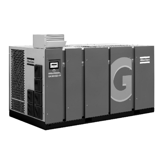
Instruction book General description Introduction General view General view of GA VSD Description of GA VSD compressors GA VSD (Variable Speed Drive) compressors are single-stage, oil-injected screw compressors directly driven by an electric motor. The compressors deliver pulsation-free air. By continuously matching the speed of the drive motor to the air net pressure, the compressor optimizes energy consumption and reduces the operating pressure band. -
Page 14: Air And Oil System
Instruction book Air and oil system Flow diagrams Flow diagram for air-cooled GA VSD compressors (Energy recovery model year 2007) APF192090... - Page 15 Instruction book Flow diagram for air-cooled GA VSD compressors (Energy recovery model year 2014) Drawing Reference Description In parentheses Air outlet Air inlet Condensate drain of the compressor Condensate drain of the dryer APF192090...
- Page 16 Drawing Reference Description Customer's installation Atlas Copco installation For symbols / linestyles refer to 9823 4059 00 R and Atlas Copco standard 1280 K Flow sheet legend 9823 5075 00 * Options Dryer bypass (see instruction 9823 5091 00)* (10)
- Page 17 Instruction book Rear view of air-cooled GA Air flow Air drawn through filter (AF) is compressed in compressor element (E). Compressed air and oil are discharged through check valve (CV) to air receiver/oil separator (AR) where oil is separated from the compressed air. The air is blown through minimum pressure valve (Vp) to air cooler (Ca).
-
Page 18: Cooling And Condensate System
Instruction book In the air receiver (AR) most of the oil is removed from the air centrifugally. Almost all of the remaining oil is removed by the separator element. Cooling and condensate system Condensate drain system Condensate drains of air-cooled GA Automatic condensate drain, compressor Manual condensate drain A condensate trap is installed downstream of the air cooler to prevent condensate from entering the air outlet... -
Page 19: Elektronikon Regulator
Instruction book Elektronikon regulator Elektronikon control system Main functions In general, the Elektronikon regulator has the following functions: • Controlling the motor speed (Variable Speed Drive), reducing the power consumption and pressure band. • Controlling the speed of the fans of the coolers, reducing the power consumption and noise level. •... - Page 20 Instruction book Ref. Designation Load Indirect stop Start (10) Indirect stop offset If the motor is running at minimum speed and the net pressure rises to a value equal to the sum of the programmed pressure set-point and the programmed indirect stop offset, the compressor will stop. When the net pressure drops, the regulator will calculate the optimum moment to restart the compressor to avoid the net pressure decreasing below the pressure set-point (anticipated starting).
-
Page 21: Control Panel
The regulator has a built-in function to automatically restart the compressor if the voltage is restored after voltage failure. This function is deactivated in compressors leaving the factory. If desired, the function can be activated. Consult Atlas Copco. If activated and provided the module was in the automatic operation mode, the compressor will automatically restart if the supply voltage to the module is restored within a programmed time period. -
Page 22: Function Keys
Instruction book Reference Designation Function Tabulator key Key to select the parameter indicated by the horizontal arrow. Only the parameters followed by an arrow pointing to the right can be modified. Function keys Keys to control and program the compressor. Voltage on LED Indicates that the voltage is switched on. -
Page 23: Scroll Keys
“Cancel” To cancel a programmed setting when programming parameters “Delete” To delete compressor start/stop commands “Help” To find the Atlas Copco internet address “Limits” To show limits for a programmable setting “Load” Not used on VSD (Variable Speed Drive) compressors To load the compressor manually “Mainscreen”... -
Page 24: Emergency Stop Button
Instruction book Emergency stop button Control panel Description In case of emergency, press button (S2) to stop the compressor immediately. Using the emergency stop breaks the circuit to: • the variable speed drive unit of the drive motor. • on air-cooled compressors, the variable speed drive unit of the fan motors. •... - Page 25 Instruction book Menu flow for air-cooled GA 132/160 VSD compressors (simplified example) Program Function Main screen Shows in brief the operational status of the compressor. Is the gateway to all functions. “Status Data” Calls up the status of the compressor protection functions (shut-down, shut-down warning and service warning).
-
Page 26: Calling Up Menus
Instruction book Program Function “Counters” Calls up: • running hours • regulator (module) hours • number of motor starts “Test” Display test. “Modify Parameters” Modifying the settings for: • Parameters (e.g. loading and unloading pressures) • Protections (e.g. temperature shut-down level) •... -
Page 27: Main Screen Menu
Instruction book After pressing the “Menu” (F1) key, the option “Status Data” will be followed by a horizontal arrow: • Either press the tabulator key (2) to select this menu, • or use the arrow down key (1) until the desired submenu is followed by a horizontal arrow and then press the tabulator key (2) to select this menu. -
Page 28: Status Data Menu
Instruction book • Messages regarding the compressor operating condition • Just above the function keys (3), the actual functions of these keys Status data menu Warning Before starting any maintenance or repairs, press the stop button (4), wait until the compressor has stopped, press the red emergency stop button and open the isolating switch (customer's installation) to switch off the voltage to the compressor. - Page 29 Instruction book “All Conditions Are OK” “Menu” “Help” A shut-down message exists • In case the compressor is shut down, LED (1) will blink. • In case of a shut-down due to too high a temperature at the outlet of the compressor element: “Element Outlet”...
- Page 30 “Status Data” menu to “Inputs” and press the “Reset” key to reset the service message. • In case the service message was referring to “Plan”: carry out the service actions related to the indicated plans. Reset the timers of the related plans. Contact your Atlas Copco Customer Centre. See Service menu.
-
Page 31: Measured Data Menu
Instruction book 3.10 Measured data menu Control panel Function To call up information regarding the actually measured data and the status of some inputs such as the motor overload protection. Consult the menu flow in section Control programs. Procedure Starting from the Main screen (see Main screen menu): •... -
Page 32: Counters Menu
Instruction book 3.11 Counters menu Control panel Function To call up: • The running hours • The loaded hours • The number of motor starts • The number of hours the regulator (module) has been under tension • The number of load cycles Procedure Starting from the Main screen (see Main screen... -
Page 33: Test Menu
Instruction book 3.12 Test menu Control panel Function To carry out a display test, i.e. to check whether the display and LEDs are still intact. Procedure • Starting from the Main screen (see Main screen menu), press the “Menu” (F1) key. •... -
Page 34: Modifying Compressor/Motor Settings
Instruction book 3.14 Modifying compressor/motor settings Control panel Function To modify a number of settings. Consult the menu flow in section Control programs. Procedure Starting from the Main screen (see Main screen menu): • Press the key “Menu” (F1). • Press the arrow down key (1) until “Modify parameters” is followed by an arrow pointing to the right. •... -
Page 35: Fan Motor Settings
Instruction book “Setpoint 1” 7.0 bar “Setpoint 2” 6.0 bar “Indirect Stop Level” 0.3 bar “Menu” “Modify” The regulator will not accept new values beyond the limitations. It is possible to check the limitations which are valid for the parameter to be modified by selecting “Limits”. -
Page 36: Modifying Parameters
Instruction book “Minimum Speed” 0 “rpm” “Maximum RPM Reduction” 100 “pct” “Menu” “Modify” 3.16 Modifying parameters Function Control panel To modify a number of parameters. Consult the menu flow in section Control programs. Procedure Starting from the Main screen (see Main screen menu): •... -
Page 37: Modifying Protection Settings
Instruction book The regulator will not accept new values beyond the limitations. Press the key “Limits” to check the limitations for the parameter. Consult Programmable settings for the most important settings. 3.17 Modifying protection settings Control panel Function To modify protection settings: •... -
Page 38: Modifying Service Plans
Service plans are to be carried out. Always consult your Atlas Copco Customer Centre in case any timer should be changed. The intervals must not exceed the programmed nominal values. -
Page 39: Programming Clock Function
Instruction book 3.19 Programming clock function Control panel Function To program: • Time-based start/stop commands for the compressor • Time-based change-over commands for the net pressure band Programming start, stop and pressure band commands In this example, the compressor will be programmed as follows: •... - Page 40 Instruction book “Monday” “Tuesday” “Wednesday” “Menu” “Delete” • Use the scroll keys (1) until the day on which a command must be programmed is followed by a horizontal arrow. Press the tabulator key (2); following screen appears: --:-- ---------------------- --:-- ---------------------- --:-- ----------------------...
- Page 41 Instruction book “Clock Function” “Not Activated” “Menu” “Modify” “Delete” • Press the key “Modify”, “Not Activated” starts blinking. • Press the arrow down key (1) “Not Activated” changes to “Activated”. • Press the key “Program”. It is necessary to program the start/stop commands in successive order timewise. Program the commands from Monday till Sunday, e.g.: •...
- Page 42 Instruction book arrow. Press the key “Modify”, the first two digits of the command start blinking. Modify as required using the scroll keys, i.e. in the example above change “18” into “17” using the arrow up key (1). • If necessary, press the tabulator key (2) to go to the next field to be modified, the minutes indication and the start/stop/pressure band indication.
-
Page 43: Modifying Configuration Settings
Instruction book Press the arrow down key and add the last command of the list (in the example above “18:00 Stop Compressor” and press the key “Program”. Deleting a command • Starting from the Main screen, press the key “Menu” (F1), press the arrow down key until the option “Modify Parameters”... - Page 44 Instruction book Function To modify a number of parameters. Consult the menu flow in section Control programs. Procedure Starting from the Main screen (see Main screen menu): • Press the key “Menu” (F1). • Press the arrow down key (1) until “Modify Parameters” is followed by an arrow pointing to the right. •...
-
Page 45: Service Menu
Instruction book 3.21 Service menu Control panel Function • To reset the service plans which are carried out. • To check when the next service plans are to be carried out. • To find out which service plans were carried out previously. Service plans A number of service operations are grouped (called Level A, Level B, etc...). - Page 46 Instruction book Procedure Starting from the Main screen (see Main screen menu): • Press the key “Menu” (F1). • Press the arrow down key (1) until “Service” is followed by a horizontal arrow. • Activate the menu by pressing tabulator key (2). •...
-
Page 47: Saved Data Menu
Instruction book 3.22 Saved data menu Control panel Function To call up some data saved by the regulator. These data are: • Last shut-down data • Last emergency stop data Procedure Starting from the Main screen (see Main screen menu): •... - Page 48 Instruction book Minimum Factory Maximum setting setting setting Proportional band Integration time Minimum motor speed 1500 Maximum rpm reduction Parameters Minimum Factory Maximum setting setting setting Minimum stop time: Permissive start time: Power recovery time (ARAVF) 3600 Restart delay Communication time-out Protections Minimum Factory...
- Page 49 Delay at signal Remark A number of service operations are grouped (Level A, Level B, ...). Each level stands for a number of service operations to be carried out at the programmed intervals. Consult your Atlas Copco Service Centre. APF192090...
- Page 50 To activate the automatic restart function, consult Atlas Copco. Delay at shut- Is the time for which the signal must exist before the compressor is shut down. If it is down signal required to program this setting to another value, consult Atlas Copco. APF192090...
-
Page 51: Installation
Instruction book Installation Dimension drawing Compressor dimensions Dimension drawing of air-cooled Pack VSD compressors APF192090... - Page 52 Instruction book Text on drawing Reference Designation Compressed air outlet Cooling air outlet Compressor air inlet Cooling air inlet Right hand side view Left hand side view Electric cable entry Automatic drain, dryer Rear side view (10) Manual drain (11) Automatic drain (12) Detail X...
-
Page 53: Installation Proposal
Instruction book Installation proposal Compressor room example Compressor room example of GA VSD air-cooled compressor Text on drawing APF192090... - Page 54 Instruction book Reference Designation Minimum free area to be reserved for compressor installation Ventilation proposals Cooling systems Compressor air outlet, if dryer is by-passed Compressor air outlet, Full-Feature compressors Motor ventilation, air outlet Motor ventilation, air inlet Compressor air inlet Cooling air outlet (10) Dryer cooling air outlet...
- Page 55 Instruction book Phase Description Install the compressor on a level floor suitable for taking its weight. For ventilation alternative 1 (indicated as Alt. 1), the minimum distance between the top of the bodywork and the ceiling is 1200 mm (47.2 in). Remove the plastic plug (if provided) from the compressor air outlet pipe and fit the air outlet valve (to be provided by the customer) to the pipe.
-
Page 56: Electric Cable Size And Fuses
The fan capacity should match the compressor fan capacity at a pressure head equal to the pressure drop caused by the cooling air outlet ducts. Consult Atlas Copco. Remove the plastic plugs (if provided) from the condensate outlets and fit the manual condensate drain valve. -
Page 57: Electric Connections
Electric connections General instruction for the electrical installation of VSD compressors • Electrical equipment from Atlas Copco Compressor is designed in accordance with the safety regulations described in IEC60204-1 and CENELEC EN60204. • It is the responsibility of the customer to install the compressor unit according to the safety regulations in order to protect people from electric shocks from direct or indirect contact. - Page 58 Instruction book Atlas Copco strongly recommends that customers do not connect the neutral conductor from the power supply to the compressor unit. The exposed conductive parts of the installation must be earthed locally. (EN 60204-1 par.: 7.2.3) Power distribution systems (TN, TT, IT) According to IEC 60950, there are three main types of power distribution systems: TN, TT and IT.
- Page 59 Instruction book Power system earth Exposed conductive parts Network type TN-C-S (Terra Neutral-Combined-Separate) : In the TN-C-S power distribution system, the neutral and the protective earth functions are combined to some degree in a single conductor, a direct earth to the exposed conductive parts of the installation exists in part. The connection is achieved through the PEN conductor.
- Page 60 Instruction book Power system earth Exposed conductive parts Impedance Ambient conditions The drive must only be used in a heated, indoor and controlled environment. Environmental limits are listed below. Operation Installed for stationary use Air temperature No frost allowed Relative humidity 5 to 95 % No condensation allowed.
- Page 61 Instruction book Electric cabinet Cabinet with VSD (Variable Speed Drive) unit of GA 132/160 VSD APF192090...
- Page 62 Instruction book Electric diagram of GA 132/160 VSD Ref. Designation RFI filter Frequency converter, drive motor Frequency converter, fan motors of air/oil cooler block Frequency converter, compressor motor of dryer F3/5 Circuit breakers, control circuit F17/47 Circuit breakers, condensate circuit Auxiliary relay, motor running indication Contactor, emergency stop Drive motor...
- Page 63 Drive motor of dryer Fan motor of dryer, air-cooled Cable connection for GA 110 VSD, GA 132 VSD and GA 160 VSD Always use cable glands. A plate (1) has to be made by the customer to cover up the hole in the cubicle and to install cable glands.
- Page 64 Instruction book APF192090...
-
Page 65: Quality Of Safety Components
Instruction book Cable section Cable diameter Cable gland size AC number 0698 5140 71 0698 5140 71 11.0 0698 5140 72 12.4 0698 5140 73 13.8 0698 5140 73 Quality of safety components When installing a remote emergency button or a motor contactor, the following B10d values are advised: •... - Page 66 Instruction book Figure A APF192090...
- Page 67 Instruction book Figure B APF192090...
-
Page 68: Installation Instructions For Heavy Duty Filter For Vsd Cubicle
Instruction book Completed assembly of the cubicle fan Installation instructions for heavy duty filter for VSD cubicle Description 1. Remove the original filters (1). Remove the red plates (2). APF192090... - Page 69 Instruction book 2. Place the seals (3) on the back side of the box, then install the box to the cubicle door using rivets. The ordering number for the seals is 1619 5188 00. 3. Install the heavy duty filters as shown below. APF192090...
- Page 70 Instruction book Text on figure: APF192090...
-
Page 71: Installation Instructions For Dryer By-Pass
Instruction book Cooling air flow Compressor side Outside Installation instructions for dryer by-pass Description It is not required to connect a bypass, a blind flange is foreseen ex factory. If by-passing of the dryer is required, connect the compressor to the air net as shown below. The compressed air outlet temperature sensor (G3/8”) and the pressure transducer (1/4”... - Page 72 Instruction book Shut-off valve, air net By-pass valve, compressor By-pass valve, dryer New location for temperature sensor and pressure transducer Pipe towards air net Nipple APF192090...
-
Page 73: Installation Instructions Gsm Alarm
Instruction book Installation instructions GSM alarm Hardware installation Fix the Air contact module (1) to the rail as shown below. Assemble the power supply cable, using: • connector X150.3 (ordering number 1088 0037 64) • two power wires (ordering number 0017 2010 40) •... - Page 74 Instruction book The antenna must be led to the outside of the cubicle. The antenna cable can be led through a present conduit gland (preferably the gland which contains the Electronic drain cables) or a grommet can be used in a closed hole.
- Page 75 Instruction book Software installation For software installation please contact your local Atlas Copco service center. APF192090...
-
Page 76: Pictographs
Instruction book 4.10 Pictographs Explanation of Pictographs Pictographs at other locations Ref. Designation Start Scroll keys Tabulator key Function keys Voltage on Alarm Automatic operation Stop Automatic condensate drain Manual condensate drain Stop the compressor before maintenance or repair Warning: under tension Read Instruction book before starting the compressor Switch off the voltage and depressurise the compressor before maintenance or repair Before connecting the compressor electrically, consult the instruction manual for the motor... - Page 77 Instruction book Ref. Designation Do not mix oil brands APF192090...
-
Page 78: Operating Instructions
Outdoor/altitude operation If the compressor is installed outdoors or if the air inlet temperature can be below freezing point, precautions must be taken. In this case, and also if operating at high altitude, consult Atlas Copco. Moving/lifting The compressor can be moved by a lift truck using the slots in the frame. Make sure that the forks protrude from the other side of the frame. - Page 79 If the rotation direction is wrong, press the emergency stop button, switch off the voltage and reverse two incoming electric lines. If the rotation direction of the fan motor is wrong, consult your Atlas Copco customer centre. Run the compressor for a few minutes and check that it is operating normally.
-
Page 80: Before Starting
Instruction book Before starting Warning Step Action The operator must apply all relevant safety precautions. See the section Safety precautions. Switch off your mobile phone when in the vicinity of a GA VSD compressor which is under tension. Procedure Step Action Switch on the voltage. -
Page 81: During Operation
Instruction book Step Action Press start button (1). The compressor starts running and automatic operation LED (3) lights up. During operation Description When automatic operation LED (3) is lit, the Elektronikon regulator is automatically controlling the compressor: the speed will continuously vary to match the air delivery to the air consumption, and the compressor will start and stop whenever necessary. - Page 82 Example of the main menu “Status data” “Measured Data” “Counters” “Mainscreen” Example of the main display Example of Main screen of GA 110 VSD up to GA 160 VSD compressors “Compressor Outlet” 7.5 bar “Compressor Speed” 2100 rpm “Menu” APF192090...
-
Page 83: Stopping
Action Press stop button (1): the compressor will stop and LED (2) will go out. To stop the GA 110 VSD up to GA 160 VSD compressor in the event of an emergency, press the emergency stop button (S2). Close air outlet valve. -
Page 84: Use Of Air Receiver
Instruction book Use of air receiver Instructions Step Action This equipment can contain pressurised air and oil; be aware of its potential danger if used improperly. This equipment must only be used as compressed air/oil separator and must be operated within the specified limits. -
Page 85: Maintenance
Instruction book Maintenance Preventive maintenance schedule Warning Before carrying out any maintenance, repair work or adjustment, proceed as follows: • Stop the compressor. Press emergency stop button (S2). • • Close the air outlet valve and open the manual condensate drain valves. •... -
Page 86: Motors
Elektronikon regulator. When a level is reached, a message will appear on the screen. After carrying out all service actions, the interval timers must be reset using the “Reset” key in the “Service” menu. Consult your Atlas Copco Service Centre. Motors Warning Stop the compressor and switch off the voltage. -
Page 87: Oil Specifications
Oil specifications Atlas Copco Roto-Xtend Duty Fluid Atlas Copco Roto-Xtend Duty Fluid is a high-quality synthetic lubricant for oil-injected scroll and screw compressors which keeps the compressor in excellent condition. Roto-Xtend Duty Fluid can be used for compressors operating at ambient temperatures between 0 ˚C (32 ˚F) and 46 ˚C (115 ˚F) (see section Service kits). - Page 88 Instruction book Procedure 1. Run the compressor until warm. Stop the compressor, close the air outlet valve and switch off the voltage. Wait a few minutes and depressurize by unscrewing the vent plug on top of the air receiver to permit any pressure in the system to escape.
- Page 89 Instruction book 1. Take off the side panels of the compressor and remove the stays. 2. Open the cooler compartment and disconnect the cooler inlet pipe (1). 3. Disconnect the cooler outlet pipe (4) and roll out the oil cooler (2). 4.
- Page 90 Instruction book Draining the compressor element, oil filter housing and oil stop valve 1. Remove the drain plug (3) to drain the oil stop valve. 2. Remove the drain plug of the flexible to drain the oil from the gearbox. 3.
-
Page 91: Storage After Installation
Service kits General Service kits comprise all parts needed for servicing components and offer the benefits of genuine Atlas Copco parts while keeping the maintenance budget low. All service kits are indicated in the relevant Parts Lists. Atlas Copco Roto-Xtend Duty Fluid Roto-Xtend Duty Fluid can be ordered in the following quantities: •... - Page 92 Instruction book Oil specifications. APF192090...
-
Page 93: Dd Filter
Instruction book DD filter Maintenance When maintaining the filter, keep in mind the following: • On filters with manual drain valve, open the latter at regular intervals to evacuate collected dust or liquid • Change the filter element yearly or when the pressure drop reaches approx. 0.35 bar •... -
Page 94: Filter Disposal
Instruction book 4. Discard the old filter element. 5. Remove the O-ring from the bowl and clean the bowl with isopropanol. Cleaning cloths of Kimtech are recommended. Position a new O-ring on the bowl. 6. Open the sealed bag at the topcap side of the filter cartridge. 7. -
Page 95: Integrated Dryer
Instruction book Integrated dryer Condensate drain system Description The condensate enters the Electronic Water Drain (EWD) via inlet (1) and accumulates in the water separator of the heat exchanger and in collector (2). A capacitive sensor (3) continuously measures the liquid level. As soon as the collector is filled up to a certain level, a drain delay timer is started. -
Page 96: Maintenance Instructions
Instruction book Testing the Electronic water drain Control panel, EWD Briefly press the TEST button and check that the valve opens for condensate discharge. Checking the alarm signal • Press and hold the test button for at least 1 minute. •... -
Page 97: Problem Solving
Instruction book Warranty and product liability Use only Atlas Copco authorized genuine parts. Any damage or malfunction caused by the use of unauthorized parts is not covered by Warranty or Product Liability. General The following remarks should be kept in mind: •... -
Page 98: Adjustments And Servicing Procedures
Instruction book Adjustments and servicing procedures Air filters Warning Stop the compressor, close the air outlet valve, press the emergency stop button and switch off the voltage. The operator must apply all relevant Safety precautions. Control panel of MkIV regulator Control panel of MkIV regulator APF192090... - Page 99 Instruction book Position of air filter Procedure Step Action Remove panel (4) from the compressor. Remove the filter element. Fit the new filter element. Reinstall panel (4) Reset the message and service timer: Press the “Menu” key (3). • Press key (1) until “Service” is followed by an arrow pointing to the right. Activate the •...
-
Page 100: Coolers
Instruction book Coolers Checking the coolers for cleanliness on air-cooled compressors Activate the "Cleanlinesstest" option in the Elektronikon regulator as follows: • Starting from the main screen, press the "Menu" key. • Press the arrow down key (1) until "Test" is followed by a horizontal arrow. •... - Page 101 Clean the coolers with an air jet in the reverse direction to normal flow. Use low pressure air; if necessary, the pressure may be increased up to 6 bar (e) (87 psig) If it is necessary to clean the coolers with a cleaning agent, consult Atlas Copco. Close the inside doors.
-
Page 102: Safety Valve
No adjustments are allowed. Testing The valve can be tested on a separate compressed air line. Consult the Atlas Copco Customer Centre if the valve does not open at the correct pressure (see the section Settings of safety valve). APF192090... -
Page 103: Problem Solving
Instruction book Problem solving 10.1 Problem solving Warning Before carrying out any maintenance, repair work or adjustment, stop the compressor, press the emergency stop button and switch off the voltage. Close the air outlet valve and open the manual condensate drain valves. Open and lock the isolating switch. - Page 104 “Reset” key (2); the message “All protection functions are OK” will appear, after which the compressor can be restarted. Excessive oil consumption Have the compressor inspected by the Atlas Copco Customer Centre. Condition Fault Remedy...
-
Page 105: Technical Data
Instruction book Technical data 11.1 Readings on display General Control panel Reference Units Reading Outlet pressure bar(e) Depends on pressure set-point Speed Varies (controlled by regulator) Maximum working pressure bar(e) Compressor data. At pressure set-point Reference Units 4 bar(e) 7 bar(e) 9.5 bar(e) 13.5 bar(e) Dp of air filter, approx. -
Page 106: Reference Conditions
Instruction book 11.2 Reference conditions Reference conditions Absolute inlet pressure bar(a) Relative air humidity Air inlet temperature ˚C Nominal working pressure See Compressor data Cooling medium inlet temperature ˚C 11.3 Limits Limits Maximum air inlet/ambient temperature, GA 110 VSD up to GA ˚C 160 VSD Minimum air inlet/ambient temperature... -
Page 107: Compressor Data
TT/TN CSA/UL CSA/UL 2.,5 CSA/UL 11.6 Compressor data Data for GA 125 psi (8.6 bar) 60 Hz compressors Units GA 160 VSD Maximum working pressure, GA Pack bar(e) Nominal working pressure bar(e) Motor shaft speed for: Pack compressors r/min 2779... -
Page 108: Pressure Equipment Directives
Pressure equipment directives Category IV Product: • GA 160 VSD This machine is a pressure assembly of cat. IV according to 97/23/EC. Parts of article 3.3 of 97/23/EC are subject to good engineering practice. Parts of category I according to 97/23/EC are integrated into the machine and fall under the exclusion of article I, section 3.6. - Page 109 Instruction book Reference Description Cover serial number here Data plate here Minimum wall thickness after corrosion of the vessel 5.5mm (0.216 in) Minimum wall thickness after corrosion of the cover 8 mm (0.315 in) Lifetime infinite according to AD2000-S1 § 4.2.2. Delta p 7.5 bar (108.8 psi) Casting factor cover...
-
Page 110: Documentation
Instruction book Documentation Declaration of conformity Typical example of a Declaration of Conformity document APF192090... - Page 112 Not for the sake of technology, but for the sake of our customer’s bottom line and peace-of-mind. That is how Atlas Copco will strive to remain the first choice, to succeed in attracting new business and to maintain our position as the industry leader.
Need help?
Do you have a question about the GA 160 VSD and is the answer not in the manual?
Questions and answers