Table of Contents
Advertisement
Quick Links
for BMW - MINI vehicles with
Business/Professional CIC-E and CIC-F series
navigation systems or radios with colour display
and 4pin HSD LVDS monitor plug
Video-inserter with 2 video + RGB + rear-view camera input
Product features
Video-inserter for factory-infotainment monitors
2 video-inputs for after-market devices (e.g. DVD-Player, DVB-T tuner, ...)
Built-in audio-switch (no audio-insertion)
Rear-view camera video-input
Automatic switching to rear-view camera input on engagement of reverse gear
Picture-in-picture mode combining after-market rear-view and front camera
picture(s) with factory parking sensor graphic
Activitable parking guide lines for rear-view camera
RGB-input for after-market navigation
Video-in-motion (ONLY for connected video-sources)
Compatible with factory rear-view camera
AV-inputs PAL/NTSC compatible
Ultra-wide picture mode 24:9 (only with ultra-wide screens 8.8" and 10.2")
Version 24.01.2013
v.LiNK Video-inserter
CI-VL2-CIC-F
Advertisement
Table of Contents

Related Manuals for Car-Interface v.LiNK CI-VL2-CIC-F


Summary of Contents for Car-Interface v.LiNK CI-VL2-CIC-F
- Page 1 v.LiNK Video-inserter CI-VL2-CIC-F for BMW - MINI vehicles with Business/Professional CIC-E and CIC-F series navigation systems or radios with colour display and 4pin HSD LVDS monitor plug Video-inserter with 2 video + RGB + rear-view camera input Product features Video-inserter for factory-infotainment monitors ...
-
Page 2: Table Of Contents
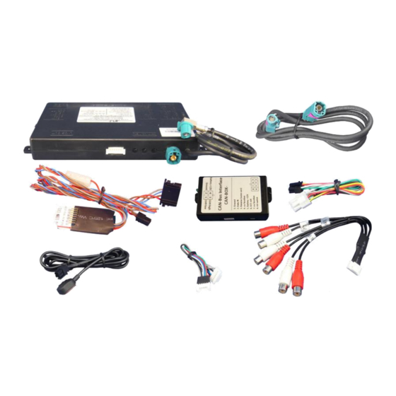
Contents 1. Prior to installation 1.1. Delivery contents 1.2. Checking the compatibility of vehicle and accessories 1.3. Dip-switch settings 1.3.1. Vehicle selection (dip 6-8) 1.3.1.1. Video signal selection after-market navigation (Dip 4) 1.3.2. Enabling the interface’s video inputs (dip 1-3) 1.3.3. -
Page 3: Prior To Installation
Legal Information By law, watching moving pictures while driving is prohibited, the driver must not be distracted. We do not accept any liability for material damage or personal injury resulting, directly or indirectly, from installation or operation of this product. This product should only be used while standing or to display fixed menus or rear-view-camera video when the vehicle is moving, for example the MP3 menu for DVD upgrades. -
Page 4: Checking The Compatibility Of Vehicle And Accessories
1.2. Checking the compatibility of vehicle and accessories Requirements Vehicle BMW 1series (E87), 3series (E90/91/92/93), 5series (E60/61/F10/F11), 6series (E63/64/F12/F13), 7series (F01/F02), GT5 (F07), X1 (E84), X3 (F25), X5 (E70), X6 (E71), Z4 (E89)), Mini from about 09/2010 Head-unit/monitor Business/Professional CIC-E and CIC-F navigation systems or radios with colour display with 4pin HSD LVDS monitor plug Limitations... -
Page 5: Enabling The Interface's Video Inputs (Dip 1-3)
1.3.3. Enabling the interface’s video inputs (dip 1-3) Only the enabled video inputs can be accessed when switching through the video sources. It is recommended to enable only the required inputs for the disabled will be skipped when switching through the video interfaces inputs. Video-input ON (down) OFF (up) -
Page 6: Connection Schema
2.2. Connection schema Version 24.01.2013 CI-VL2-CIC-F... -
Page 7: Connecting Video-Interface And Can-Box
2.3. Connecting video-interface and CAN-box Connect black female 4pin Micro-Fit connector of the 4pin cable to the male 4pin Micro-Fit connector of the CAN-box. Note: Check LEDs on CAN-box after reconnecting the battery, one must be on. Connect white female 6pin Molex connector of the 6pin to 8pin cable to the male 6pin Molex connector of the video-interface. -
Page 8: Connection To The Factory Monitor
2.4. Connections to the factory monitor Remove factory monitor. Remove female 4pin HSD LVDS connector from the rear of the factory monitor and connect it to the male 4pin HSD LVDS connector of the video-interface. Connect female 4pin connector of the 4pin HSD LVDS cable to the male 4pin HSD LVDS connector of the factory monitor. -
Page 9: Video-Sources To In1 And In2
2.5.1. Video-sources to IN1 and IN2 Connect video RCA of the AV-source 1 to the female RCA connector IN1 of the video- interface. Connect video RCA of the AV-source 2 to the female RCA connector IN2 of the video- interface. 2.5.2. - Page 10 Note: If only one AV-source shall be connected, it is possible to connect the video output of the AV-source to video IN1 of the video-interface and the audio output of the AV-source direct to the audio-insertion. Connect female 8pin connector of the audio cable to male 8pin connector of the video-interface.
-
Page 11: After-Market Rear-View Camera
2.5.3. After-market rear-view camera Connect the video-RCA of the after-market rear-view camera to the female RCA port of the video-interface. If the Can-bus does not work while connecting an after-market rear-view camera, cut the green cable of the 6pin to 8pin cable at the black 8pin connector and connect it to the reverse gear light (+12V). -
Page 12: After-Market Navigation
2.5.4. After-Market navigation Connect female 8pin connector of the RGB cable to the male 8pin connector of the video-interface. The loose grey wires have no function and have to be isolated. Connect male 6pin connector of the RGB cable to the after-Market navigation. 2.6. -
Page 13: Picture Settings
2.7. Picture settings After installing the sources the picture settings can be changed using a pen on the buttons of the video interface. Press the MENU button to open settings menu on the OSD and to switch to the next setting. UP and DOWN change the corresponding values. The buttons are embedded in the housing to avoid accidental changes during or after installation. -
Page 14: Interface Operation
3. Interface operation 3.1. By iDrive-buttons Some of the iDrive-buttons can be used to execute interface functions. Long press NAV-button (MAP-button) to switch the video source. Each repetition will switch to the next enabled input. If all inputs are enabled the order is: ... -
Page 15: Specifications
4. Specifications BATT/ACC range 7V ~ 25V Stand-by power drain <10mA Power 0.2A @12V Power consumption 2.4W Video input 0.7V~1V Video input formats PAL/NTSC RGB-video amplitude 0.7V with 75 Ohm impedance Temperature range -40°C to +85°C Weight 195g Dimensions (box only) B x H x T 182 x 24 x 100 mm 5.
Need help?
Do you have a question about the v.LiNK CI-VL2-CIC-F and is the answer not in the manual?
Questions and answers