Table of Contents
Advertisement
Quick Links
MIB High/Standard infotainment systems
with 7"/8" or 5.8" monitors
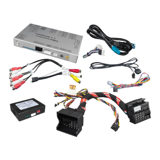
Video-inserter with 2 video + RGB + rear-view camera input and CAN control
Product features
Video-inserter for factory-infotainment monitors
2 video-inputs for after-market devices (e.g. DVD-Player, DVB-T tuner, ...)
Built-in audio-switch (no audio-insertion)
Rear-view camera video-input
Automatic switching to rear-view camera input on engagement of reverse gear
Activitable parking guide lines for rear-view camera
RGB-input for after-market navigation
Video-in-motion (ONLY for connected video-sources)
Compatible with factory rear-view camera
AV-inputs PAL/NTSC compatible
Version 23.11.2015
v.LiNK Video-inserter
CI-VL2-MIB-3
for VAG vehicles with
Advertisement
Table of Contents

Related Manuals for Car-Interface CI-VL2-MIB-3


Summary of Contents for Car-Interface CI-VL2-MIB-3
- Page 1 Video-inserter CI-VL2-MIB-3 for VAG vehicles with MIB High/Standard infotainment systems with 7”/8” or 5.8” monitors Video-inserter with 2 video + RGB + rear-view camera input and CAN control Product features Video-inserter for factory-infotainment monitors 2 video-inputs for after-market devices (e.g. DVD-Player, DVB-T tuner, …) ...
-
Page 2: Table Of Contents
Case 2: CAN-box does not detect reverse gear 2.5.4.3. Video signal connection 2.6. Connecting video-interface and keypad 2.7. Picture settings and guide lines 3. Interface operation 3.1. By factory infotainment button 3.2. By keypad 4. Specifications 5. Frequently asked questions Version 23.11.2015 CI-VL2-MIB-3... -
Page 3: Prior To Installation
Technical knowledge is necessary for installation. The place of installation must be free of moisture and away from heat sources. 1.1. Delivery contents Take down the serial number of the interface and store this manual for support purposes: ____________________ Version 23.11.2015 CI-VL2-MIB-3... -
Page 4: Checking The Compatibility Of Vehicle And Accessories
To extend the switch- back additional electronics is required. 1.3. Boxes and connectors 1.3.1. CAN-bus box The CAN-bus box reads digital signals from the CAN-bus and converts them for the video- interface. Version 23.11.2015 CI-VL2-MIB-3... -
Page 5: Video-Interface
Only the enabled video inputs can be accessed when switching through the interface’s video sources. It is recommended to enable only the required inputs for the disabled will be skipped when switching through the video interfaces inputs. Version 23.11.2015 CI-VL2-MIB-3... -
Page 6: Rgb-Video Input Signal Selection For After-Market Navigation (Dip 4)
4 options, retry and disconnected the 6pin power plug of the video- box between every change of the dip setting. Empirical value: Vehicle/ Navigation Dip 7 Dip 8 7”/8“-monitor 5.8”- monitor Version 23.11.2015 CI-VL2-MIB-3... -
Page 7: Dip-Switch Settings Of The Can-Box
If power source is not taken directly from the battery, the connection has to be checked for being start-up proven and permanent. 2.1. Place of installation The interface is installed on the backside of the head-unit. Version 23.11.2015 CI-VL2-MIB-3... -
Page 8: Connection Schema
2.2. Connection schema Version 23.11.2015 CI-VL2-MIB-3... -
Page 9: Connecting Video-Interface And Can-Box
Note: Check LEDs on video-interface after reconnecting the battery, one must be on. Note: No liability for vehicle wire colours and pin definition! Possible changes by the vehicle manufacturer. The given information must be verified by the installer. Version 23.11.2015 CI-VL2-MIB-3... -
Page 10: Connection To The Head-Unit
Remove the female Quadlock connector of the vehicle harness from the rear of the head-unit and connect it to the male Quadlock connector of Quadlock harness. Connect female Quadlock connector of Quadlock harness to the male Quadlock connector of the head-unit. Version 23.11.2015 CI-VL2-MIB-3... -
Page 11: Connecting Peripheral Devices
Connect male 6pin connector of the RGB cable to the after-Market navigation. If connecting the after market navigation NAV-FN900D the factory touch-screen can be used. Please do the following step, too: Connect female 8pin connector of 6pin to 8pin cable to 8pin connector (Ctrl) of the video-interface. Version 23.11.2015 CI-VL2-MIB-3... -
Page 12: Video-Sources To Av1 And Av2
Connect video RCA of the AV-source 1 to the female RCA connector Video 1 of the video cable. Connect video RCA of the AV-source 2 to the female RCA connector Video 2 of the video cable. Version 23.11.2015 CI-VL2-MIB-3... -
Page 13: Audio-Switch And Audio-Insertion
RCA port AV-Out of the audio cable. Connect the audio-RCA of the AV-source 1 to the female RCA port AV1 of the audio cable. Connect the audio-RCA of the AV-source 2 to the female RCA port AV2 of the audio cable. Version 23.11.2015 CI-VL2-MIB-3... -
Page 14: After-Market Rear-View Camera
CAM while reverse gear is engaged. Additionally, the +12V (max. 500mA) power supply for the rear-view camera can be taken from the green wire of the 6pin to 8pin cable. Version 23.11.2015 CI-VL2-MIB-3... -
Page 15: Case 2: Can-Box Does Not Detect Reverse Gear
Connect reverse gear light signal/power to coil (85) and ground to coil (86) of relais. Connect rear-view camera power and green wire (video interface side) of 6pin to 8pin cable to output (87) of relay. Connect permanent battery power to input (30) of relay. Version 23.11.2015 CI-VL2-MIB-3... -
Page 16: Video Signal Connection
CAM. Note: Picture settings for CAM input must be done in AV2. 2.7. Connecting video-interface and keypad Connect the female 4pin connector of the keypad to the male 4pin connector of the video-interface. Version 23.11.2015 CI-VL2-MIB-3... -
Page 17: Picture Settings And Guide Lines
The following settings are available: Contrast Brightness Saturation Position H (horizontal) Position V (vertical) Guide-CNTRL (guide lines ON/OFF) Note: If the CAN-box does not support the very vehicle, the guide-lines cannot be used. Version 23.11.2015 CI-VL2-MIB-3... -
Page 18: Interface Operation
Power consumption 28.4W Video input 0.7V~1V Video input formats PAL/NTSC RGB-video amplitude 0.7V with 75 Ohm impedance Temperature range -40°C to +85°C Weight 368g Dimensions (box only) W x H x D 154 x 22 x 92 mm Version 23.11.2015 CI-VL2-MIB-3... -
Page 19: Frequently Asked Questions
Camera is being tested under Camera input picture fluorescent light which shines Test camera under natural light outside the garage. flickers. directly into the camera. Camera input picture is Protection sticker not Remove protection sticker. bluish. removed from camera lens. Version 23.11.2015 CI-VL2-MIB-3... - Page 20 Cut the grey wire of 6pin to 8pin and isolate both Interface switches compatibility to vehicle is ends. If problem still occurs, additionally cut the white video-sources by itself. limited. wire of 6pin to 8pin cable and isolate both ends. 10R-03 5384 Made in China Version 23.11.2015 CI-VL2-MIB-3...
Need help?
Do you have a question about the CI-VL2-MIB-3 and is the answer not in the manual?
Questions and answers