
Related Manuals for Car-Interface CI-VL2-CCC


Summary of Contents for Car-Interface CI-VL2-CCC
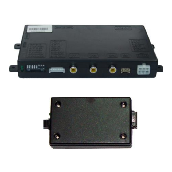
- Page 1 Video-inserter CI-VL2-CCC BMW-Mini monitors with 10pin LVDS connector Video-inserter with 2 video + RGB + rear-view camera input and CAN control Version 28.07.2015...
-
Page 2: Table Of Contents
Changes of the vehicle software can cause malfunctions of the interface. We offer free software-updates for interfaces for one year after purchase. To receive a free update, the interface must be sent in at own cost. Labor cost for and other expenses involved with the software-updates will not be refunded. Version 28.07.2015 CI-VL2-CCC... -
Page 3: Prior To Installation
Technical knowledge is necessary for installation. The place of installation must be free of moisture and away from heat sources. 1.1. Delivery contents Take down the serial number of the interface and store this manual for support purposes: ____________________ Version 28.07.2015 CI-VL2-CCC... -
Page 4: Checking The Compatibility Of Vehicle And Accessories
Choose the vehicle/navigation/monitor the interface is to be installed to and set dip 6 through 8 according to the below table. Vehicle/Navigation Dip 6 Dip 7 Dip 8 BMW CCC with 8.8” ultra-wide monitor BMW CIC with 6.5” monitor Version 28.07.2015 CI-VL2-CCC... -
Page 5: Enabling The Interface's Video Inputs (Dip 1-3)
If power source is not taken directly from the battery, the connection has to be checked for being start-up proven and permanent. 2.1. Place of installation The interface is installed on the backside of the vehicle’s monitor. Version 28.07.2015 CI-VL2-CCC... -
Page 6: Connections
- CAN high Pin 3 (blue) - CAN high CAN wires are twisted. No liability for vehicle wire colors and pin definition! Possible changes by the vehicle manufacturer. The given information must be verified by the installer. Version 28.07.2015 CI-VL2-CCC... -
Page 7: Installation Procedure - Function Check
Press the MENU button to open settings menu on the OSD and to switch to the next setting. UP and DOWN change the corresponding values. The buttons are embedded in the housing to avoid accidental changes during or after installation. Version 28.07.2015 CI-VL2-CCC... -
Page 8: Audio Insertion
Definition Audio input signal R/L of source IN2 Audio input signal R/L of source IN1 Audio output signal L/R of factory audio AUX, AUX-110, Dension Gateway 500 or FM- modulator Ground No function Audio-switch- port Audio-cable Video-interface Version 28.07.2015 CI-VL2-CCC... -
Page 9: Interface Operation
Press keypad – video input switching, like press knob to the left, see chapter 3.1. 4. Specifications BATT/ACC range 7V ~ 25V Power 0.3A @12V Video input 0.7V~1V Video input formats PAL/NTSC Weight 195g Dimensions (box only) B x H x T 182 x 24 x 100 mm Version 28.07.2015 CI-VL2-CCC... - Page 10 Camera is being tested under Camera input picture fluorescent light which shines Test camera under natural light outside the garage. flickers. directly into the camera. Camera input picture is Protection sticker not Remove protection sticker. bluish. removed from camera lens. Version 28.07.2015 CI-VL2-CCC...
- Page 11 Cut the grey wire of 6pin to 8pin and isolate both Interface switches compatibility to vehicle is ends. If problem still occurs, additionally cut the white video-sources by itself. limited. wire of 6pin to 8pin cable and isolate both ends. 10R-03 5384 Made in China Version 28.07.2015 CI-VL2-CCC...
Need help?
Do you have a question about the CI-VL2-CCC and is the answer not in the manual?
Questions and answers