Table of Contents
Advertisement
Quick Links
Compatible with Mercedes Benz vehicles
with Comand Online NTG5/NTG5.1
with 4pin HSD LVDS connector on the monitor
Video-inserter with 2 video + RGB + rear-view camera input and CAN control
Product features
Video-inserter for factory infotainment monitors
2 CVBS video-inputs for after-market devices (e.g. DVD-Player, DVB-T tuner, ...)
Rear-view camera video-input
Automatic switching to rear-view camera input on engagement of reverse gear
Activatable parking guide lines for rear-view camera
Video-in-motion (ONLY for connected video-sources)
Compatible with factory rear-view camera
AV-inputs PAL/NTSC compatible
Version 04.05.2017
v.LiNK Video-inserter
CI-VL3-MBN51
Audio20 CD NTG5/NTG5.1
Audio20 USB NTG5/NTG5.1
Advertisement
Table of Contents

Related Manuals for Car-Interface CI-VL3-MBN51


Summary of Contents for Car-Interface CI-VL3-MBN51
- Page 1 Video-inserter CI-VL3-MBN51 Compatible with Mercedes Benz vehicles with Comand Online NTG5/NTG5.1 Audio20 CD NTG5/NTG5.1 Audio20 USB NTG5/NTG5.1 with 4pin HSD LVDS connector on the monitor Video-inserter with 2 video + RGB + rear-view camera input and CAN control Product features ...
-
Page 2: Table Of Contents
Case 2: CAN-box does not detect reverse gear 2.5.3.3. Video signal connection 2.6. Connecting video-interface and keypad 2.7. Picture settings and guide lines 3. Interface operation 3.1. By Comand-buttons 3.2. By keypad 4. Specifications 5. FAQ – Trouble shooting Version 04.05.2017 CI-VL3-MBN51... -
Page 3: Prior To Installation
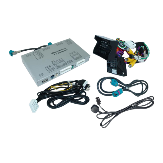
Read the manual prior to installation. Technical knowledge is necessary for installation. The place of installation must be free of moisture and away from heat sources. 1.1. Delivery contents Take down the serial number of the interface and store this manual for support purposes: ____________________ Version 04.05.2017 CI-VL3-MBN51... -
Page 4: Checking The Compatibility Of Vehicle And Accessories
Video sources NTSC video sources compatible only. Factory rear-view camera Automatically switching-back from inserted video to factory rear-view camera is only possible while the reverse gear is engaged. To delay the switch-back, an additional electronic part is required. Version 04.05.2017 CI-VL3-MBN51... -
Page 5: Connectors Video-Interface
RGB-input resolution 800x480 1080p H+V sync Rear-view cam type after-market factory or none No function set to OFF No function set to OFF Monitor selection 7” monitor 8.4” HD monitor See following chapters for detailed information. Version 04.05.2017 CI-VL3-MBN51... -
Page 6: Enabling The Interface's Video Inputs (Dip 1-3)
The Interface needs a permanent power supply! If power isn’t directly taken from the battery, the connection’s power has to be checked for being start-up proven and permanent. 2.1. Place of installation: The interface is installed on the backside of the head-unit. Version 04.05.2017 CI-VL3-MBN51... -
Page 7: Connection Schema
Connection schema Version 04.05.2017 CI-VL3-MBN51... -
Page 8: Connection To The Head-Unit - Lvds
Connect the waterblue-coloured female 4pin HSD LVDS connector of the 4pin HSD LVDS cable to the blue male 4pin HSD LVDS connector of the head-unit. Note: Depending on place of installation and mounting space, the included 4pin HSD extension-cable (CAB-HSD-ML100) can be used Version 04.05.2017 CI-VL3-MBN51... -
Page 9: Connection To The Head-Unit - Quadlock
Remove the female Quadlock connector of the vehicle harness from the rear of the head-unit and connect it to the male Quadlock connector of the Quadlock cable. Connect the female Quadlock connector of Quadlock harness to the male Quadlock connector of the head-unit. Version 04.05.2017 CI-VL3-MBN51... -
Page 10: Connecting Peripheral Devices
Connect the video RCA of the AV-source 1 to the female RCA connector “VideoIN1” of the video cable. Connect the video RCA of the AV-source 2 to the female RCA connector “Video -IN2” of the video cable. Version 04.05.2017 CI-VL3-MBN51... -
Page 11: Audio-Switch And Audio-Insertion
Connect the audio-RCA of the AV-source 1 and the AV source 2 to the female RCA port “AUDIO-IN1” and “AUDIO-IN2” of the audio switch. Connect the audio-RCA of the factory-audio-AUX-input or the FM-modulator to the female RCA port “AUDIO-OUT” of the audio switch. Version 04.05.2017 CI-VL3-MBN51... -
Page 12: After-Market Rear-View Camera
The 12 V power supply for the rear-view camera (max 3A) has to be taken from the green wire of the 20pin cable to avoid an unnecessary permanent power supply to the camera electronic. For the operation, both green cables have to stay connected Version 04.05.2017 CI-VL3-MBN51... - Page 13 (86) of the relay. Connect the output connector (87) of the relay to the rear-view camera’s power- cable, like you did it to the green “Reverse-IN” cable before. Connect permanent power / 12V to the relay’s input connector (30). Version 04.05.2017 CI-VL3-MBN51...
-
Page 14: Video Signal Connection
Video signal connection for the rear-view camera Connect the video-RCA of the after-market rear-view camera to the female RCA port “Camera-IN” of the video-cable. Note: The picture settings for “Camera-IN” input have to be done in AV2. Version 04.05.2017 CI-VL3-MBN51... -
Page 15: Connecting Video-Interface And Keypad
2.6. Connecting video-interface and keypad Connect the keypad’s female 4pin connector to the video-interface’s male 4pin connector. Version 04.05.2017 CI-VL3-MBN51... -
Page 16: Picture Settings And Guide Lines
IR-AV2 (out of function) Guide-lines left Guide-lines right Guide lines (ON/OFF) Note: If the CAN-box does not support the vehicle, the guide-lines cannot be used. If supported and activated, the guide-lines also show the steering wheel position dependant driving path. Version 04.05.2017 CI-VL3-MBN51... -
Page 17: Interface Operation
Switchover by vehicle buttons isn’t possible in all vehicles. In some vehicles the external keypad has to be used. 3.2. By keypad Alternatively or additionally to the factory infotainment buttons, the interface’s enabled inputs can also be switched by the external keypad. Version 04.05.2017 CI-VL3-MBN51... -
Page 18: Specifications
Power 0.3A @12V Video input 0.7V – 1V Video input formats PAL/NTSC RGB-video amplitude 0.7V with 75 Ohm impedance Temperature range -40°C to +85°C Dimensions Video-Box 158 x 23 x 91 mm (W x H x D) Version 04.05.2017 CI-VL3-MBN51... -
Page 19: Faq - Trouble Shooting
Camera is being tested under Camera input picture fluorescent light which shines Test camera under natural light outside the garage. flickers. directly into the camera. Camera input picture is Protection sticker not Remove protection sticker. bluish. removed from camera lens. Version 04.05.2017 CI-VL3-MBN51... - Page 20 Cut the grey wire of 6pin to 8pin and isolate both Interface switches compatibility to vehicle is ends. If problem still occurs, additionally cut the white video-sources by itself. limited. wire of 6pin to 8pin cable and isolate both ends. 10R-03 5384 Made in China Version 04.05.2017 CI-VL3-MBN51...
Need help?
Do you have a question about the CI-VL3-MBN51 and is the answer not in the manual?
Questions and answers