Table of Contents
Advertisement
Quick Links
v.LiNK Video-inserter and navigation
CI-VL2-PC-HSD and CI-NAL-PC-HSD
Compatible with Citroen and Peugeot vehicles
with SMEG or SMEG+ navigation
with 4pin HSD LVDS connector on the monitor
VL2-PC-HSD: Video-inserter with 2 video + RGB + rear-view camera input and
NAL-PC-HSD: Video-inserter with integrated navigation +2 video + rear-view
Product features
Video-inserter for factory-infotainment monitors
2 CVBS video-inputs for after-market devices (e.g. DVD-Player, DVB-T tuner, ...)
Built-in audio-switch (no audio-insertion)
Rear-view camera CVBS video-input
Automatic switching to rear-view camera input on engagement of reverse gear
Activatable parking guide lines for rear-view camera (not for all vehicles)
RGB-input for after-market navigation (VL2 only)
Video-in-motion (ONLY for connected video-sources)
Compatible with factory rear-view camera
AV-inputs PAL/NTSC compatible
Version 07.09.2017
CAN control
camera input and CAN control
Advertisement
Table of Contents

Related Manuals for Car-Interface v.LiNK CI-VL2-PC-HSD


Summary of Contents for Car-Interface v.LiNK CI-VL2-PC-HSD
- Page 1 v.LiNK Video-inserter and navigation CI-VL2-PC-HSD and CI-NAL-PC-HSD Compatible with Citroen and Peugeot vehicles with SMEG or SMEG+ navigation with 4pin HSD LVDS connector on the monitor VL2-PC-HSD: Video-inserter with 2 video + RGB + rear-view camera input and CAN control NAL-PC-HSD: Video-inserter with integrated navigation +2 video + rear-view camera input and CAN control Product features...
-
Page 2: Table Of Contents
Contents Prior to installation 1.1. Delivery contents 1.2. Checking the compatibility of vehicle and accessories 1.3. Boxes and connectors 1.3.1. CAN-bus box 1.3.2. Video-interface 1.3.2.1. Dip-switch settings 1.3.2.2. Enabling the interface’s video inputs (dip 1-3) 1.3.2.3. RGB-video input signal selection for after-market navigation (Dip 4) 1.3.2.4. -
Page 3: Prior To Installation
Legal Information By law, watching moving pictures while driving is prohibited, the driver must not be distracted. We do not accept any liability for material damage or personal injury resulting, directly or indirectly, from installation or operation of this product. This product should only be used while standing or to display fixed menus or rear-view-camera video when the vehicle is moving, for example the MP3 menu for DVD upgrades. -
Page 4: Checking The Compatibility Of Vehicle And Accessories
1.2. Checking the compatibility of vehicle and accessories Requirements Vehicle Citroen and Peugeot Head-unit/monitor Citroen SMEG+, Peugeot SMEG and SMEG+ with 4pin HSD LVDS connector on the monitor Limitations Video only The interface inserts ONLY video signals into the infotainment. For audio insertion a factory audio-AUX input or FM-modulator is required. -
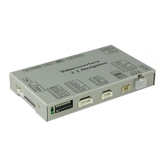
Page 5: Video-Interface
1.3.2. Video-interface The video-interface converts the connected after-market sources video signals to an LVDS signal which is the inserted into the factory monitor on certain trigger options. 1.3.2.1. Dip-switch settings Some settings must be selected by the dip-switches on the video interface. -
Page 6: Enabling The Interface's Video Inputs (Dip 1-3)
1.3.2.2. Enabling the interface’s video inputs (dip 1-3) Only the enabled video inputs can be accessed when switching through the interface’s video sources. It is recommended to enable only the required inputs for the disabled will be skipped when switching through the video interfaces inputs. 1.3.2.3. -
Page 7: Connection Schema
2.2. Connection scheme Version 07.09.2017 CI-VL2-PC-HSD / CI-NAL-PC-HSD... -
Page 8: Connecting Video-Interface And Can-Box
2.3. Connecting video-interface and CAN-box The CAN-bus box reads digital signals from the CAN-bus and converts them for the video- interface. ACC +12V max. 0.5A (red of 6pin) and reverse gear +12V max. 0.5A (green of 6pin) constant signal. Video-source switching (white of 6pin) as +12V impulse. Connect black female 10pin Micro-Fit connector of the Quadlock harness to the male 10pin Micro-Fit connector of the CAN-box. -
Page 9: Connection To The Factory Monitor
2.4. Connections to the factory monitor Remove factory monitor. Connect female 8pin Micro-Fit connector of the 4pin HSD LVDS cable to male 8pin Micro-Fit connector of the video-interface. Remove female 4pin HSD LVDS connector from the rear of the factory monitor and connect it to the male 4pin HSD LVDS connector of the 4pin HSD LVDS cable. -
Page 10: Connection To The Head-Unit
2.5. Connections to the head-unit Remove head-unit. Remove the female Quadlock connector of the vehicle harness from the rear of the navigation computer. Connect female Quadlock connector of vehicle harness to the male Quadlock connector of Quadlock harness. Connect female Quadlock connector of Quadlock harness to the male Quadlock connector of the head-unit. - Page 11 2.6.1. After-Market RGB navigation (only VL2) Connect female 8pin connector of the RGB cable to the male 8pin connector of the video-interface. The loose grey wires have no function and have to be isolated. Connect male 6pin connector of the RGB cable to the after-Market navigation. Version 07.09.2017 CI-VL2-PC-HSD / CI-NAL-PC-HSD...
-
Page 12: Video-Sources To Av1 And Av2
2.6.2. Video-sources to AV1 and AV2 Connect female 6pin connector of the audio cable to male 6pin connector of the video-interface. Connect video RCA of the AV-source 1 to the female RCA connector Video 1 of the video cable. Connect video RCA of the AV-source 2 to the female RCA connector Video 2 of the video cable. -
Page 13: Audio-Switch And Audio-Insertion
2.6.3. Audio-switch and audio insertion This interface can only insert video signals into the factory infotainment and switch audio signals. If an AV-source is connected to AV1 or AV2, audio insertion must be done by factory audio AUX input or FM-modulator to which the interface’s sound-switch output is connected. -
Page 14: After-Market Rear-View Camera
2.6.4. After-market rear-view camera Some vehicles have a different reverse gear code on the CAN-bus which the included CAN- box is not compatible with. Therefore there is two different ways of installation. If the CAN- box can detect the reverse gear in the vehicle, the green wire of the 6pin to 8pin cable should carry +12V while the reverse gear is engaged. -
Page 15: Case 2: Can-Box Does Not Detect Reverse Gear
2.6.4.2. Case 2: CAN-box does not detect reverse gear If the CAN-bus interface does not deliver +12V on the green wire of the 6pin to 8pin cable when reverse gear is engaged (not all vehicles are compatible) an external switching signal from the reverse gear light is required. -
Page 16: Video Signal Connection
2.6.4.3. Video signal connection Connect the video-RCA of the after-market rear-view camera to the female RCA port of the video-interface which is labeled as CAM. Note: Picture settings for CAM input must be done in AV2. 2.7. Connecting video-interface and keypad Connect the female 4pin connector of the keypad to the male 4pin connector of the video-interface. -
Page 17: Picture Settings And Guide Lines
2.8. Picture settings and guide lines The picture settings are adjusted by the 3 buttons on the video-interface. Press the MENU button to open the OSD settings menu or to switch to the next menu item. Press UP and DOWN change the selected value. The buttons are embedded in the housing to avoid accidental changes during or after installation. -
Page 18: Connecting Internal Navigation (Only Nal)
2.9. Connecting internal navigation (only NAL) Connect the 4pin talkover cable from Quadlock harness to the male 4pin connector of the video-interface. Connect the antenna cable of the GPS-antenna to the male GPS-antenna connector of the video-inerface. Connect red-green drilled cable of 6+2pin of 8pin cable to the male 4pin connector of the video-interface. -
Page 19: Interface Operation
Interface operation 3.1. By LIST-key The LIST-key on the steering wheel is used to switch among all the inputs. The order is: Factory video RGB-in video AV1 video AV2 factory video … Inputs which are not enabled are skipped. If the audio cable is connected, when switching from video AV1 to video AV2, also the sound will be switched. - Page 20 FAQ – Trouble shooting Interface functions For any troubles which may occur, check the following table for a solution before requesting support from your vendor. Symptom Reason Possible solution Not all connectors have been reconnected to factory head- Connect missing connectors. unit or monitor after installation.
- Page 21 Symptom Reason Possible solution Camera input picture Use relay or electronics to "clean" reverse gear lamp black. Camera power taken directly power. Alternatively, if CAN-bus box is compatible Camera input picture from reverse gear lamp. with the vehicle, camera power can be taken from green wire of 6pin to 8pin cable.
Need help?
Do you have a question about the v.LiNK CI-VL2-PC-HSD and is the answer not in the manual?
Questions and answers