Table of Contents
Advertisement
Quick Links
v.LOGiC Intelligent Solution
Compatible with E-series BMW and Mini with
navigation system or radio and 6.5" or 8.8"
monitor with 10pin BMW LVDS connector
Product features
Own on-screen display and setup
Rear-view camera input
Automatic switching to rear-view camera input on engagement of reverse gear from
all operation modes
Front camera input
Manual switching to rear-view camera (only for vehicles with PDC button)
Manual return from rear-view and front camera (cancellation of automatic switching)
2 trigger outputs (+12V max. 1A), separately adjustable switching events (CAN, ACC,
camera, reverse gear)
Picture-in-picture mode combining after-market rear-view and front camera
picture(s) with factory parking sensor graphics
Compatible with all factory video accessories (e.g. rear-view camera, Top-View,
nightvison, DVD-changer, TV-tuner)
USB update-port for software-updates by consumer
Version 05.02.2018
Interface
CI-V5-CCC-PNP
CI-V5-CCC-PNP
Advertisement
Table of Contents

Related Manuals for Car-Interface v.LOGiC CI-V5-CCC-PNP


Summary of Contents for Car-Interface v.LOGiC CI-V5-CCC-PNP
- Page 1 v.LOGiC Intelligent Solution Interface CI-V5-CCC-PNP Compatible with E-series BMW and Mini with navigation system or radio and 6.5” or 8.8” monitor with 10pin BMW LVDS connector Product features Own on-screen display and setup Rear-view camera input Automatic switching to rear-view camera input on engagement of reverse gear from all operation modes ...
-
Page 2: Table Of Contents
Contents 1. Prior to Installation 1.1. Delivery contents 1.2. Check compatibility of vehicle and accessories 1.3. Setting the dip switches of the interface-box V5C-M631 1.4. LED’s of the interface-box V5C-M631 2. Connection schema 3. Installation 3.1. Connecting interface-box and harnesses 3.2. - Page 3 Legal Information By law, watching moving pictures while driving is prohibited, the driver must not be distracted. We do not accept any liability for material damage or personal injury resulting, directly or indirectly, from installation or operation of this product. This product should only be used while standing or to display fixed menus or rear-view-camera video when the vehicle is moving, for example the MP3 menu for DVD upgrades.
-
Page 4: Prior To Installation
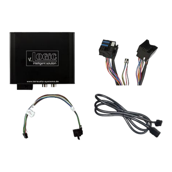
1. Prior to installation Read the manual prior to installation. Technical knowledge is necessary for installation. The place of installation must be free of moisture and away from heat sources. 1.1. Delivery contents Take down the SW-version and HW-version of the interface boxes, and store this manual for support purposes. -
Page 5: Setting The Dip Switches Of The Interface-Box V5C-M631
1.3. Setting the dip switches of the interface-box V5C-M631 Dip 1 and 2 on the back of the interface-box V5C-M631 are used to set the monitor type. The default setting is: Vehicle/ navigation Dip 1 Dip 2 Dip 3 M-ASK - version 1 M-ASK - version 2 CCC - version 1 CCC - version 2... -
Page 6: Connection Schema
2. Connection schema Version 05.02.2018 CI-V5-CCC-PNP... -
Page 7: Installation
3. Installation Switch off ignition and disconnect the vehicle’s battery! The interface needs a permanent 12V source. If according to factory rules disconnecting the battery is to be avoided, it is usually sufficient to put the vehicle is sleep-mode. In case the sleep-mode does not show success, disconnect the battery with a resistor lead. -
Page 8: Lvds Connection
Connect female 8 pin molex connector of the harness TV-BM01 to the male 8 pin molex connector of the harness TV-BM01. Connect female 12pin AMP connector of the harness TV-BM01 to the front site of the V5C-M631 interface box. 3.2. LVDS connection Interface-box V5C-M631... -
Page 9: After-Market Front Camera
3.2.1. After-market front camera 3.2.1.1. Connection to the after-market front camera Interface-Box V5C-M631 VORDERSEITE Anschlusskabel V5C-UNI01 Frontkamera +12V Kamera Power Out 1 (max. 1A) Stromversorgung Connect the video RCA of the after-market front camera to the female RCA connector “FRONT CAM” of the interface box V5C-M631. The pink wire of harness V5C-UNI01 can be used for +12V electric power supply (max. -
Page 10: Settings For Connecting An After-Market Front Camera
3.2.1.2. Settings for connecting an after-market front camera You have to configure some settings in the OSD-menus INPUTS and MISC if you want to connect an after- market front camera (Operation of the OSD: see chapter “OSD-Operation”). OSD-menu Menu item Setting Explication No front camera connected... -
Page 11: After-Market Rear-View Camera
3.2.2. After-market rear-view camera 3.2.2.1. Connection to the after-market rear-view camera Connect the video RCA of the after-market rear-view camera to the female RCA connector “REAR CAM” of the interface box V5C- M631. The green wire of harness TV-BM01 can be used for +12V electric power supply (max. -
Page 12: Settings For Connecting An After-Market Rear-View Camera
3.2.2.2. Settings for connecting an after-market rear-view camera You have to configure some settings in the OSD-menus INPUTS and MISC if you want to connect an after-market rear-view camera (Operation of the OSD: see chapter “OSD- Operation”). OSD-menu Menu item Setting Explication No rear-view camera connected... -
Page 13: Configurable Trigger Outputs
3.2.3. Configurable trigger outputs You can configure the both +12V trigger outputs separately. The pink wire is POWER OUT 1 and the green wire is POWER OUT 2. Note: You can configure the both trigger outputs in the OSD-menu MISC separately (Operation of the OSD: see chapter “OSD- Operation”). -
Page 14: Picture Settings
3.3. Picture settings You can change the picture settings in the OSD-menu IMAGE (Operation of the OSD: see chapter “OSD-Operation”). ◦ Brightness ◦ Contrast ◦ Saturation ◦ Hue ◦ Sharpness Note: The picture settings will be retained for each video source separately. Version 05.02.2018 CI-V5-CCC-PNP... -
Page 15: Operation
4. Operation 4.1. OSD – On-screen display You can change the basic configurations of the interface in the OSD (on screen display). 4.1.1. OSD – Operation You can control the OSD by iDrive. 4.1.1.1. 1- and 2-button iDrive Note: If the interface is selected as active video source then the OSD menu is activated via iDrive button "OK"... -
Page 16: 2-Button Idrive In Mini
4.1.1.2. 2-button iDrive in Mini 4.1.2. OSD – Additional setting options The following settings in the OSD-menus OSD and MISC can be configured over and above the described settings in this manual (Operation of the OSD: see chapter “OSD-Operation”): OSD-menu Menu item Setting Explication... -
Page 17: Video-In-Motion Function
4.2. Video-in-motion function It is possible to activate and deactivate the video-in-motion in the OSD menu “MISC” (Operation of the OSD: see chapter “OSD-Operation”). OSD-menu Menu item Setting Explication Video-in-motion activated MISC Video-in-motion deactivated For the V5-CIC-E-PNP the video-in-motion function is permanently active without disturbing the navigation performance. -
Page 18: Specifications
5. Specifications Operation voltage 10.5 – 14.8V DC Stand-by power drain <0,1mA Operation power drain 190mA Power consumption 2,6W Temperature range -20°C to +80°C Weight (box only) 285g Measurements (box only) B x H x T 141 x 30 x 105 mm 6.
Need help?
Do you have a question about the v.LOGiC CI-V5-CCC-PNP and is the answer not in the manual?
Questions and answers