Table of Contents
Advertisement
Quick Links
v.LiNK Video-inserter
CI-VL2-LR14-OPS
Compatible with
Land Rover vehicles
with touch-screen infotainment version 3
or
touch-screen infotainment 3.1 with 8inch 16:9 monitor
with touch-screen menu 3
Jaguar Fahrzeuge
with touch-screen infotainment version 3 and version 3.1
Video-inserter with 2 video inputs + rear-view camera input
Product features
Video-inserter for factory-infotainment systems
1 CVBS Rear-view camera video-input
2 CVBS video-inputs for after-market devices (e.g. USB-Player, DVB-T2 tuner, ...)
Built-in audio-switch (no audio-insertion)
Automatic switching to rear-view camera input on engagement of the reverse gear
Activatable parking guide lines for rear-view camera (not available for all vehicles)
Support of the factory optical park-system display (OPS)
Video-in-motion (ONLY for connected video-sources)
Video-inputs PAL and NTSC compatible
Version 17.02.2020
HW: LVDS(50)
CI-VL2-LR14-OPS
Advertisement
Table of Contents

Related Manuals for Car-Interface v.LiNK CI-VL2-LR14-OPS


Summary of Contents for Car-Interface v.LiNK CI-VL2-LR14-OPS
- Page 1 v.LiNK Video-inserter CI-VL2-LR14-OPS Compatible with Land Rover vehicles with touch-screen infotainment version 3 touch-screen infotainment 3.1 with 8inch 16:9 monitor with touch-screen menu 3 Jaguar Fahrzeuge with touch-screen infotainment version 3 and version 3.1 Video-inserter with 2 video inputs + rear-view camera input Product features ...
-
Page 2: Table Of Contents
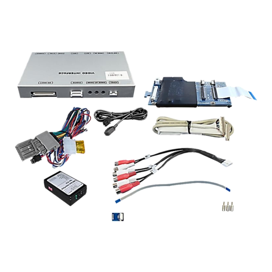
Contents 1. Prior to installation 1.1. Delivery contents 1.2. Checking the compatibility of vehicle and accessories 1.3. Boxes and connectors 1.3.1. Video-Interface 1.3.2. CAN-bus box 1.3.3. Dip-switch settings – interface (8dip – black) 1.3.3.1. Enabling the interface’s video inputs (dip 2-3) 1.3.3.2. -
Page 3: Prior To Installation
Legal Information By law, watching moving pictures while driving is prohibited, the driver must not be distracted. We do not accept any liability for material damage or personal injury resulting, directly or indirectly, from installation or operation of this product. Apart from using this product in an unmoved vehicle, it should only be used to display fixed menus or rear-view- camera video when the vehicle is moving (for example the MP3 menu for DVD upgrades). -
Page 4: Checking The Compatibility Of Vehicle And Accessories
1.2. Checking the compatibility of vehicle and accessories Requirements Brand Compatible vehicles Infotainment XF X250 model year 2012-2013 Touch-screen navi version 3 XJ X351 model year 2010-2013 (resistive touch) Jaguar F-Type model year 2013-2015 Touch-screen navi version3.1 XF X250 model year 2014-2015 (capacitive touch) XJ X351 model year 2014-2015 Range Rover Evoque L538 model year 2012-2013... -
Page 5: Boxes And Connectors
1.3. Boxes and connectors 1.3.1. Video Interface The video-interface converts the video signals of connected after-market sources in a factory monitor compatible picture signal which is inserted in the factory monitor, by using separate trigger options. 1.3.2. CAN-bus box The CAN box reads the vehicle’s digital signals out of the vehicle’s CAN-bus and converts them for the video interface. -
Page 6: Dip-Switch Settings - Interface (8Dip - Black)
1.3.3. Dip-switch settings – interface (8dip – black) Some settings have to be selected by the dip-switches on the video interface. Dip position down is ON and position up is OFF. Function ON (down) OFF (up) No function set to OFF CVBS AV1-input enabled disabled... -
Page 7: Installation
1.3.4. Dip-Schalter Einstellungen – CAN box (4dip – red) Choose the navigation, the interface shell be connected to and set dip 1 to 4 according to the below table. Fahrzeug/Infotainment Dip 1 Dip 2 Dip 3 Dip 4 All Range Rover vehicles Discovery 4 Discovery Sport Freelander 2... -
Page 8: Connection Schema
2.2. Connection schema Version 17.02.2020 HW: LVDS(50) CI-VL2-LR14-OPS... -
Page 9: Installation - Daughter Pcb
2.3. Installation – daughter PCB Turn out the 4 Torx screws at the rear side of the head unit. Turn around the head unit, carefully share the monitor part from the head unit housing, clip out and disconnect the original 50pin ribbon cable and lay the monitor part aside. Replace the mainboards original 3Torx screws against the 3 enclosed brass spacers (fix points for daughter PCB). -
Page 10: Connection - Daughter Pcb
2.4. Connection – daughter PCB To support the picture signal cable’s final out-leading, bend the left metal housing lab at 90° inwards. Connect the daughter PCB’s preassembled 50pin ribbon cable to the mainboard’s previously become free 50pin ribbon cable base and lock the connection. Connect the monitor panel’s previously become free 50pin ribbon cable to the daughter PCB’s free ribbon cable base and lock the connection. -
Page 11: Connection - Video-Interface To Power/Can
2.5. Connection - video-interface to Power / CAN Connect the 6pin to 8pin cable’s white female 6pin connector to the male 6pin connector of the video interface. Disconnect the female 16pin connector of the factory harness at the rear-side of the head unit and connect it to the 16pin Power / CAN cable’s male 16pin connector. -
Page 12: Analogue Connection - Video-Interface
2.6. Analogue connecting - video-interface If the communication between the CAN box and the vehicle’s CAN bus does not succeed (not all vehicles are compatible), an analogue connection is required by connecting the 6pin to 8pin cable without the CN box. Connect the female 6pin connector of the 6pin to 8pin cable to the 6pin connector of the video interface. -
Page 13: Connection - Picture Signal Cable
2.7. Connection - picture signal cable Connect the female 20pin connector of the picture signal cable–coming from the head unit-to the male 20pin connector of the video interface. Version 17.02.2020 HW: LVDS(50) CI-VL2-LR14-OPS... -
Page 14: Connection - Video Sources
2.8. Connection - Video-sources It is possible to connect two after-market video sources and one after-market rear-view camera to the video-interface. Before final installation of the peripheral devices, we recommend a test-run to detect a incompatibility of vehicle and interface. Due to changes in the production of the vehicle manufacturer there’s always a possibility of incompatibility. -
Page 15: Audio-Switch And Audio-Insertion
2.9. Audio-switch and audio-insertion This interface is only able to insert video signals into the factory infotainment and switch audio signals. If an AV-source is connected to AV1 or AV2, audio insertion must be done by factory audio AUX input or FM-modulator to which the interface’s sound-switch output is connected. -
Page 16: After-Market Rear-View Camera
2.10. After-market rear-view camera Some vehicles have a different reverse gear code on the CAN-bus which the included CAN- box is not compatible with. In this case there are two different ways of installation. If the CAN-box is able to detect an enabled vehicle’s reverse gear, the green wire of the 6pin to 8pin cable carries +12V while the reverse gear is engaged. -
Page 17: Case 2: Can-Box Does Not Receive The Reverse Gear Signal
2.10.2. . Case 2: CAN-box does not receive the reverse gear signal If the CAN-bus interface does not receive +12V on the green wire of the 6pin to 8pin cable when reverse gear is engaged (not all vehicles are compatible) an external switching signal from the reverse gear light is required. -
Page 18: Connection - Video Interface To External Keypad
2.11. Connection - video-interface to external keypad Connect the keypad’s female 4pin connector to the video-interface’s male 4pin connector. Note: Even if the switching through several video sources by the keypad mightn’t be required, the invisible connection and availability is strongly recommended. Version 17.02.2020 HW: LVDS(50) CI-VL2-LR14-OPS... -
Page 19: Picture Settings And Guide Lines
2.12. Picture settings and guide lines The picture settings are adjustable by the 3 push-buttons on the video-interface. Press the MENU button to open the OSD settings menu or to switch to the next menu item. Press UP and DOWN to change the selected value. The buttons are placed inside in the housing to avoid accidental changes during or after the installation. -
Page 20: Video Interface Operation
3. Video interface operation 3.1. By infotainment buttons To switch the video sources in Range Rover vehicles, the MENU button or the Navi button in Discovery 4 vehicles, the HOME button, the Menü button oder the Navi button ... -
Page 21: Specifications
4. Specifications BATT/ACC range 7V - 25V Stand-by power drain 30mA Power 180mA Video input 0.7V - 1V Video input formats NTSC/PAL RGB-video amplitude 0.7V with 75 Ohm impedance Temperature range -40°C to +85°C Dimensions video-box 157 x 21 x 100 mm (B x H x T) Dimensions CAN-box 72 x 22 x 43 mm (B x H x T) Version 17.02.2020... -
Page 22: Faq - Trouble Shooting-Interface Functions
FAQ – Trouble shooting Interface functions For any troubles which may occur, check the following table for a solution before requesting support from your vendor. Symptom Reason Possible solution Not all connectors have been reconnected to factory head- Connect missing connectors. unit or monitor after installation. - Page 23 Symptom Reason Possible solution Camera input picture Use relay or electronics to "clean" reverse gear lamp black. Camera power taken directly power. Alternatively, if CAN-bus box is compatible Camera input picture from reverse gear lamp. with the vehicle, camera power can be taken from green wire of 6pin to 8pin cable.
Need help?
Do you have a question about the v.LiNK CI-VL2-LR14-OPS and is the answer not in the manual?
Questions and answers