Chapters
Table of Contents

Related Manuals for Ametek Motec MBE5201-1


Summary of Contents for Ametek Motec MBE5201-1
- Page 1 Heavy-Duty Camera Solutions ZM-MBE5201-1 MBE5201-1 Bedienungs- und Montageanleitung Installation and operating instructions Notice de montage et d'utilisation...
-
Page 3: Table Of Contents
Umweltschutz ....................15 Allgemeine Informationen zur Bedienungsanleitung Vielen Dank für Ihr Vertrauen in AMETEK Motec Produkte. Wir entwickeln und fertigen unsere Produkte mit größter Sorgfalt. Sollten Sie Fragen zum Produkt, zur Inbetriebnahme oder Bedienung haben oder sollte das Produkt nicht Ihren Erwartungen entsprechen, sprechen Sie uns jederzeit gerne an. -
Page 4: Produktbeschreibung
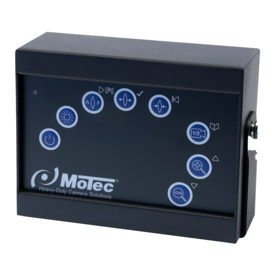
Produktbeschreibung Das Motec Krankamerasystem der Serie 5201 ermöglicht die visuelle Über- wachung verschiedener Arbeitsbereiche am Kran direkt vom Arbeitsplatz des Kranführers aus. Die Bedienung der Motorzoomkamera erfolgt über die Bedien- einheit MBE5201-1. Ein komplettes Kamerasystem besteht mindestens aus fol- genden Komponenten: TFT-Display Motorzoomkamera MC5201-1 ... -
Page 5: Konformitätserklärung
Konformitätserklärung Als Inverkehrbringer innerhalb Europas haben wir für unsere Produkte gemäß den EU-Richtlinien und gesetzlichen Vorgaben eine Konformitätsbewertung nach den Anforderungen der jeweiligen „harmonisierten Normen“ durchgeführt. Sie finden die CE-Kennzeichnung auf dem Produkt sowie auf der begleitenden Produktdokumentation. Eine EG-Konformitätserklärung stellen wir Ihnen ger- ne auf Anfrage separat zur Verfügung. -
Page 6: Abmessungen Mbe5201-1
Abmessungen MBE5201-1 Abmessungen in mm Lieferumfang Bezeichnung Matchcode Artikelnummer Bedieneinheit MBE5201-1 406 0176 009 Anschlusskabel MK59.1,5 403 0059 000 Bedienungsanleitung BA MBE5201-1 103 0000 205 Sicherheitsvorschriften Der elektrische Anschluss und die Inbetriebnahme dürfen nur von einer Fach- kraft nach den Angaben dieser Bedienungsanleitung erfolgen. Die Geräte dürfen nur in Betrieb gesetzt werden, wenn sich der Anwender über die Risiken und Gefahren, die aus der Benutzung des Gerätes resultieren, im Klaren ist. -
Page 7: Produktsicherheit
Produktsicherheit Das Produkt entspricht dem Stand der Technik und den anerkannten sicher- heitstechnischen Regeln. Das Produkt darf nur in einwandfreiem Zustand und unter Beachtung der Betriebsanleitung betrieben werden. Zusätzliche Gefahren Überprüfen Sie das Kamerasystem vor der Verwendung auf erkennbare Mängel und beobachten Sie sein Verhalten im Betrieb bzgl. -
Page 8: Elektrischer Anschluss
Die Steckverbindungen sind handfest zu verschrauben. Abgriffe von Versorgungsspannungen dürfen nur an den vom jeweiligen Her- steller dafür vorgesehenen Anschlusspunkten erfolgen. Abgriffe an Signallei- tungen führen i.d.R. zu Störungen. Elektrischer Anschluss Befestigen Sie das Bedienteil so, dass der Bediener es ohne Schwierigkeiten erreichen kann. - Page 9 Anschluss M1: Anschlussstecker Farbdisplay Pin Bezeichnung Funktion VIDSIG Video Signal VIDGND Video Schirm Versorgung Minuspol MIRH Bildspiegelung horizontal +12 V DC Versorgung Pluspol Anschluss M2: Anschlussstecker zusätzliches Anzeige- oder Videoaufzeichnungsgerät Pin Bezeichnung Funktion VIDSIG Video Signal VIDGND Video Schirm Anschluss C1: Anschlussstecker Motorzoomkamera MC5201-1 via Videoempfänger VE5201.24-1 und Videosender VS5201.24-1 Pin Bezeichnung...
-
Page 10: Vorgehensweise Für Den Elektrischen Anschluss
Anschluss C2: Anschlussstecker optionale Kompaktkamera Pin Bezeichnung Funktion Koax-Seele Video-Signal weiß Mirror schwarz Audio +12 VDC Koax-Schirm Video-GND Vorgehensweise für den elektrischen Anschluss 1) Schließen Sie das Versorgungskabel der Bedieneinheit und des Videosen- ders an die Versorgungsspannung (Dauerplus oder Zündungsplus) an. 2) Die Inbetriebnahme der Funkkomponenten wird im Kapitel 5.1 Inbetriebnah- me beschrieben. - Page 11 Konfiguration: Bedie- Funktion nungsele- Ausgabe auf Monitor NORMAL MODE Service Mode ment Ein- bzw. Ausschalten des Service Mode (schaltet sich nach ca. 20 s automatisch aus) Aus- bzw. Einschalten Auto-Focus Auto-fokus der Motorzoom- AF OFF kamera (wenn ausge- schaltet) Manuelles Fokussieren Focus der Motorzoomkamera im Zustand von „AF OFF“...
-
Page 12: Inbetriebnahme
Inbetriebnahme Es ist sinnvoll vor dem Anschluss und Montage der Systemkomponenten zu- nächst Videosender (VE5201.24-1) und Videoempfänger (VE5201.24-1) auf- einander abzustimmen. Dieser Vorgang wird im folgenden TeachIn-Prozess genannt. Der TeachIn-Prozess kann aber auch nach erfolgreichem Anschluss und Montage am Kran selber erfolgen. Durch Betätigung der Ein-/Austaste wird das System ein- bzw. -
Page 13: Einstellungen
Einstellungen Mit der Taste wird zwischen der Motorzoomkamera (C1) und einer optio- nalen Kamera (C2) (falls vorhanden) umgeschaltet. Ist keine 2. Kamera ange- schlossen, so ist der Bildschirm schwarz (kein Videosignal vorhanden). Wird die 2. Kamera (C2) z. B. als Rückfahrkamera benutzt, so kann das Bild horizontal gespiegelt werden. -
Page 14: Störungen
Funktion Beschreibung NORMAL Die Darstellung der Heavy-Duty Kamera (C2) ist normal. Die Darstellung der Heavy-Duty Kamera (C2) am Monitoranschluss MIRROR (M1) ist horizontal gespiegelt. Funktion Beschreibung Steuerleitung SEL1 = POC/Automatisches Einschalten Steuerleitung SEL2 = REAR/Umschalten auf Kamera C2 – Rück- REMOTE wärtsgang Steuerleitung SEL3 = ZOOM+/Externes Auszoomen C1... -
Page 15: Wartung/Instandhaltung
Kundeninformationen Motec GmbH Phone +49 6433 9145-9888 - Service - +49 6433 9145-9877 Oberweyerer Str. 21 motec.service@ametek.com 65589 Hadamar www.motec-cameras.com GERMANY Umweltschutz Die Verpackung besteht weitgehend aus wiederverwertbarem Material. Nutzen Sie die Möglichkeit zum umweltgerechten Recyceln der Verpackung. Altgeräte können zur umweltgerechten Entsorgung bei der nächstgelegenen Recycling-... - Page 17 Environmental protection ................29 General information about the operating instructions Thank you for your trust in AMETEK Motec products. We develop and produce our products with the greatest care. If you have questions about product, the initial set-up or the operation, or should the product not meet your expectations, please contact us and we will be happy to assist you.
-
Page 18: Product Description
Product description The Motec crane camera system series 5201 is intended for the visual monitor- ing of different work areas at the crane directly from the crane operator’s work- place. The motor zoom camera is operated via the MBE5201-1 operator control unit. -
Page 19: Declaration Of Conformity
Declaration of Conformity As European distributor, we have followed the EU Guidelines and legal rules & regulations and have implemented a conformity assessment for all our pro- ducts. The assessment is compliant with the requirements of the “Harmonised Standards”. The CE label can be found on the product as well as the applicable product documentation. -
Page 20: Dimensions Mbe5201-1
Dimensions MBE5201-1 Dimensions in mm Scope of delivery Description Match code Article number Operator control unit MBE5201-1 406 0176 008 Connection cable MK59.1,5 403 0059 000 Operating instructions BA MBE5201-1 103 0000 205 Safety instructions Only a qualified technician shall be permitted to install the electrical connection according to the information provided in the operating instructions. -
Page 21: Product Safety
Product safety The product is based on state-of-the-art technology and meets all safety regu- lations. The product must be operated only in flawless condition and compliant with the operating manual. Additional risks Prior to using the camera system, check for detectable damage and observe its operation for any malfunctions. -
Page 22: Electrical Connection
You may only tap into supply voltages at the dedicated connection points pro- vided by the corresponding manufacturer for this purpose. Tapping into signal lines usually leads to malfunction. Electrical connection Install the control unit in a location which is accessible for the operator without difficulties. - Page 23 Connection M1: Colour display connector Pin Description Function VIDSIG Video signal VIDGND Video shield Negative terminal of supply MIRH Horizontal image mirroring +12 V DC Positive terminal supply Connection M2: Connector for additional display or video recording device Pin Description Function VIDSIG Video signal...
-
Page 24: How To Proceed For Electrical Connection
Connection C2: Connector for optional compact camera Pin Description Function Coax cable core Video signal white Mirror black Audio +12 VDC Coaxial shield Video GND How to proceed for electrical connection 1) Connect the supply cable of the operator control unit and of the video trans- mitter to the supply voltage (continuous positive or ignition positive). - Page 25 Configuration: Control Function Monitor output unit NORMAL MODE Service Mode Switches the Service Mode on or off (switches off auto- matically after approx. 20 s) Switches the automatic Auto-Focus focus of the motor zoom AF OFF camera off or on (if switched off) Manual focussing of the Focus...
-
Page 26: Initial Start-Up
Initial start-up We recommend synchronising the video transmitter (VE5201.24-1) with the vi- deo receiver (VE5201.24-1) first, before connecting and installing system com- ponents. This process will be referred to as teach-in process in the following. The teach-in process can, however, also be performed after the successful connec- tion and installation at the crane. -
Page 27: Settings
Settings If you push the button, the system toggles between the motor zoom camera (C1) and an optional camera (C2) (if available). If no 2nd camera is connected, the display is black (no video signal). If the 2nd camera (C2) is used, e. g. as a rear view camera, the image can be flipped horizontally. -
Page 28: Malfunctions
Function Description OFF NORMAL The image displayed by the heavy-duty camera (C2) is normal. The image displayed by the heavy-duty camera (C2) at monitor MIRROR connection (M1) is flipped horizontally. Function Description Switch line SEL1 = POC/Automatic power-on Switch line SEL2 = REAR/Switch to camera C2 – Reverse gear OFF REMOTE Switch line SEL3 = ZOOM+/External zooming out C1 Switch line SEL4 = ZOOM-/External zooming in C1... -
Page 29: Maintenance/Repair
Phone +49 6433 9145-9888 Oberweyerer Str. 21 Fax: +49 6433 9145-9877 65589 Hadamar motec.service@ametek.com GERMANY www.motec-cameras.com Environmental protection The packaging consists mainly of recyclable material. Take advantage of the environmentally compliant recycling of the packaging. In order to comply with the environmentally correct disposal of waste electronic equipment, take the device to your nearest recycling depot or the manufacturer. - Page 31 Protection de l’environnement................ 43 Informations générales concernant la notice d’utilisation Nous vous remercions de votre confiance dans les produits AMETEK Motec. Nous concevons et fabriquons nos produits avec le plus grand soin. Si vous avez des questions sur le produit, la mise en service ou l’utilisation ou si le pro- duit ne correspond pas à...
-
Page 32: Description Du Produit
Description du produit Le système de caméra de grue Motec de la série 5201 permet la surveillance visuelle de différentes zones de travail sur la grue directement depuis le poste de travail du grutier. La manipulation de la caméra à zoom motorisé se fait par le boîtier de commande MBE5201-1. -
Page 33: Déclaration De Conformité
Déclaration de conformité En tant que distributeur au sein de l’Europe, nous avons effectué pour nos pro- duits une analyse de conformité conformément aux directives UE et aux dispo- sitions légales selon les exigences des « normes harmonisées » respectives. Vous trouverez le marquage CE sur le produit ainsi que sur la documentation produit jointe. -
Page 34: Dimensions Mbe5201-1
Dimensions MBE5201-1 Dimensions en mm Contenu de livraison Désignation Matchcode Référence Boîtier de commande MBE5201-1 406 0176 008 Câble de connexion MK59.1,5 403 0059 000 Mode d’emploi BA MBE5201-1 103 0000 205 Prescriptions de sécurité Le raccordement électrique et la mise en service doivent être effectués unique- ment par un technicien qualifié... -
Page 35: Sécurité Du Produit
Sécurité du produit Le produit correspond à l’état de la technique et aux règles de la sécurité tech- nique reconnues. Il doit être utilisé uniquement en parfait état de fonctionnement en respectant la notice technique. Dangers supplémentaires Avant utilisation, vérifiez la présence de défauts identifiables sur le système de caméras et observez le pendant qu’il fonctionne afin de détecter d’éventuels dysfonctionnements. -
Page 36: Raccordement Électrique
Des capteurs de tensions d’alimentations ne doivent être utilisés que sur les points de raccordement prévus à cet effet par le fabricant correspondant. Des capteurs sur des circuits de signalisation conduisent en général à des défauts. Raccordement électrique Fixez le dispositif de commande de manière à ce que l’opérateur puisse l’atteindre sans difficulté. - Page 37 Câble de raccordement M1 : Prise de raccordement à l’écran couleur Broche Désignation Fonction VIDSIG Signal vidéo VIDGND Blindage vidéo Alimentation pôle négatif MIRH Inversion image horizontale +12 V DC Alimentation pôle positif Câble de raccordement M2 : Prise de raccordement à l’appareil d’affichage ou d’enregistrement vidéo supplémen- taire Broche Désignation Fonction VIDSIG...
-
Page 38: Procédure Pour Le Raccordement Électrique
Câble de raccordement C2 : Prise de raccordement à la caméra compacte optionnelle Broche Désignation Fonction Âme coaxiale Signal vidéo blanc Miroir noir Audio rouge +12 VDC Blindage coaxial Vidéo GND Procédure pour le raccordement électrique 1) Branchez la câble d’alimentation du boîtier de commande et de l’émetteur vidéo sur la tension d’alimentation (plus permanent ou plus contact). - Page 39 Configuration : Élément Fonction Affichage sur le de com- moniteur MODE NORMAL Mode service mande Mise en marche et arrêt du mode service (s’éteint automatiquement après env. 20 s) Arrêt et mise en marche de Auto-Focus l’auto focus de la caméra à AF OFF zoom motorisé...
-
Page 40: Mise En Service
Mise en service Il est important de synchroniser d’abord l’émetteur vidéo (VE5201.24-1) et le ré- cepteur vidéo (VE5201.24-1) l’un avec l’autre avant le raccordement et le monta- ge des composants du système. Cette opération est mentionnée dans le proces- sus TeachIn suivant. Le processus TeachIn peut également se faire lui-même après le raccordement réussi et le montage sur la grue. -
Page 41: Réglages
coordonnés de manière à ce qu’à chaque démarrage du système, l’image vidéo apparaisse directement sur le moniteur. Réglages La touche permet la commutation entre la caméra à zoom motorisé (C1) et une caméra optionnelle (C2) (s’il y en a une). S’il n’y a pas de 2ème caméra branchée, alors l’écran est noir (il n’y a pas de signal vidéo). -
Page 42: Défauts
Fonction Description NORMAL L’affichage de la caméra Heavy Duty (C2) est normal. L’affichage de la caméra Heavy Duty (C2) sur la sortie pour moni- MIRROR teur (M1) est inversée horizontalement. Fonction Description Câble de commande SEL1 = POC/Allumage automatique Câble de commande SEL2 = REAR/Commutation sur la caméra C2 OFF REMOTE –... -
Page 43: Maintenance/Nettoyage
éventuelles demandes en garantie. Informations client Téléphone +49 6433 9145-9888 Motec GmbH +49 6433 9145-9877 - Service - motec.service@ametek.com Oberweyerer Str. 21 www.motec-cameras.com 65589 Hadamar ALLEMAGNE Protection de l’environnement L’emballage se compose en grande partie de matières recyclables. Si vous le pouvez, recyclez l’emballage dans le respect de l’environnement. - Page 44 Motec GmbH Oberweyerer Straße 21 65589 Hadamar GERMANY Phone +49 6433-9145 0 motec.info@ametek.com www.motec-cameras.com Copyright © 2018 by Motec GmbH | Art. No. 103 0000 205 BA-MBE5201-1 | 08/2018 | Subject to change without notice.
Need help?
Do you have a question about the Motec MBE5201-1 and is the answer not in the manual?
Questions and answers