Table of Contents
Advertisement
Quick Links
Advertisement
Table of Contents

Related Manuals for Supero SuperServer 6036T-3R


Summary of Contents for Supero SuperServer 6036T-3R
- Page 1 UPER ® 6036T-3R UPER ERVER USER’S MANUAL...
- Page 2 The information in this User’s Manual has been carefully reviewed and is believed to be accurate. The vendor assumes no responsibility for any inaccuracies that may be contained in this document, makes no commitment to update or to keep current the information in this manual, or to notify any person or organization of the updates.
- Page 3 About This Manual This manual is written for professional system integrators and PC technicians. It pro- vides information for the installation and use of the SuperServer 6036T-3R. Installa- tion and maintainance should be performed by experienced technicians only. The SuperServer 6036T-3R is a high-end server based on the SC835TQ-R800B 3U rackmount chassis and the X8DT3 dual processor serverboard.
- Page 4 UPER ERVER 6036T-3R User's Manual Chapter 5: Advanced Serverboard Setup Chapter 5 provides detailed information on the X8DT3 serverboard, including the locations and functions of connections, headers and jumpers. Refer to this chapter when adding or removing processors or main memory and when reconfi guring the serverboard.
- Page 5 Preface Notes...
-
Page 6: Table Of Contents
UPER ERVER 6036T-3R User's Manual Table of Contents Chapter 1 Introduction Overview ......................1-1 Serverboard Features ..................1-2 Processors ...................... 1-2 Memory ......................1-2 Onboard SAS ....................1-2 Serial ATA ....................... 1-2 PCI Expansion Slots ..................1-3 Onboard Controllers/Ports ................1-3 Graphics Controller .................. - Page 7 Table of Contents Checking the Drive Bay Setup ................ 2-9 Chapter 3 System Interface Overview ......................3-1 Control Panel Buttons ..................3-1 Reset ....................... 3-1 Power ......................3-1 Control Panel LEDs ..................3-2 Power Fail ....................... 3-2 Overheat/Fan Fail: ..................3-2 NIC1 ........................
- Page 8 Onboard Indicators ..................5-22 5-12 Floppy, SAS and SATA Ports ................ 5-23 5-13 Installing Software ..................5-25 Supero Doctor III ................... 5-26 Chapter 6 Advanced Chassis Setup Static-Sensitive Devices .................. 6-1 Precautions ..................... 6-1 Unpacking ....................... 6-1 Control Panel ....................6-2 System Fans ....................
-
Page 9: Chapter 1 Introduction
Chapter 1 Introduction Overview The SuperServer 6036T-3R is a high-end server comprised of two main subsystems: the SC835TQ-R800B 3U server chassis and the X8DT3 dual processor serverboard. Please refer to our web site for information on operating systems that have been certifi... -
Page 10: Serverboard Features
ERVER 6036T-3R User's Manual Serverboard Features At the heart of the SuperServer 6036T-3R lies the X8DT3, a dual processor serverboard based on the Intel IOH-36D + ICH10R chipset and designed to provide maximum performance. Below are the main features of the X8DT3. (See Figure 1-1 for a block diagram of the chipset). -
Page 11: Pci Expansion Slots
Chapter 1: Introduction PCI Expansion Slots The X8DT3 has three PCI Express 2.0 x8 slots, one PCI Express x4 slot and two 32-bit PCI slots. Onboard Controllers/Ports A fl oppy drive connector is included on the serverboard as well as two onboard ATA/100 connectors, which support IDE hard drives or ATAPI devices. -
Page 12: Front Control Panel
ERVER 6036T-3R User's Manual Front Control Panel The control panel on the SuperServer 6036T-3R provides you with system monitor- ing and control. LEDs indicate system power, HDD activity, network activity, system overheat and power supply failure. The main power button and a system reset button are also located here. - Page 13 Chapter 1: Introduction Figure 1-1. Intel IOH-36D/ICH10R Chipset: System Block Diagram Note: This is a general block diagram. Please see Chapter 5 for details. #1-6 #0-6 #1-5 #0-5 #1-4 #0-4 #1-3 #0-3 6 PHASE 6 PHASE #1-2 #0-2 #1-1 #0-1 CPU #2 CPU #1 (Optional)
-
Page 14: Contacting Supermicro
UPER ERVER 6036T-3R User's Manual Contacting Supermicro Headquarters Address: Super Micro Computer, Inc. 980 Rock Ave. San Jose, CA 95131 U.S.A. Tel: +1 (408) 503-8000 Fax: +1 (408) 503-8008 Email: marketing@supermicro.com (General Information) support@supermicro.com (Technical Support) Web Site: www.supermicro.com Europe Address: Super Micro Computer B.V. -
Page 15: Chapter 2 Server Installation
Precautions in the next section. Preparing for Setup The box the SuperServer 6036T-3R was shipped in should include two sets of rail assemblies, two rail mounting brackets and the mounting screws you will need to install the system into the rack. Follow the steps in the order given to complete the installation process in a minimum amount of time. -
Page 16: Rack Precautions
UPER ERVER 6036T-3R User's Manual • This product is for installation only in a Restricted Access Location (dedicated equipment rooms, service closets and the like). • This product is not suitable for use with visual display work place devices acccording to §2 of the the German Ordinance for Work with Visual Display Units. -
Page 17: Rack Mounting Considerations
Chapter 2: Server Installation Rack Mounting Considerations Ambient Operating Temperature If installed in a closed or multi-unit rack assembly, the ambient operating tempera- ture of the rack environment may be greater than the ambient temperature of the room. Therefore, consideration should be given to installing the equipment in an environment compatible with the manufacturer’s maximum rated ambient tempera- ture (Tmra). -
Page 18: Installing The System Into A Rack
UPER ERVER 6036T-3R User's Manual Installing the System into a Rack This section provides information on installing the SC835 chassis into a rack unit with the quick-release rails provided. There are a variety of rack units on the market, which may mean the assembly procedure will differ slightly. You should also refer to the installation instructions that came with the rack unit you are using. -
Page 19: Installing The Outer Rack Rails
Chapter 2: Server Installation Figure 2-2. Inner Rack Rails Installed Installing the Outer Rack Rails Outer rails attach to the server rack and hold the server in place. The outer rails for the SC835 chassis extend between 30 inches and 33 inches. Installing the Outer Rails Begin by measuring the distance from the front rail to the rear rail of the rack Attach a short bracket to the front side of the right outer rail and a long... -
Page 20: Installing The Chassis Into A Rack
UPER ERVER 6036T-3R User's Manual Figure 2-4. Installing the Chassis into the Rack Installing the Chassis into a Rack Installing into a Rack Confi rm that the inner and outer rails are installed on the rack. Line chassis rails with the front of the rack rails. Slide the chassis rails into the rack rails, keeping the pressure even on both sides (you may have to depress the locking tabs when inserting). -
Page 21: Checking The Serverboard Setup
Chapter 2: Server Installation Checking the Serverboard Setup After you install the 6036T-3R in the rack, you will need to open the unit to make sure the serverboard is properly installed and all the connections have been made. Accessing the Inside of the System (Figure 2-4) Press the release tabs to remove the cover from the locked position. - Page 22 UPER ERVER 6036T-3R User's Manual Figure 2-5. Accessing the Inside of the System Release Tab...
-
Page 23: Checking The Drive Bay Setup
Chapter 2: Server Installation Checking the Drive Bay Setup Next, you should check to make sure the peripheral drives and the SAS/SATA drives have been properly installed and all connections have been made. Checking the Drives All drives are accessable from the front of the server. For servicing the DVD- ROM and fl... - Page 24 UPER ERVER 6036T-3R User's Manual Notes 2-10...
-
Page 25: Chapter 3 System Interface
Chapter 3: System Interface Chapter 3 System Interface Overview There are several LEDs on the control panel as well as others on the drive carri- ers to keep you constantly informed of the overall status of the system as well as the activity and health of specifi... -
Page 26: Control Panel Leds
SUPERSERVER 6036T-3R User's Manual Control Panel LEDs The control panel located on the front of the chassis has several LEDs. These LEDs provide you with critical information related to different parts of the system. This section explains what each LED indicates when illuminated and any corrective action you may need to take. -
Page 27: Hdd
Chapter 3: System Interface Indicates IDE channel activity. On the SuperServer 6036T-3R, this LED indicates hard drive and/or DVD-ROM drive activity when fl ashing. Power Indicates power is being supplied to the system's power supply units. This LED should normally be illuminated when the system is operating. - Page 28 SUPERSERVER 6036T-3R User's Manual Notes...
-
Page 29: Chapter 4 System Safety
System Safety Electrical Safety Precautions Basic electrical safety precautions should be followed to protect yourself from harm and the SuperServer 6036T-3R from damage: • Be aware of the locations of the power on/off switch on the chassis as well as the room's emergency power-off switch, disconnection switch or electrical outlet. -
Page 30: General Safety Precautions
UPER ERVER 6036T-3R User's Manual • Serverboard Battery: CAUTION - There is a danger of explosion if the onboard battery is installed upside down, which will reverse its polarites (see Figure 4-1). This battery must be replaced only with the same or an equivalent type recommended by the manufacturer. -
Page 31: Esd Precautions
Chapter 4: System Safety • After accessing the inside of the system, close the system back up and secure it to the rack unit with the retention screws after ensuring that all connections have been made. ESD Precautions Electrostatic discharge (ESD) is generated by two objects with different electrical charges coming into contact with each other. -
Page 32: Operating Precautions
UPER ERVER 6036T-3R User's Manual Operating Precautions Care must be taken to assure that the chassis cover is in place when the 6036T-3R is operating to assure proper cooling. Out of warranty damage to the system can occur if this practice is not strictly followed. Figure 4-1. -
Page 33: Chapter 5 Advanced Serverboard Setup
Chapter 5: Advanced Serverboard Setup Chapter 5 Advanced Serverboard Setup This chapter covers the steps required to install the X8DT3 serverboard into the chassis, connect the data and power cables and install add-on cards. All serverboard jumpers and connections are also described. A layout and quick reference chart are included in this chapter for your reference. -
Page 34: Unpacking
UPER ERVER 6036T-3R User's Manual Unpacking The serverboard is shipped in antistatic packaging to avoid electrical static dis- charge. When unpacking the board, make sure the person handling it is static protected. Serverboard Installation This section explains the fi rst step of physically mounting the X8DT3 into the SC835TQ-R800B chassis. -
Page 35: Connecting Cables
Chapter 5: Advanced Serverboard Setup Connecting Cables Now that the serverboard is installed, the next step is to connect the cables to the board. These include the data cables for the peripherals and control panel and the power cables. Connecting Data Cables The cables used to transfer data from the peripheral devices have been carefully routed to prevent them from blocking the fl... -
Page 36: I/O Ports
UPER ERVER 6036T-3R User's Manual Figure 5-1. Control Panel Header Pins Ground x (Key) x (Key) Power On LED HDD LED NIC1 LED NIC2 LED OH/Fan Fail LED Power Fail LED Ground Reset (Button) Ground Power (Button) I/O Ports The I/O ports are color coded in conformance with the PC 99 specifi cation. See Figure 5-2 below for the colors and locations of the various I/O ports. -
Page 37: Installing The Processor And Heatsink
Chapter 5: Advanced Serverboard Setup Installing the Processor and Heatsink When handling the processor package, avoid placing direct pressure on the label area of the fan. Notes: • Always connect the power cord last and always remove it before adding, re- moving or changing any hardware components. - Page 38 UPER ERVER 6036T-3R User's Manual After removing the plastic cap, use your thumb and the index fi nger to hold the CPU at the north and south center edges. Align the CPU key (the semi-circle cutout) with the socket key (the notch below the gold color dot on the side of the socket).
-
Page 39: Installing The Heatsink
Chapter 5: Advanced Serverboard Setup Installing the Heatsink Place the heatsink on top of the CPU so that the four mounting holes are aligned with those on the retention mechanism. Screw in two diagonal screws (i.e. the #1 and the #2 screws) until just snug (do not over-tighten the screws, which may damage the CPU.) -
Page 40: Memory Support
UPER ERVER 6036T-3R User's Manual Installing Memory CAUTION! Exercise extreme care when installing or removing DIMM modules to prevent any possible damage. Memory Support The X8DT3 supports up to 96 GB of DDR3 1333/1066/800 registered ECC SDRAM. Three-way interleaved memory is supported: for optimal memory performance, install DIMMs three at a time. -
Page 41: Memory Support
Chapter 5: Advanced Serverboard Setup Memory Support The X8DT3 supports up to 96 GB of Registered ECC DDR3-1333/1066/800 MHz registered ECC SDRAM in 12 DIMM slots. DIMM sizes of 8 GB, 4 GB, 2 GB and 1 GB are supported. DIMM Module Population Confi... -
Page 42: Adding Pci Add-On Cards
UPER ERVER 6036T-3R User's Manual Possible System Memory Allocation & Availability System Device Size Physical Memory Remaining (-Available) (4 GB Total System Memory) Firmware Hub fl ash memory (System BIOS) 1 MB 3.99 GB Local APIC 4 KB 3.99 GB Area Reserved for the chipset 2 MB 3.99 GB... -
Page 43: Serverboard Details
Chapter 5: Advanced Serverboard Setup Serverboard Details Figure 5-4. X8DT3 Layout (not drawn to scale) X8DT3 COM1 LAN1 COM2 LAN2 MOUSE USB 0/1 LAN3 LAN4 Controller Controller Controller Battery Fan8/ CPU2 FAN JPW2 CPU2 BMC/VGA Controller JPG1 JBT1 JPW3 USB6/7 BIOS USB4/5 USB3... -
Page 44: X8Dt3 Quick Reference
UPER ERVER 6036T-3R User's Manual X8DT3 Quick Reference Jumper Description Default Setting JBT1 CMOS Clear See Section 5-10 C1/JI SMB to PCI Slots Pins 2-3 (Disabled) BMC Enable/Disable Pins 1-2 (Disabled) JPG1 VGA Enable/Disable Pins 1-2 (Reset) JPL1/JPL2 JLAN1/2 Enable/Disable Pins 1-2 (Enabled) JPT1 TPM Support Enable/Disable... -
Page 45: Connector Defi Nitions
Chapter 5: Advanced Serverboard Setup Connector Defi nitions ATX Power 24-pin Connector Pin Defi nitions (JPW3) Pin# Defi nition Pin # Defi nition Main ATX Power Supply +3.3V +3.3V Connector -12V +3.3V The primary power supply connec- tor (JPW3) meets the SSI EPS 12V PS_ON specifi... - Page 46 UPER ERVER 6036T-3R User's Manual Power Fail LED PWR Fail LED The Power Fail LED connection is Pin Defi nitions (JF1) located on pins 5 and 6 of JF1. Re- Pin# Defi nition fer to the table on the right for pin defi...
- Page 47 Chapter 5: Advanced Serverboard Setup Power On LED Power LED Pin Defi nitions (JF1) The Power On LED connector is lo- Pin# Defi nition cated on pins 15 and 16 of JF1 (use 5V Stby JLED for a 3-pin connector). This Control connection is used to provide LED indication of power being supplied to...
- Page 48 UPER ERVER 6036T-3R User's Manual Chassis Intrusion Chassis Intrusion Pin Defi nitions (JL1) The Chassis Intrusion header is des- Pin# Defi nition ignated JL1. Attach an appropriate Intrusion Input cable from the chassis to inform you Ground of a chassis intrusion when the chas- sis is opened Wake-On-LAN Wake-On-LAN...
- Page 49 Chapter 5: Advanced Serverboard Setup Serial Ports Serial Port Pin Defi nitions (COM1/COM2) Two serial ports are included on the Pin # Defi nition Pin # Defi nition serverboard. COM1 is a backpanel port and COM2 is a header located near the JWOL header.
- Page 50 UPER ERVER 6036T-3R User's Manual Power Supply SMBus I2C Header Power Supply SMBus I C Header Pin Defi nitions (J6) Pin# Defi nition The power System Management Bus Clock C) header is used to monitor the status of the power supply, fan and Data system temperature.
-
Page 51: 5-10 Jumper Settings
Chapter 5: Advanced Serverboard Setup 5-10 Jumper Settings Explanation of Jumpers To modify the operation of the serverboard, jumpers can be used Connector to choose between optional settings. Pins Jumpers create shorts between two pins to change the function of the con- nector. - Page 52 UPER ERVER 6036T-3R User's Manual VGA Enable/Disable VGA Enable/Disable Jumper Settings (JPG1) JPG1 allows you to enable or disable Jumper Setting Defi nition the VGA port. The default position is on Pins 1-2 Enabled pins 1 and 2 to enable VGA. See the Pins 2-3 Disabled table on the right for jumper settings.
- Page 53 Chapter 5: Advanced Serverboard Setup Watch Dog Enable/Disable Watch Dog Jumper J21 controls the Watch Dog Jumper Settings (J21) function. Watch Dog is a system moni- Jumper Setting Defi nition tor that can reboot the system when a Pins 1-2 Reset software application hangs.
-
Page 54: 5-11 Onboard Indicators
UPER ERVER 6036T-3R User's Manual 5-11 Onboard Indicators LAN LEDs The Ethernet ports (located beside the VGA port) have two LEDs. On each JLAN1/2 LED port, the yellow LED fl ashes to indi- (Connection Speed Indicator) cate activity while the other LED may LED Color Defi... -
Page 55: 5-12 Floppy, Sas And Sata Ports
Chapter 5: Advanced Serverboard Setup SAS Heartbeat/Activity LED Indicators Two SAS LEDs are located near the LSI Onboard SAS LEDs 1068E controller chip. LES1 is a SAS (LES1/LES2) Defi nition Heartbeat LED and LES2 is a SAS Ac- LES1 Blinking: SAS: Normal tivity LED. - Page 56 UPER ERVER 6036T-3R User's Manual SATA Port Pin Defi nitions (I-SATA0~I-SATA5) Pin # Defi nition SATA Ports Ground There are no jumpers to confi gure the onboard SATA ports. See the table on the right for pin defi nitions. Ground Ground Floppy Drive Connector Floppy Drive Connector...
-
Page 57: 5-13 Installing Software
Chapter 5: Advanced Serverboard Setup 5-13 Installing Software After the hardware has been installed, you should fi rst install the operating system and then the drivers. The necessary drivers are all included on the Supermicro CDs that came packaged with your motherboard. Driver/Tool Installation Display Screen Note: Click the icons showing a hand writing on paper to view the readme fi... -
Page 58: Supero Doctor Iii
ERVER 6036T-3R User's Manual Supero Doctor III The Supero Doctor III program is a Web base management tool that supports remote management capability. It includes Remote and Local Management tools. The local management is called SD III Client. The Supero Doctor III program included on the CD-ROM that came with your motherboard allows you to monitor the environment and operations of your system. - Page 59 Supero Doctor III Interface Display Screen (Remote Control) Note: SD III Software Revision 1.0 can be downloaded from our Web Site at: ftp://ftp. supermicro.com/utility/Supero_Doctor_III/. You can also download the SDIII User's Guide at: <http://www.supermicro.com/PRODUCT/Manuals/SDIII/UserGuide.pdf>. For Linux, we will recommend using Supero Doctor II. 5-27...
- Page 60 UPER ERVER 6036T-3R User's Manual Notes 5-28...
-
Page 61: Chapter 6 Advanced Chassis Setup
Chapter 6: Advanced Chassis Setup Chapter 6 Advanced Chassis Setup This chapter covers the steps required to install components and perform mainte- nance on the SC835TQ-R800B chassis. For component installation, follow the steps in the order given to eliminate the most common problems encountered. If some steps are unnecessary, skip ahead to the step that follows. -
Page 62: Control Panel
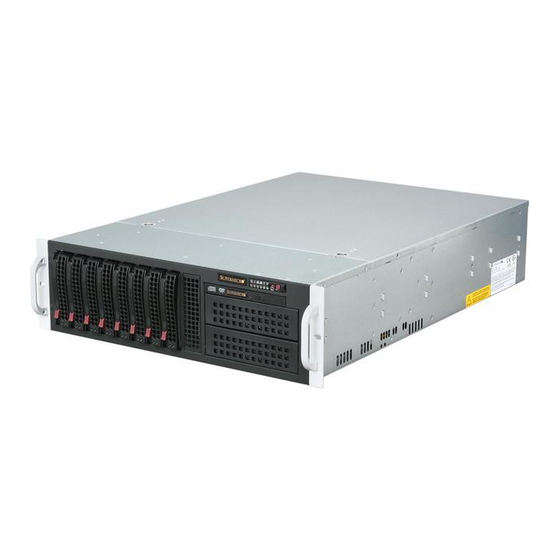
UPER ERVER 6036T-3R User's Manual Figure 6-1. Front and Rear Chassis Views Slim DVD-ROM Drive Control Panel SAS/SATA Drives (8) 3.5" Drive Bays (2) Power Supplies 7 Standard Size PCI Slots I/O Ports Control Panel The control panel (located on the front of the chassis) must be connected to the JF1 connector on the serverboard to provide you with system status indications. -
Page 63: System Fans
Chapter 6: Advanced Chassis Setup System Fans Five 8-cm hot-swap fans (two are rear exhaust fans) provide the cooling for the system. It is very important that the chassis top cover is properly installed and mak- ing a good seal in order for the cooling air to circulate properly through the chassis and cool the components. - Page 64 UPER ERVER 6036T-3R User's Manual Figure 6-2. Replacing a Rear Fan Figure 6-3. Installing the Air Shroud...
-
Page 65: Air Shroud
Chapter 6: Advanced Chassis Setup Air Shroud Air shrouds concentrate airfl ow to maximize fan effi ciency. The SC835 chassis air shroud does not require screws to set up. Installing the Air Shroud Remove the chassis cover. If necessary, remove the rear fans. Place the air shroud in the chassis (see Figure 6-3). - Page 66 UPER ERVER 6036T-3R User's Manual Installing a Hard Drive (Figures 6-4 and 6-5) Remove the two screws securing the dummy drive to the drive tray. Lift the dummy drive out of the drive tray. Place the hard drive tray on a fl at, stable surface such as a desk, table, or work bench.
- Page 67 Chapter 6: Advanced Chassis Setup Figure 6-4. Removing the Dummy Drive from the Tray Drive Tray Release Button Figure 6-5. Installing an SAS or SATA Drive to a Hard Drive Tray SAS/SATA Hard Drive Hard Drive Tray Use a hard, stable surface when installing the hard drive...
-
Page 68: Dvd-Rom Drive Installation
UPER ERVER 6036T-3R User's Manual DVD-ROM Drive Installation The SC835 chassis model supports either a slim 8x DVD-ROM, 24x CD, DVD-ROM, or an optional fl oppy disk drive. Use these instructions in this section in the event that you must replace any of these components. Installing a DVD or CD-ROM Drive (Figure 6-6) Power down and unplug the system Remove the chassis cover. -
Page 69: Power Supply
Chapter 6: Advanced Chassis Setup Power Supply The SuperServer 6036T-3R has a 800 watt redundant power supply consisting of two power modules. Each power supply module has an auto-switching capability, which enables it to automatically sense and operate at a 100V - 240V input volt- age. - Page 70 UPER ERVER 6036T-3R User's Manual Notes 6-10...
-
Page 71: Chapter 7 Bios
Chapter 7: BIOS Chapter 7 BIOS Introduction This chapter describes the AMI BIOS Setup Utility for the X8DT3. The AMI ROM BIOS is stored in a Flash EEPROM and can be easily updated. This chapter de- scribes the basic navigation of the AMI BIOS Setup Utility setup screens. Starting BIOS Setup Utility To enter the AMI BIOS Setup Utility screens, press the <Delete>... -
Page 72: Starting The Setup Utility
UPER ERVER 6036T-3R User's Manual Starting the Setup Utility Normally, the only visible Power-On Self-Test (POST) routine is the memory test. As the memory is being tested, press the <Delete> key to enter the main menu of the AMI BIOS Setup Utility. From the main menu, you can access the other setup screens. - Page 73 Chapter 7: BIOS Supermicro X8DT3 BIOS Build Version: This item displays the BIOS revision used in your system. BIOS Build Date: This item displays the date when this BIOS was completed. AMI BIOS Core Version: This item displays the revision number of the AMI BIOS Core upon which your BIOS was built.
-
Page 74: Advanced Setup Confi Gurations
UPER ERVER 6036T-3R User's Manual Advanced Setup Confi gurations Use the arrow keys to select Boot Setup and hit <Enter> to access the submenu items: BOOT Features Quick Boot If Enabled, this option will skip certain tests during POST to reduce the time needed for system boot. - Page 75 Chapter 7: BIOS Hit 'Del' Message Display This feature displays "Press DEL to run Setup" during POST. The options are Enabled and Disabled. Interrupt 19 Capture Interrupt 19 is the software interrupt that handles the boot disk function. When this item is set to Enabled, the ROM BIOS of the host adaptors will "capture"...
- Page 76 UPER ERVER 6036T-3R User's Manual Hardware Prefetcher (Available when supported by the CPU) If set to Enabled, the hardware pre fetcher will pre fetch streams of data and instruc- tions from the main memory to the L2 cache in the forward or backward manner to improve CPU performance.
- Page 77 Chapter 7: BIOS Clock Spread Spectrum Select Enable to use the feature of Clock Spectrum, which will allow the BIOS to monitor and attempt to reduce the level of Electromagnetic Interference caused by the components whenever needed. The options are Disabled and Enabled. Advanced Chipset Control The items included in the Advanced Settings submenu are listed below: CPU Bridge Confi...
- Page 78 UPER ERVER 6036T-3R User's Manual Demand Scrubbing A memory error-correction scheme where the Processor writes corrected data back into the memory block from where it was read by the Processor. The op- tions are Enabled and Disabled. Patrol Scrubbing A memory error-correction scheme that works in the background looking for and correcting resident errors.
- Page 79 Chapter 7: BIOS DIMM Pitch This is the physical space between each DIMM module. Each step is in 1/1000 of an inch. The default is [400]. Press "+" or "-" on your keyboard to change this value. North Bridge Confi guration This feature allows the user to confi...
- Page 80 UPER ERVER 6036T-3R User's Manual Legacy USB Support Select Enabled to use Legacy USB devices. If this item is set to Auto, Legacy USB support will be automatically enabled if a legacy USB device is installed on the motherboard, and vise versa. The settings are Disabled, and Enabled. USB 2.0 Controller Select Enabled to activate the onboard USB 2.0 controller.
- Page 81 Chapter 7: BIOS Host Interface. (Take caution when using this function. This feature is for ad- vanced programmers only.) The options are IDE, RAID (Intel), RAID (Adaptec) and AHCI. SATA#2 Confi guration Selecting Enhanced will set SATA#2 to native SATA mode. The options are Disabled, and Enhanced.
- Page 82 UPER ERVER 6036T-3R User's Manual Select 0 to allow the AMI BIOS to use PIO mode 0. It has a data transfer rate of 3.3 MBs. Select 1 to allow the AMI BIOS to use PIO mode 1. It has a data transfer rate of 5.2 MBs.
- Page 83 Chapter 7: BIOS Select UDMA5 to allow the BIOS to use Ultra DMA mode 5. It has a data transfer rate of 133 MBs. Select UDMA6 to allow the BIOS to use Ultra DMA mode 6. It has a data transfer rate of 133 MBs.
- Page 84 UPER ERVER 6036T-3R User's Manual PCI IDE Bus Master When enabled, the BIOS uses PCI bus mastering for reading/writing to IDE drives. The options are Disabled and Enabled. Slot 1 Option ROM~Slot 6 Option ROM Select Enabled to enable Slot 1 Option ROM~Slot 6 Option ROM, which will allow you to boot the computer from a PCI device installed on a PCI slot.
- Page 85 Chapter 7: BIOS Watch Dog Timer If enabled, the Watch Dog Timer will allow the system to reboot when it is inactive for more than 5 minutes. The options are Enabled and Disabled. Remote Access Confi guration Remote Access This allows the user to enable the Remote Access feature. The options are Dis- abled and Enabled.
- Page 86 UPER ERVER 6036T-3R User's Manual Sredir Memory Display Delay This feature defi nes the length of time in seconds to display memory information. The options are No Delay, Delay 1 Sec, Delay 2 Sec, and Delay 4 Sec. System Health Monitor This feature allows the user to monitor system health and review the status of each item as displayed.
- Page 87 Chapter 7: BIOS information that the motherboard can read. This ‘Temperature Threshold’ or ‘Tem- perature Tolerance’ has been assigned at the factory and is the baseline on which the motherboard takes action during different CPU temperature conditions (i.e., by increasing CPU Fan speed, triggering the Overheat Alarm, etc). Since CPUs can have different ‘Temperature Tolerances’, the installed CPU can now send informa- tion to the motherboard what its ‘Temperature Tolerance’...
- Page 88 UPER ERVER 6036T-3R User's Manual Voltage Monitoring CPU1 Vcore/CPU2 Vcore, CPU1 DIMM/CPU2 DIMM, 1.5V, 3.3Vcc (V), 3.3V SB (V), 12Vcc (V), 5Vin, and Battery Voltage. System Fan Monitor This feature allows the user to decide how the system controls the speeds of the onboard fans.
- Page 89 Chapter 7: BIOS pendency on other timestamp calculation devices, such as an x86 RDTSC Instruc- tion embedded in the CPU. The High Performance Event Timer is used to replace the 8254 Programmable Interval Timer. The options are Enabled and Disabled. Trusted Computing TCG/TPM (Trusted Platform Module) Support Select Yes on this item and enable the TPM jumper on the motherboard to enable...
- Page 90 UPER ERVER 6036T-3R User's Manual • Timestamp • Generator ID • Event Message Format User • Event Sensor Type • Event Sensor Number, • Event Dir Type • Event Data. Clear BMC System Event Log Clear BMC System Log Select OK and press the <Enter> key to clear the BMC system log. Select Cancel to keep the BMC System log.
- Page 91 Chapter 7: BIOS Allocation) to allow the host server to allocate an IP address based on a table containing MAC Address/IP Address pairs that are manually entered (probably by a network administrator). Only clients with a MAC address listed in the MAC/ IP Address Table will be assigned an IP address.
- Page 92 UPER ERVER 6036T-3R User's Manual Subnet Mask This item displays the current subnet mask setting for your IPMI connection. VLAN Tagging Select Enabled to enable VLAN (Virtual LAN) Tagging support which allows mul- tiple networks to transparently share the same physical network without leaking information between the bridged networks.
-
Page 93: Security Settings
Chapter 7: BIOS Event Message for PEF Action This enables of disables Event Messages for PEF action. Refer to Table 24.6 of the IPMI 1.5 Specifi cation for more information at www.intel.com. The options are Disabled and Enabled. BMC Watch Dog Timer Action Allows the BMC to reset or power down the system if the operating system hangs or crashes. -
Page 94: Boot Confi Guration
UPER ERVER 6036T-3R User's Manual Supervisor Password This item indicates if a Supervisor password has been entered for the system. "Not Installed" means a Supervisor password has not been used. User Password This item indicates if a user password has been entered for the system. "Not In- stalled"... - Page 95 Chapter 7: BIOS Boot Device Priority This feature allows the user to specify the sequence of priority for the Boot Device. The settings are 1st boot device, 2nd boot device, 3rd boot device, 4th boot device, 5th boot device and Disabled. •...
-
Page 96: Exit Options
UPER ERVER 6036T-3R User's Manual Exit Options Select the Exit tab from the AMI BIOS Setup Utility screen to enter the Exit BIOS Setup screen. Save Changes and Exit When you have completed the system confi guration changes, select this option to leave the BIOS Setup Utility and reboot the computer, so the new system con- fi... -
Page 97: Appendix A Bios Error Beep Codes
Appendix A: BIOS Error Beep Codes Appendix A BIOS Error Beep Codes During the POST (Power-On Self-Test) routines, which are performed each time the system is powered on, errors may occur. Non-fatal errors are those which, in most cases, allow the system to continue the boot-up process. - Page 98 UPER ERVER 6036T-3R User's Manual Notes...
-
Page 99: Appendix B System Specifi Cations
Appendix B: System Specifi cations Appendix B System Specifi cations Processors Single or dual Intel® Xeon 5500 Series processors in LGA1336 type sockets (both CPUs must be of the same type) Note: Please refer to our web site for a complete listing of supported processors. Chipset Intel IOH-36D/ICH10R chipset BIOS... - Page 100 UPER ERVER 6036T-3R User's Manual Serverboard X8DT3 (Extended ATX form factor) Dimensions: 12 x 13 in (305 x 330 mm) Chassis SC835TQ-R800B (3U rackmount) Dimensions: (WxHxD) 17.7 x 5.2 x 25.6 in. (450 x 132 x 650 mm) Weight Gross (Bare Bone): 75 lbs. (34 kg.) System Cooling Three 8-cm system fans and two 8-cm rear exhaust fans System Input Requirements...
- Page 101 Appendix B: System Specifi cations California Best Management Practices Regulations for Perchlorate Materials: This Perchlorate warning applies only to products containing CR (Manganese Dioxide) Lithium coin cells. “Perchlorate Material-special handling may apply. See www.dtsc.ca.gov/hazardouswaste/perchlorate”...
- Page 102 UPER ERVER 6036T-3R User's Manual (continued from front) The products sold by Supermicro are not intended for and will not be used in life support systems, medical equipment, nuclear facilities or systems, aircraft, aircraft devices, aircraft/emergency com- munication devices or other critical systems whose failure to perform be reasonably expected to result in signifi...
Need help?
Do you have a question about the SuperServer 6036T-3R and is the answer not in the manual?
Questions and answers