Table of Contents
Advertisement
Quick Links
Advertisement
Table of Contents

Related Manuals for Supero SuperServer6036T-TF


Summary of Contents for Supero SuperServer6036T-TF
- Page 1 UPER ® 6036T-TF UPER ERVER USER’S MANUAL...
- Page 2 The information in this User’s Manual has been carefully reviewed and is believed to be accurate. The vendor assumes no responsibility for any inaccuracies that may be contained in this document, makes no commitment to update or to keep current the information in this manual, or to notify any person or organization of the updates.
-
Page 3: About This Manual
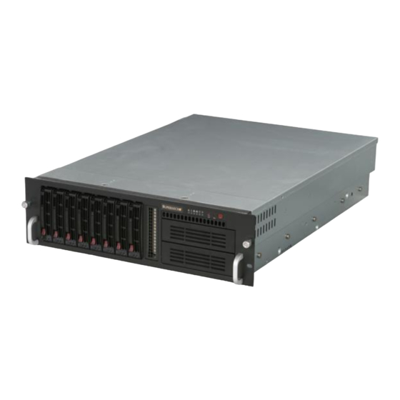
Preface Preface About This Manual This manual is written for professional system integrators and PC technicians. It provides information for the installation and use of the SuperServer 6036T-TF. Instal- lation and maintainance should be performed by experienced technicians only. The SuperServer 6036T-TF is a high-end server based on the SC833TQ-650B 3U rackmount chassis and the X8DTE-F dual processor serverboard. - Page 4 UPER ERVER 6036T-TF User's Manual Chapter 5: Advanced Serverboard Setup Chapter 5 provides detailed information on the X8DTE-F serverboard, including the locations and functions of connections, headers and jumpers. Refer to this chapter when adding or removing processors or main memory and when reconfi guring the serverboard.
- Page 5 Preface Notes...
-
Page 6: Table Of Contents
UPER ERVER 6036T-TF User's Manual Table of Contents Chapter 1 Introduction Overview ......................1-1 Serverboard Features ..................1-2 Processors ...................... 1-2 Memory ......................1-2 Serial ATA ....................... 1-2 PCI Expansion Slots ..................1-2 Onboard Controllers/Ports ................1-2 Graphics Controller ..................1-3 Other Features .................... - Page 7 Table of Contents Checking the Drive Bay Setup ..............2-10 Chapter 3 System Interface Overview ......................3-1 Control Panel Buttons ..................3-1 Mute ........................ 3-1 Reset ....................... 3-1 Power ......................3-2 Control Panel LEDs ..................3-2 Power Fail ....................... 3-2 Overheat/Fan Fail ...................
- Page 8 Onboard Indicators ..................5-22 5-12 Floppy and SATA Ports ................. 5-23 5-13 Installing Software ..................5-24 Supero Doctor III ................... 5-25 Chapter 6 Advanced Chassis Setup Static-Sensitive Devices .................. 6-1 Precautions ..................... 6-1 Control Panel ....................6-2 System Fans ....................6-3 System Fan Failure ..................
-
Page 9: Chapter 1 Introduction
Chapter 1: Introduction Chapter 1 Introduction Overview The SuperServer 6036T-TF is a high-end server comprised of two main subsys- tems: the SC833TQ-650B 3U server chassis and the X8DTE-F dual processor serverboard. Please refer to our web site for information on operating systems that have been certifi... -
Page 10: Serverboard Features
UPER ERVER 6036T-TF User's Manual Serverboard Features The SuperServer 6036T-TF is built around the X8DTE-F, a dual processor serverboard based on the Intel IOH-36D + ICH10R chipset and designed to provide maximum performance. Below are the main features of the X8DTE-F. (See Figure 1-1 for a block diagram of the chipset). -
Page 11: Graphics Controller
Chapter 1: Introduction Graphics Controller The X8DTE-F features an integrated Matrox G200eW video controller. The G200eW is a 2D/3D/video accelerator chip with a 128-bit core and 16 MB of DDR2 memory. Other Features Other onboard features that promote system health include onboard voltage moni- tors, a chassis intrusion header, auto-switching voltage regulators, chassis and CPU overheat sensors, virus protection and BIOS rescue. -
Page 12: Cooling System
UPER ERVER 6036T-TF User's Manual Cooling System The SC833TQ-650B chassis has an innovative cooling design that includes four 9-cm hot-plug system cooling fans located in the middle section of the chassis and two 8-cm hot-plug exhaust fans located at the rear of the chassis. The power sup- ply module also includes a cooling fan. -
Page 13: System Block Diagram
Chapter 1: Introduction Figure 1-1. Intel IOH-36D/ICH10R Chipset: System Block Diagram Note: This is a general block diagram. Please see Chapter 5 for details. #1-6 #0-6 #1-5 #0-5 #1-4 #0-4 #1-3 #0-3 6 PHASE 6 PHASE #1-2 #0-2 #1-1 #0-1 CPU #1 CPU #2 (Optional) -
Page 14: Contacting Supermicro
UPER ERVER 6036T-TF User's Manual Contacting Supermicro Headquarters Address: Super Micro Computer, Inc. 980 Rock Ave. San Jose, CA 95131 U.S.A. Tel: +1 (408) 503-8000 Fax: +1 (408) 503-8008 Email: marketing@supermicro.com (General Information) support@supermicro.com (Technical Support) Web Site: www.supermicro.com Europe Address: Super Micro Computer B.V. -
Page 15: Chapter 2 Server Installation
Chapter 2: Server Installation Chapter 2 Server Installation 2-1 Overview This chapter provides a quick setup checklist to get your SuperServer 6036T-TF up and running. Following these steps in the order given should enable you to have the system operational within a minimum amount of time. This quick setup assumes that your system has come to you with the processors and memory preinstalled. -
Page 16: Rack Precautions
UPER ERVER 6036T-TF User's Manual • Leave enough clearance in front of the rack to enable you to open the front door completely (~25 inches) and approximately 30 inches of clearance in the back of the rack to allow for suffi cient airfl ow and ease in servicing. •... -
Page 17: Rack Mounting Considerations
Chapter 2: Server Installation • Allow any hot plug drives and power supply modules to cool before touching them. • Always keep the rack's front door and all panels and components on the servers closed when not servicing to maintain proper cooling. Rack Mounting Considerations Ambient Operating Temperature If installed in a closed or multi-unit rack assembly, the ambient operating tempera-... -
Page 18: Installing The System Into A Rack
UPER ERVER 6036T-TF User's Manual Installing the System into a Rack This section provides information on installing the SuperServer 6036T-TF into a rack unit. If the 6036T-TF has already been mounted into a rack, you can skip ahead to Sections 2-5 and 2-6. There are a variety of rack units on the market, which may mean the assembly procedure will differ slightly. -
Page 19: Installing The Chassis Rails
Chapter 2: Server Installation Installing the Chassis Rails Position one of the fi xed chassis rail sections you just removed along the side of the 6036T-TF. Note that these two rails are left/right specifi c. Locate the fi ve rail buttons on each side of the chassis and the fi... -
Page 20: Installing The Server Into The Rack
UPER ERVER 6036T-TF User's Manual Installing the Server into the Rack Locate a pair of front (short) and rear (long) brackets that were included with your rack mounting hardware. Note that the brackets are marked with up/front arrows (front) and up/rear arrows (rear). Secure the short front bracket (A in Figure 2-3) to the outer rail with two M4 x 4 mm roundhead screws. -
Page 21: Installing The Server Into A Telco Rack
Chapter 2: Server Installation Figure 2-4. Installing the Server into a Rack Installing the Server into a Telco Rack If you are installing the SuperServer 6036T-TF into a Telco type rack, follow the directions given on the previous pages for rack installation. The only difference in the installation procedure will be the positioning of the rack brackets to the rack. -
Page 22: Checking The Serverboard Setup
UPER ERVER 6036T-TF User's Manual Checking the Serverboard Setup After you install the 6036T-TF in the rack, you will need to open the unit to make sure the serverboard is properly installed and all the connections have been made. Accessing the Inside of the System (see Figure 2-5) First, release the retention screws that secure the unit to the rack. - Page 23 Chapter 2: Server Installation Figure 2-5. Accessing the Inside of the System...
-
Page 24: Checking The Drive Bay Setup
UPER ERVER 6036T-TF User's Manual Checking the Drive Bay Setup Next, you should check to make sure the peripheral drives and the SATA drives and backplane have been properly installed and all connections have been made. Checking the Drives All drives are accessable from the front of the server. For servicing the DVD- ROM and fl... -
Page 25: Chapter 3 System Interface
Chapter 3: System Interface Chapter 3 System Interface Overview There are several LEDs on the control panel as well as others on the SATA drive carriers and the serverboard to keep you constantly informed of the overall status of the system as well as the activity and health of specifi c components. There are also three buttons on the chassis control panel. -
Page 26: Power
SUPERSERVER 6036T-TF User's Manual Power This is the main power button, which is used to apply or turn off the main system power. Turning off system power with this button removes the main power but keeps standby power supplied to the system. Control Panel LEDs The control panel located on the front of the chassis has six LEDs. -
Page 27: Nic2
Chapter 3: System Interface NIC2 Indicates network activity on LAN2 when fl ashing. NIC1 Indicates network activity on LAN1 when fl ashing. Indicates IDE channel activity. On the SuperServer 6036T-TF, this LED indicates SATA and DVD-ROM drive activity when fl ashing. Power Indicates power is being supplied to the system's power supply units. -
Page 28: Sata Drive Carrier Leds
SUPERSERVER 6036T-TF User's Manual SATA Drive Carrier LEDs Each drive carrier has two LEDs: • Green: When illuminated, the green LED on the SATA drive carrier indicates drive activity. A connection to the SATA backplane enables this LED to blink on and off when that particular drive is being accessed. -
Page 29: Chapter 4 System Safety
Chapter 4: System Safety Chapter 4 System Safety Electrical Safety Precautions Basic electrical safety precautions should be followed to protect yourself from harm and the SuperServer 6036T-TF from damage: • Be aware of the locations of the power on/off switch on the chassis as well as the room's emergency power-off switch, disconnection switch or electrical outlet. -
Page 30: General Safety Precautions
UPER ERVER 6036T-TF User's Manual • This product may be connected to an IT power system. In all cases, make sure that the unit is also reliably connected to Earth (ground). • Serverboard Battery: CAUTION - There is a danger of explosion if the onboard battery is installed upside down, which will reverse its polarites (see Figure 4-1). -
Page 31: Esd Precautions
Chapter 4: System Safety • Remove any jewelry or metal objects from your body, which are excellent metal conductors that can create short circuits and harm you if they come into contact with printed circuit boards or areas where power is present. •... -
Page 32: Operating Precautions
UPER ERVER 6036T-TF User's Manual Operating Precautions Care must be taken to assure that the chassis cover is in place when the 6036T-TF is operating to assure proper cooling. Out of warranty damage to the system can occur if this practice is not strictly followed. Figure 4-1. -
Page 33: Chapter 5 Advanced Serverboard Setup
Chapter 5: Advanced Serverboard Setup Chapter 5 Advanced Serverboard Setup This chapter covers the steps required to install the X8DTE-F serverboard into the chassis, connect the data and power cables and install add-on cards. All serverboard jumpers and connections are also described. A layout and quick reference chart are included in this chapter for your reference. -
Page 34: Unpacking
UPER ERVER 6036T-TF User's Manual Unpacking The serverboard is shipped in antistatic packaging to avoid electrical static dis- charge. When unpacking the board, make sure the person handling it is static protected. Serverboard Installation This section explains the fi rst step of physically mounting the X8DTE-F into the SC833TQ-650B chassis. -
Page 35: Connecting Cables
Chapter 5: Advanced Serverboard Setup Connecting Cables Now that the serverboard is installed, the next step is to connect the cables to the board. These include the data cables for the peripherals and control panel and the power cables. Connecting Data Cables The cables used to transfer data from the peripheral devices have been carefully routed to prevent them from blocking the fl... -
Page 36: I/O Ports
UPER ERVER 6036T-TF User's Manual Figure 5-1. Control Panel Header Pins Ground x (Key) x (Key) Power On LED HDD LED NIC1 LED NIC2 LED OH/Fan Fail LED Power Fail LED Ground Reset (Button) Ground Power (Button) I/O Ports The I/O ports are color coded in conformance with the PC 99 specifi cation. See Figure 5-2 below for the colors and locations of the various I/O ports. -
Page 37: Installing The Processor And Heatsink
Chapter 5: Advanced Serverboard Setup Installing the Processor and Heatsink When handling the processor package, avoid placing direct pressure on the label area of the fan. Notes: • Always connect the power cord last and always remove it before adding, re- moving or changing any hardware components. - Page 38 UPER ERVER 6036T-TF User's Manual After removing the plastic cap, use your thumb and the index fi nger to hold the CPU at the north and south center edges. Align the CPU key (the semi-circle cutout) with the socket key (the notch below the gold color dot on the side of the socket).
-
Page 39: Installing A Cpu Heatsink
Chapter 5: Advanced Serverboard Setup Installing a CPU Heatsink Remove power from the system and unplug the AC power cord from the power supply. Do not apply any thermal grease to the heatsink or the CPU die; the required amount has already been applied. -
Page 40: Removing The Heatsink
UPER ERVER 6036T-TF User's Manual Removing the Heatsink Warning! We do not recommend that the CPU or the heatsink be removed. However, if you do need to uninstall the heatsink, please follow the instructions below to prevent damage to the CPU or the CPU socket. -
Page 41: Installing Memory
Chapter 5: Advanced Serverboard Setup Installing Memory CAUTION! Exercise extreme care when installing or removing DIMM modules to prevent any possible damage. Memory Support The X8DTE-F supports up to 192 GB of ECC registered DDR3-1333/1066/800 or up to 48 GB of ECC unbuffered DDR3-1333/1066/800 SDRAM. Use memory modules of the same type and speed. - Page 42 UPER ERVER 6036T-TF User's Manual DIMM Module Population Confi guration Follow the table below when installing memory. Notes: Due to OS limitations, some operating systems may not show more than 4 GB of memory. Due to memory allocation to system devices, the amount of memory that remains available for operational use will be reduced when 4 GB of RAM is used.
-
Page 43: Adding Pci Add-On Cards
Chapter 5: Advanced Serverboard Setup Possible System Memory Allocation & Availability System Device Size Physical Memory Remaining (-Available) (4 GB Total System Memory) Firmware Hub fl ash memory (System BIOS) 1 MB 3.99 GB Local APIC 4 KB 3.99 GB Area Reserved for the chipset 2 MB 3.99 GB... -
Page 44: Serverboard Details
UPER ERVER 6036T-TF User's Manual Serverboard Details Figure 5-4. X8DTE-F Layout (not drawn to scale) FAN5 JPI2C1 JPW1 JPW2 JPW3 P1-DIMM3A MOUSE P1-DIMM3B FAN6 FAN1 P1-DIMM2A P1-DIMM2B P1-DIMM1A FAN7/ P1-DIMM1B CPU2 CPU1 Fan CPU1 FAN2 P2-DIMM1B LAN1 P2-DIMM1A LAN2 P2-DIMM2B JOH1 P2-DIMM2A P2-DIMM3B... -
Page 45: X8Dte-F Quick Reference
Chapter 5: Advanced Serverboard Setup X8DTE-F Quick Reference Jumper Description Default Setting JBT1 CMOS Clear (See Section 5-10) C1/JI SMB to PCI Slots Pins 2-3 (Disabled) JPG1 VGA Enable/Disable Pins 1-2 (Enabled) Watch Dog Pins 1-2 (Reset) Connector Description COM1/COM2 COM1/COM2 Serial Port/Header FAN 1-8 System/CPU Fan Headers (Fans 7~8: CPU Fans) -
Page 46: Connector Defi Nitions
UPER ERVER 6036T-TF User's Manual Connector Defi nitions ATX Power 24-pin Connector Pin Defi nitions Pin# Defi nition Pin # Defi nition Main ATX Power Supply +3.3V +3.3V Connector -12V +3.3V The primary power supply connec- tor (JPW1) meets the SSI EPS 12V PS_ON specifi... - Page 47 Chapter 5: Advanced Serverboard Setup Power Fail LED PWR Fail LED Pin Defi nitions (JF1) The Power Fail LED connection is Pin# Defi nition located on pins 5 and 6 of JF1. Re- fer to the table on the right for pin Ground defi...
- Page 48 UPER ERVER 6036T-TF User's Manual Power On LED Power LED Pin Defi nitions (JF1) The Power On LED connector is lo- Pin# Defi nition cated on pins 15 and 16 of JF1 (use 5V Stby JLED for a 3-pin connector). This Control connection is used to provide LED indication of power being supplied to...
- Page 49 Chapter 5: Advanced Serverboard Setup Chassis Intrusion Chassis Intrusion Pin Defi nitions The Chassis Intrusion header is des- Pin# Defi nition ignated JL1. Attach an appropriate Intrusion Input cable from the chassis to inform you Ground of a chassis intrusion when the chas- sis is opened Wake-On-LAN Wake-On-LAN...
- Page 50 UPER ERVER 6036T-TF User's Manual Serial Ports Serial Port Pin Defi nitions (COM1/COM2) Two serial ports are included on the Pin # Defi nition Pin # Defi nition serverboard. COM1 is a backpanel port and COM2 is a header located near the JWOL header.
- Page 51 Chapter 5: Advanced Serverboard Setup PWR SMBus Header Pin Defi nitions Power Supply SMBus I C Header Pin# Defi nition The power System Management Bus Clock header at JPI C1 is used to monitor Data the status of the power supply, fan and PWR Fail system temperature.
-
Page 52: 5-10 Jumper Settings
UPER ERVER 6036T-TF User's Manual 5-10 Jumper Settings Explanation of Jumpers To modify the operation of the serverboard, jumpers can be used Connector to choose between optional settings. Pins Jumpers create shorts between two pins to change the function of the con- nector. - Page 53 Chapter 5: Advanced Serverboard Setup VGA Enable/Disable VGA Enable/Disable Jumper Settings JPG1 allows you to enable or disable Jumper Setting Defi nition the VGA port. The default position is on Pins 1-2 Enabled pins 1 and 2 to enable VGA. See the Pins 2-3 Disabled table on the right for jumper settings.
-
Page 54: 5-11 Onboard Indicators
UPER ERVER 6036T-TF User's Manual 5-11 Onboard Indicators LAN LEDs The Ethernet ports (located beside the JLAN1/2 LED VGA port) have two LEDs. On each (Connection Speed Indicator) port, the yellow LED fl ashes to indi- LED Color Defi nition cate activity while the other LED may NC or 10 Mb/s be green, amber or off to indicate the... -
Page 55: 5-12 Floppy And Sata Ports
Chapter 5: Advanced Serverboard Setup 5-12 Floppy and SATA Ports Floppy Drive Connector Floppy Drive Connector Pin Defi nitions Pin# Defi nition Pin # Defi nition The fl oppy connector is located be- Ground FDHDIN side the IDE connector. See the table Ground Reserved below for pin defi... -
Page 56: 5-13 Installing Software
UPER ERVER 6036T-TF User's Manual 5-13 Installing Software After the hardware has been installed, you should fi rst install the operating system and then the drivers. The necessary drivers are all included on the Supermicro CDs that came packaged with your motherboard. Driver/Tool Installation Display Screen Note: Click the icons showing a hand writing on paper to view the readme fi... -
Page 57: Supero Doctor Iii
The Supero Doctor III program is a Web based management tool that supports remote management capability. It includes Remote and Local Management tools. The local management is called SD III Client. The Supero Doctor III program in- cluded on the CD-ROM that came with your motherboard allows you to monitor the environment and operations of your system. - Page 58 Supero Doctor III Interface Display Screen (Remote Control) Note: SD III Software Revision 1.0 can be downloaded from our Web Site at: ftp:// ftp.supermicro.com/utility/Supero_Doctor_III/. You can also download the SDIII User's Guide at: http://www.supermicro.com/manuals/other/SDIII_User_Guide.pdf. For Linux, we will recommend using Supero Doctor II. 5-26...
-
Page 59: Chapter 6 Advanced Chassis Setup
Chapter 6: Advanced Chassis Setup Chapter 6 Advanced Chassis Setup This chapter covers the steps required to install components and perform mainte- nance on the SC833TQ-650B. For component installation, follow the steps in the order given to eliminate the most common problems encountered. If some steps are unnecessary, skip ahead to the step that follows. -
Page 60: Control Panel
UPER ERVER 6036T-TF User's Manual Figure 6-1. Chassis: Front and Rear Views Control Panel/ Slim System LEDs DVD-ROM Drive SATA Drives (8) 5.25" Drive Bays Mute Main Power Reset Keyboard/Mouse Ports Dedicated IPMI LAN Port PCI Expansion Slots (6) Power Supply USB Ports COM1 Port VGA Port... -
Page 61: System Fans
Chapter 6: Advanced Chassis Setup System Fans Four 9-cm chassis fans, an air shroud and two 8-cm rear exhaust fans provide all the cooling needed for the 6036T-TF. It is very important that the chassis top cover is properly installed in order for the cooling air to circulate properly through the chassis and cool the components. -
Page 62: Drive Bay Installation/Removal
UPER ERVER 6036T-TF User's Manual Restore power to the system and check that the fan is working. Figure 6-2. System Cooling Fans Drive Bay Installation/Removal Accessing the Drive Bays You do not need to access the inside of the chassis to replace or swap SATA drives. Proceed to the next step for instructions. -
Page 63: Sata Drive Installation
Chapter 6: Advanced Chassis Setup SATA Drive Installation The SATA drives are mounted in drive carriers to simplify their installation and removal from the chassis. These carriers also help promote proper airfl ow for the drive bays. For this reason, even empty carriers without drives installed must remain in the chassis to cool each drive evenly. -
Page 64: Installing Components In The 5.25" Drive Bays
UPER ERVER 6036T-TF User's Manual Figure 6-4. Removing a Drive Carrier Handle Installing Components in the 5.25" Drive Bays Two 5.25" drive bays are located in the front of the chassis. Components installed to these bays are not hot-swappable, meaning system power must be turned off before installing and/or removing them. - Page 65 Chapter 6: Advanced Chassis Setup Figure 6-5. Removing a 5.25" Drive Bay DVD-ROM and Floppy Drive Installation The top cover of the chassis must be opened to gain access to the DVD-ROM and fl oppy drive bays. The 6036T-TF accomodates only slim DVD-ROM drives. Side mounting brakets are typically needed to mount a slim DVD-ROM drive in the 6036T-TF server.
- Page 66 UPER ERVER 6036T-TF User's Manual Figure 6-6. DVD-ROM Drive Installation Figure 6-7. Floppy Drive Installation...
-
Page 67: Power Supply
Chapter 6: Advanced Chassis Setup Power Supply The SuperServer 6036T-TF has a single 650 watt cold-swap power supply, which is auto-switching capable. This enables it to automatically sense and operate with a 100v - 240v input voltage. Power Supply Failure If the power supply module fails, the system will shut down and you will need to replace the module. - Page 68 UPER ERVER 6036T-TF User's Manual Notes 6-10...
-
Page 69: Chapter 7 Bios
Chapter 7: BIOS Chapter 7 BIOS Introduction This chapter describes the AMI BIOS Setup Utility for the X8DTE-F. The AMI ROM BIOS is stored in a Flash EEPROM and can be easily updated. This chapter de- scribes the basic navigation of the AMI BIOS Setup Utility setup screens. Starting BIOS Setup Utility To enter the AMI BIOS Setup Utility screens, press the <Delete>... -
Page 70: Main Setup
UPER ERVER 6036T-TF User's Manual Starting the Setup Utility Normally, the only visible Power-On Self-Test (POST) routine is the memory test. As the memory is being tested, press the <Delete> key to enter the main menu of the AMI BIOS Setup Utility. From the main menu, you can access the other setup screens. - Page 71 Chapter 7: BIOS Supermicro X8DT6/X8DTE BIOS Build Version: This item displays the BIOS revision used in your system. BIOS Build Date: This item displays the date when this BIOS was completed. AMI BIOS Core Version: This item displays the revision number of the AMI BIOS Core upon which your BIOS was built.
-
Page 72: Advanced Setup Confi Gurations
UPER ERVER 6036T-TF User's Manual Advanced Setup Confi gurations Use the arrow keys to select Boot Setup and hit <Enter> to access the submenu items: Boot Features Quick Boot If Enabled, this option will skip certain tests during POST to reduce the time needed for system boot. -
Page 73: Processor And Clock Options
Chapter 7: BIOS Hit 'Del' Message Display This feature displays "Press DEL to run Setup" during POST. The options are Enabled and Disabled. Interrupt 19 Capture Interrupt 19 is the software interrupt that handles the boot disk function. When this item is set to Enabled, the ROM BIOS of the host adaptors will "capture"... - Page 74 UPER ERVER 6036T-TF User's Manual C1E Support Select Enabled to enable Enhanced Halt State support. C1E signifi cantly reduces the CPU's power consumption by reducing the CPU's clock cycle and voltage during a "Halt State." The options are Disabled and Enabled. Hardware Prefetcher (Available when supported by the CPU) Select Enabled to enable the hardware prefetcher to prefetch streams of data and instructions from the main memory to the L2 cache in order to improve CPU per-...
-
Page 75: Advanced Chipset Control
Chapter 7: BIOS Active Processor Cores Set to Enabled to use a processor's Second Core and beyond. (Please refer to Intel's web site for more information.) The options are All, 1 and 2. Intel® Speed_Step™ Technology EIST (Enhanced Intel SpeedStep Technology) allows the system to automatically adjust processor voltage and core frequency in an effort to reduce power consump- tion and heat dissipation. - Page 76 UPER ERVER 6036T-TF User's Manual CPU Bridge Confi guration QPI (Quick_Path Interface) Links Speed This feature selects QPI's data transfer speed. The options are Slow-mode, and Full Speed. QPI Frequency This selects the desired QPI frequency. The options are Auto, 4.800 GT, 5.866GT, 6.400 GT.
- Page 77 Chapter 7: BIOS Hysteresis Temperature (Closed Loop Only) Temperature Hysteresis is the temperature lag (in degrees Celsius) after the preset DIMM temperature threshold is reached before Closed Loop Throt- tling begins. The options are Disabled, 1.5 C, 3.0 C, and 6.0 Guardband Temperature (Closed Loop Only) This is the temperature applied to the DIMM temperature threshold.
- Page 78 UPER ERVER 6036T-TF User's Manual Crystal Beach/DCA (Direct Cache Access) This feature works in conjunction with the Intel I/O AT (Acceleration Technology) to accelerate the performance of the TOE device. When this feature set to Enabled, it will enhance overall system performance by providing direct cache access for data transferring.
- Page 79 Chapter 7: BIOS Hand-Off support. When enabled, the EHCI Interface will be changed from the BIOS- controlled to the OS-controlled. The options are Disabled and Enabled. IDE/SATA Confi guration When this submenu is selected, the AMI BIOS automatically detects the presence of the IDE devices and displays the following items: SATA#1 Confi...
- Page 80 UPER ERVER 6036T-TF User's Manual Block (Multi-Sector Transfer) Block Mode boosts the IDE drive performance by increasing the amount of data transferred. Only 512 bytes of data can be transferred per interrupt if Block Mode is not used. Block Mode allows transfers of up to 64 KB per interrupt. Select Disabled to allow data to be transferred from and to the device one sector at a time.
- Page 81 Chapter 7: BIOS Select MWDMA2 to allow the BIOS to use Multi-Word DMA mode 2. It has a data transfer rate of 16.6 MBs. Select UDMA0 to allow the BIOS to use Ultra DMA mode 0. It has a data transfer rate of 16.6 MBs.
- Page 82 UPER ERVER 6036T-TF User's Manual Plug & Play OS Selecting Yes allows the OS to confi gure Plug & Play devices. (This is not required for system boot if your system has an OS that supports Plug & Play.) Select No to allow the AMI BIOS to confi...
- Page 83 Chapter 7: BIOS Port1 are Disabled, 3F8/IRQ4, 3E8/IRQ4, 2E8/IRQ3. The options for Serial Port2 are Disabled, 2F8/IRQ3, 3E8/IRQ4, and 2E8/IRQ3. Serial Port 2 Mode Use this feature to confi gure Serial Port 2 mode. The options are Normal, IrDA and ASK IR. IrDA (Infrared Data) is an industry standard for remote control de- vices.
-
Page 84: System Health Monitor
UPER ERVER 6036T-TF User's Manual Terminal Type This feature allows the user to select the target terminal type for Console Redi- rection. The options are ANSI, VT100, and VT-UTF8. VT-UTF8 Combo Key Support A terminal keyboard defi nition that provides a way to send commands from a remote console. - Page 85 Chapter 7: BIOS CPU Temperature/System Temperature This feature displays current temperature readings for the CPU and the System. The following items will be displayed for your reference only: CPU Temperature The CPU thermal technology that reports absolute temperatures (Celsius/Fahr- enheit) has been upgraded to a more advanced feature by Intel in its newer processors.
- Page 86 UPER ERVER 6036T-TF User's Manual 2. The information provided above is for your reference only. For more information on thermal management, please refer to Intel’s Web site at www.Intel.com. System Temperature: The system temperature will be displayed (in degrees in Celsius and Fahrenheit) as it is detected by the BIOS.
-
Page 87: View Bmc System Event Log
Chapter 7: BIOS Headless Mode When this feature is enabled, the system will function without a keyboard, monitor or mouse attached The options are Enabled and Disabled. High Performance Event Timer Select Enabled to activate the High Performance Event Timer (HPET) that produces periodic interrupts at a much higher frequency than a Real-time Clock (RTC) does in synchronizing multimedia streams, providing smooth playback and reducing the de- pendency on other timestamp calculation devices, such as an x86 RDTSC Instruc-... - Page 88 UPER ERVER 6036T-TF User's Manual • Event Sensor Type • Event Sensor Number, • Event Dir Type • Event Data. Clear BMC System Event Log Select OK and press the <Enter> key to clear the BMC system log. Select Cancel to keep the BMC System log.
- Page 89 Chapter 7: BIOS administrator). Only clients with an IP Address within the pre-determined range of addresses will be allowed access to the network. A static IP Address that is assigned to a device is retained until it is manually re-assigned a different address, or re-confi...
-
Page 90: Security Settings
UPER ERVER 6036T-TF User's Manual Gateway Address Confi guration This option allows to user to enter the gateway address for this machine. This should be in decimal and in dotted quad form (i.e., 192.168.10.253). The value of each three-digit number separated by dots should not exceed 255. Parameter Selector Use this feature to select the parameter of your Gateway Address settings. - Page 91 Chapter 7: BIOS Supervisor Password This item indicates if a Supervisor password has been entered for the system. "Not Installed" means a Supervisor password has not been used. User Password This item indicates if a user password has been entered for the system. "Not In- stalled"...
-
Page 92: Boot Confi Guration
UPER ERVER 6036T-TF User's Manual Password Check This item allows you to check a password after it has been entered. The options are Setup and Always. Boot Sector Virus Protection When Enabled, the AMI BIOS displays a warning when any program (or virus) is- sues a Disk Format command or attempts to write to the boot sector of the hard disk drive. - Page 93 Chapter 7: BIOS Removable Drives This feature allows the user to specify the boot sequence from available Removable Drives. The settings are 1st boot device, 2nd boot device, and Disabled. • 1st Drive - 1st Floppy Drive • 2nd Drive - [USB: XXXXXXXXX] CD/DVD Drives This feature allows the user to specify the boot sequence from available CD/DVD Drives (i.e., 1st Drive, 2nd Drive, etc).
-
Page 94: Exit Options
UPER ERVER 6036T-TF User's Manual Exit Options Select the Exit tab from the AMI BIOS Setup Utility screen to enter the Exit BIOS Setup screen. Save Changes and Exit After you have completed system confi guration changes, select this option and press <Enter>... -
Page 95: Bios Recovery
Chapter 7: BIOS BIOS Recovery Warning! Do not upgrade the BIOS unless your system has a BIOS-related issue. Flashing the wrong BIOS can cause irreparable damage to the system. In no event shall Supermicro be liable for direct, indirect, special, incidental, or consequential damages arising from a BIOS update. - Page 96 UPER ERVER 6036T-TF User's Manual Boot Sector Recovery from an IDE CD-ROM This process is almost identical to the process of Boot Sector Recovery from a USB device, except that the BIOS image fi le is loaded from a CD-ROM. Use a CD-R or CD-RW drive to burn a CD with the BIOS image fi...
- Page 97 Chapter 7: BIOS 4. Power on your system and click the <Connect> button in the Hyper Terminal. The terminal screen will display the following messages. 5. Following the instructions given on the screen to update the BIOS. These instructions are also shown below. a.
- Page 98 UPER ERVER 6036T-TF User's Manual Once the ROM fi le extraction is completed, the message: "New BIOS re- ceived OK" will display. 8. Once remote BIOS fl ash is completed, the system will reboot. Note: AMIBIOS Serial Flash will work with any terminal communications program that supports VT-100 and XModem protocols, including protocols designed for GNU/LINUX &...
-
Page 99: Appendix A Bios Error Beep Codes
Appendix A: BIOS POST Error Codes Appendix A BIOS Error Beep Codes During the POST (Power-On Self-Test) routines, which are performed each time the system is powered on, errors may occur. Non-fatal errors are those which, in most cases, allow the system to continue the boot-up process. - Page 100 UPER ERVER 6036T-TF User's Manual Notes...
-
Page 101: Appendix B Installing Windows
Appendix B: Installing the Windows OS Appendix B Installing Windows After all hardware components have been installed, you must fi rst confi gure Intel South Bridge RAID Settings before you install the Windows OS and other software drivers. To confi gure RAID settings, please refer to RAID Confi guration User Guides posted on our web site at www.supermicro.com/support/manuals. - Page 102 UPER ERVER 6036T-TF User's Manual B-2 Installing Windows for a Non-RAID System Insert Microsoft's Windows OS Setup CD in the CD drive, and the system will start booting up from CD. Continue with the OS installation. The Windows OS Setup screen will display. From the Windows OS Setup screen, press the <Enter>...
-
Page 103: Appendix C System Specifi Cations
Appendix C: System Specifi cations Appendix C System Specifi cations Processors Single or dual Intel® Xeon 5600 or 5500 Series processors in LGA1336 type sockets (both CPUs must be of the same type) Note: Please refer to our web site for a complete listing of supported processors. Chipset Intel IOH-36D/ICH10R chipset BIOS... - Page 104 UPER ERVER 6036T-TF User's Manual Chassis SC833TQ-650B (3U rackmount) Dimensions: (WxHxD) 17.1 x 5.1 x 25.5 in. (434 x 132 x 648 mm) Weight Gross (Bare Bone): 55 lbs. (25 kg.) System Cooling Four (4) 9-cm system cooling fans (hot-pluggable) Two (2) 8-cm rear exhaust fans (hot-pluggable) System Input Requirements AC Input Voltage: 100-240V AC auto-range...
- Page 105 Appendix C: System Specifi cations Notes...
- Page 106 UPER ERVER 6036T-TF User's Manual (continued from front) The products sold by Supermicro are not intended for and will not be used in life support systems, medical equipment, nuclear facilities or systems, aircraft, aircraft devices, aircraft/emergency com- munication devices or other critical systems whose failure to perform be reasonably expected to result in signifi...
Need help?
Do you have a question about the SuperServer6036T-TF and is the answer not in the manual?
Questions and answers