
Related Manuals for Supero SuperServer 6040


Summary of Contents for Supero SuperServer 6040
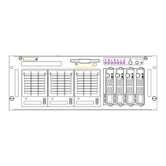
- Page 1 ® UPER 6040 UPER ERVER UPERMICR ALARM RESET SuperServer 6040 USER’S MANUAL...
- Page 2 The State of California, County of Santa Clara shall be the exclusive venue for the resolution of any such disputes. Supermicro's total liability for all claims will not exceed the price paid for the hardware product. Unless you request and receive written permission from SUPER MICRO COMPUTER, you may not copy any part of this document.
-
Page 3: Preface
Server 6040. Installation and maintainance should be performed by experi- enced technicians only. The SuperServer 6040 is a high-end dual processor 4U rackmount server based on the SC840 4U rackmount server chassis and the 370DE6, a dual processor motherboard that supports one or two 370 Pentium III FCPGA processors and 4GB registered ECC DIMM memory. - Page 4 6040 UPER ERVER Manual Chapter 5: Advanced Motherboard Setup Chapter 5 provides detailed information on the motherboard, including the locations and functions of connections, headers, jumpers and IRQs. Refer to this chapter when adding or removing processors or main memory and when reconfiguring the motherboard.
- Page 5 Chp1 Chp2 Chp3 Introduction Installation System Interface Overview Overview Overview Precautions Chassis Switches Setup Mainboard Cntrl Pnl LEDs R a c k Contact Info S C S I L E D s Installation Pwr Sply LEDs M B L E D s Manual Organization Chp4 Chp5...
-
Page 6: Table Of Contents
Choosing a Setup Location ... 2-2 Rack Precautions ... 2-2 Server Precautions ... 2-2 Installing the SuperServer 6040 into a Rack ... 2-3 Identifying the Sections of the Rack Rails ... 2-3 Installing the Chassis Rails ... 2-4 Installing the Rack Rails ... 2-4 Installing the Server into the Rack ... - Page 7 Fan Fail ... 3-3 Overheat ... 3-3 SCA Channel ... 3-3 SCSI Drive Carrier LEDs ... 3-4 Power Supply LEDs ... 3-4 Motherboard LED ... 3-4 Chapter 4: System Safety Electrical Safety Precautions ... 4-1 General Safety Precautions ... 4-2 ESD Precautions ...
- Page 8 6040 UPER ERVER Manual Fan Headers ... 5-16 Serial Ports ... 5-16 ATX PS/2 Keyboard and Mouse Ports ... 5-16 Universal Serial Bus Connector ... 5-17 Ethernet Port ... 5-17 Wake-On-LAN ... 5-17 SCSI LED ... 5-18 DIP Switch Settings ... 5-18 DIP Switch 1: Core/Bus Ratio ...
- Page 9 CD-ROM and Floppy Drive Installation ... 6-10 Power Supply Units ... 6-11 Power Supply Failure ... 6-11 Replacing Power Units ... 6-11 Chapter 7: BIOS Introduction ... 7-1 BIOS Features ... 7-2 Running Setup ... 7-2 Standard CMOS Setup ... 7-3 7-4 Advanced CMOS Setup ...
- Page 10 6040 UPER ERVER User's Manual Notes...
-
Page 11: Chapter 1: Introduction To The Superserver 6040
The Supermicro SuperServer 6040 is a high-end dual processor, 4U rackmount server that features some of the most advances technology currently available. The SuperServer 6040 is comprised of two main sub- systems: the SC840 4U rackmount chassis and the 370DE6 dual 370-pin Pentium III FCPGA processor mainboard. -
Page 12: Server Chassis Features
* Type and number depends upon the configuration ordered. Server Chassis Features The SuperServer 6040 is a high-end, scaleable 4U rackmount server plat- form designed with today's most state-of-the-art features. The following is a general outline of the main features of the SC860 chassis. -
Page 13: Cooling System
Control Panel The SuperServer 6040's detailed control panel provides comprehensive system monitoring and control. LEDs indicate network activity, power sup- ply failure, fan failure, fan status, SCSI drive activity and failure and SCA backplane overheat conditions. power button, a system reset button and an alarm reset switch. -
Page 14: Mainboard Features
UPER ERVER Manual Mainboard Features At the heart of the SuperServer 6040 lies the 370DE6, a dual processor motherboard designed to provide maximum performance in a two-way sys- tem. Below are the main features of the 370DE6. Processors The 370DE6 supports dual Pentium III FCPGA 500-1GHz MHz 100/133 MHz FSB processors. -
Page 15: Expansion Slots
Expansion Slots The 370DE6 has a total of six PCI expansion slots that consist of two 64-bit 3.3 V 66 MHz slots and four 64-bit 5V 33 MHz slots. on two separate data buses to provide a total I/O bandwidth of 792 MB/sec. In addition to the PCI slot, there is also an AGPx2 Pro slot on board. -
Page 16: Contacting Supermicro
Super Micro Computer, Inc. 2051 Junction Avenue San Jose, CA 95131 U.S.A. Tel: +1 (408) 895-2001 Fax: +1 (408) 895-2008 E-mail: marketing@supermicro.com (General Information) support@supermicro.com (Technical Support) Web site: www.supermicro.com European Office Address: Super Micro Computer B.V. Het Sterrenbeeld 28, 5215 ML,... -
Page 17: Chapter 2: Server Installation
Decide on a suitable location for the rack unit that will hold the SuperServer 6040. It should be situated in a clean, dust-free area that is well ventilated. Avoid areas where heat, electrical noise and electromagnetic fields are generated. -
Page 18: Choosing A Setup Location
6040 UPER ERVER Manual Choosing a Setup Location: - Leave enough clearance in front of the rack to enable you to open the front door completely (~25 inches). - Leave approximately 30 inches of clearance in the back of the rack to allow for sufficient airflow and ease in servicing. -
Page 19: Installing The Superserver 6040 Into A Rack
This section provides information on installing the SuperServer 6040 into a rack unit. If the 6040 has already been mounted into a rack, you can skip ahead to Sections 2-5 and 2-6. There are a variety of rack units on the market, which may mean the assembly procedure will differ slightly. -
Page 20: Installing The Chassis Rails
Installing the Chassis Rails: Position the fixed chassis rail sections you just removed along the side of the 6040 chassis making sure the five screw holes line up. Be aware that these two rails are left/right specific. Screw the rail securely to the side of the chassis (see Figure 2-2). -
Page 21: Installing The Server Into The Rack
Chapter 2: Server Installation Figure 2-3. Installing the Rack Rails Installing the Server Into the Rack: You should now have rails attached to both the chassis and the rack unit. The next step is to install the server into the chassis. Do this by lining up the rear of the chassis rails with the front of the rack rails. - Page 22 6040 UPER ERVER Manual Figure 2-4. Installing the Server Into the Rack...
-
Page 23: Checking The Motherboard Setup
Checking the Motherboard Setup After you install the 6040 in the rack, you will need to open the unit to make sure the motherboard is properly installed and all the connections have been made. 1. Accessing the inside of the 6040 (see Figure 2-5): First, release the retention screws that secure the unit to the rack. - Page 24 6040 UPER ERVER Manual Top Chassis Cover (Removed) Cover Recesses 370DE6 Exhaust Fan Motherboard Cooling Fans Processors Control Panel Figure 2-5. Accessing the Inside of the SuperServer 6040...
-
Page 25: Checking The Drive Bay Setup
Checking the Drive Bay Setup Next, you should check to make sure the peripheral drives and the SCA drives and backplane have been properly installed and all connections have been made. 1. Accessing the drive bays: All drives can be accessed from the front of the server. the CD-ROM and floppy drives, you will need to remove the top chassis cover. - Page 26 6040 UPER ERVER Manual Notes 2-10...
-
Page 27: Chapter 3: System Interface
POWER: This is the main power switch, which is used to apply or turn off the power supplied to the power supply units on the 6040. ALARM ALARM: Depressing the alarm switch will disable the audible alarm, which is generated to notify you of chassis overheating or a fan/power supply failure. -
Page 28: Control Panel Leds
NIC: Indicates network activity on the system when flashing. HDD: Indicates IDE channel activity. On the SuperServer 6040, this light indicates CD-ROM drive activity when flashing. PWR Fault: companied by an audible alarm, which you can disable with the alarm switch on the control panel. -
Page 29: Fan Fail
It is unnecessary to power down the system as these are hot-swap fans. Note: You must use the exact same brand and rating of fan for replacement. from Supermicro. Overheat: Indicates an overheat condition in the chassis. This may be caused by cables obstructing the airflow in the system, or the ambient room temperature being too warm. -
Page 30: Scsi Drive Carrier Leds
6040 UPER ERVER Manual SCSI Drive Carrier LEDs Each SCSI drive carrier has two LEDs. Green: When illuminated, the green LED on the front of the SCSI drive carrier indicates drive activity. enables this LED to blink on and off when that particular drive is being accessed. -
Page 31: Chapter 4: System Safety
Electrical Safety Precautions Basic electrical safety precautions should be followed to protect yourself from harm and the SuperServer6040 from damage: l Be aware of the locations of the power on/off switch on the chassis as well as the room's emergency power-off switch, disconnection switch or electrical outlet. -
Page 32: General Safety Precautions
General Safety Precautions Follow these rules to ensure general safety: l Keep the area around the SuperServer 6040 clean and free of clutter. l The SuperServer 6040 weighs approx. 74.8 lbs. (34 kg.) when fully loaded. When lifting the system, two people at either end should lift slowly with their feet spread out to distribute the weight. -
Page 33: Esd Precautions
Chapter 4: System Safety ESD Precautions Electrostatic discharge (ESD) is generated by two objects with different electrical charges coming into contact with each other. An electrical discharge is created to neutralize this difference, which can damage electronic components and printed circuit boards. The following measures are generally sufficient to neutralize this difference before contact is made to protect your equipment from ESD: l Use a grounded wrist strap designed to prevent static discharge. - Page 34 6040 UPER ERVER Manual Notes...
-
Page 35: Chapter 5: Advanced Motherboard Setup
Advanced Motherboard Setup This chapter covers the steps required to install the 370DE6 motherboard into the SC840 chassis, connect the data and power cables and install add- on cards. All motherboard jumpers and connections are also described. A layout and quick reference chart are on pages 5-10 and 5-11. Remember to completely close the chassis when you have finished working with the motherboard to better cool and protect the system. -
Page 36: Motherboard Installation
To remove the motherboard, follow the procedure in reverse order. Accessing the inside of the 6040 (see Figure 2-5): First, release the two retention screws that secure the unit to the rack. Grasp the two handles on either side and pull the unit straight out. - Page 37 Number of Motherboard mounting holes: 13 Figure 5-1. Mounting Holes on Motherboard (top view) respective holes in the I/O shield at the back of the chassis. Mounting the motherboard onto the motherboard tray: Carefully mount the motherboard to the motherboard tray by aligning the board holes with the metal standoffs you just installed.
-
Page 38: Connecting Cables
6040 UPER ERVER Manual Connecting Cables Now that the motherboard is installed, the next step is to connect the cables to the board. These include the data (ribbon) cables for the peripherals and front control panel, the power fail signal (PWR P) cable and the power cables. -
Page 39: Connecting The Control Panel
Connecting the Control Panel The JF1 header on the 370DE6 contains header pins for various control panel connectors. See Figure 5-2 for the locations of the speaker, overheat LED, keyboard lock, chassis intrusion, I2C, network activity LED, power fail, fan fail, 5v standby, power LED, IDE drive activity LED, power on LED, reset switch, USB0 and alarm reset headers. - Page 40 6040 UPER ERVER Manual FCPGA Processor Installation When handling the FCPGA processor package, avoid p l a c i n g direct pressure on the label area of the fan. This section covers the installation procedure for FCPGA (Flip Chip Plastic Grid Array) type processors.
-
Page 41: Removing The 370 Pentium Iii Fcpga Processors
FCPGA Socket: Empty and with Processor Installed Removing the Pentium III 370 FCPGA Processors To remove the Pentium III 370 FCPGA processors from the motherboard, follow the installation process in reverse order. When removing a Pentium III 370 FCPGA processor, avoid pressing down on the motherboard or any of its compo- n e n t s . -
Page 42: Installing Dimms
6040 UPER ERVER Manual Installing DIMMs Exercise extreme care when installing or removing DIMM modules to prevent any possible damage. Also note that the memory is interleaved to improve performance (see step 1). DIMM Installation (See Figure 5-4) 1. Insert either two or four DIMMs as required for the desired system memory. -
Page 43: Adding Pci Cards
Figure 5-5. To Remove: Use your thumbs to gently push near the edge of both ends of the module. This should release it from the slot. Adding PCI Cards 64-bit PCI slots: The 370DE6 has six 64-bit PCI slots. Two of these are 64-bit 66 MHz slots that are keyed to only accept 66 MHz, 3.3V PCI cards. - Page 44 6040 UPER ERVER Manual Figure 5-7. SUPER 370DE6 Layout PS/2 KB/ MOUSE Parallel Port COM2 3V/PCI64#2 3V/PCI64#1 JP61 5V/PCI64#4 5V/PCI64#3 JP58 (*Notes: Memory modules should be installed in pairs only.) (not drawn to scale) 13" ATX POWER #1 PWR_SEC NORTH...
- Page 45 370DE6 Quick Reference J u m p e r s Description LVD SCSI Ch A Term. LVD SCSI Ch B Term. 50pin SCSI Ch B Term JBT1 CMOS Clear FSB Speed Setting Spread Spectrum Enable JP55 3rd P/S Fail Detect Enable/Disable JP56 Speaker Enable/Disable JP57...
-
Page 46: Connector Definitions
6040 UPER ERVER Manual Connector Definitions Power Supply Connector After you have mounted the moth- erboard and added memory and PCI cards, you are ready to con- nect the cables. Attach an ATX power supply cable to ATX #1 and also to ATX#2 (for heavy load configurations. -
Page 47: Fan Fail Led
Fan Fail LED (FFL) The Fan Fail LED connection is lo- cated on pins 2 and 4 of JF1. See Table 5-4 for pin definitions and Figure 5-2 for pin locations. IDE LED The IDE Drive LED connection is located on pins 7 and 9 of JF1. This will send an indication of IDE disk activity to the front control panel. -
Page 48: Reset
6040 UPER ERVER Manual Reset The Reset connection is located on pins 15 and 17 of JF1. connector attaches to the hard- ware reset switch on the com- puter chassis. See Table 5-9 for pin definitions and Figure 5-2 for pin locations. -
Page 49: Extra Universal Serial Bus Connection
Extra Universal Serial Bus Connection (USB0) An additional connection for USB0 is included on pins 25, 27, 29, 31 and 33 of JF1 for front side USB access. You cannot have devices connected to both this and the back side connector at U25. See Table 5-12 for pin definitions and Figure 5-2 for pin locations. -
Page 50: Fan Headers
6040 UPER ERVER Manual Fan Headers* There are several fan headers on the 370DE6 to provide cooling for various components. In addition to one fan header for each proces- sor, there are one overheat and two chassis fan headers. See the motherboard layout on page 5-10 for locations. -
Page 51: Universal Serial Bus Connector
Universal Serial Bus (USB) Two Universal Serial Bus connec- tors are located beside the key- board/mouse ports. USB0 is the bottom connector and USB1 is the top connector. USB4: Extra USB Connection (J105) J105 is a five-pin headers for the USB4 port. -
Page 52: Scsi Led
6040 UPER ERVER Manual Power Supply Fail Header (For Supermciro's Triple Redundant Power Supplies only) A four-pin connector from the power supply connects to the PWR Supply Fail header (labelled JP 54) on the motherboard to no- tify you in the event of a power supply failure. -
Page 53: Jumper Settings
Core/BUS Ratio of 5.5. After determining the CPU Core/ Bus Ratio, refer to Table 5-22 for the correct settings of DIP SW 1. *Note: Most Intel Processors have a fixed Core/Bus ratio that will overwrite the setting of DIP SW1. Jumper Settings Explanation of Jumpers... -
Page 54: Scsi Enable/Disable
6040 UPER ERVER Manual Third Power Supply Failure Alarm Enable/Disable (*For Supermicro's Hot-Swap Triple Redundant Power Supplies only) The system will notify you in the event of a power supply failure. This feature assumes that three power supply units are installed in the chassis, with one acting as a backup. -
Page 55: Onboard Lan/Nic Enable/Disable
Onboard LAN/NIC Enable/Disable Use jumper JP58 to enable or dis- able the onboard LAN or NIC (Net- work Interface Card) on your motherboard. See Table 5-27 for jumper settings. LVD Channel A SCSI Termination Enable/ Disable Jumper JA2 allows you to enable or disable termination for the LVD Channel A SCSI connector. -
Page 56: 5-10 Port/Control Panel Connector Locations
6040 UPER ERVER Manual 5-10 Port/Control Panel Connector Locations The I/O ports on the 370DE6 are color coded in conformance with the PC 99 specification. These should be the last connections you make on the moth- erboard before you can apply power. See Figure 5-8 below for the colors and locations of the various I/O ports. -
Page 57: Parallel Port Connector
5-11 Parallel Port, Floppy/Hard Disk Drive and SCSI Connections Use the following information to connect the floppy and hard disk drive cables. • The floppy disk drive cable has seven twisted wires. • A red mark on a wire typically designates the location of pin 1. •... -
Page 58: Ide Connectors
6040 UPER ERVER Manual IDE Connectors There are no jumpers to config- ure the onboard IDE connectors J13 and J14. Refer to Table 5- 33 for pin definitions. 50-pin Legacy SCSI Connector Refer to Table 5-34 for pin defini- tions of the 50-pin Legacy SCSI connector located at JA5. -
Page 59: Ultra160 Scsi Connectors
Chapter 5: Advanced Motherboard Setup Ultra160 SCSI Connectors Refer to Table 5-35 for pin definitions for the Ultra160 SCSI connectors located at JA1 and JA3. Table 5-35 68-pin Ultra160 SCSI Connectors (JA1, JA3) Connector Contact N u m b e r Signal Names +DB(12) +DB(13) -
Page 60: 5-12 Irqs
6040 UPER ERVER Manual 5-12 IRQs Some PCI bus mastering devices share IRQs (Interrupt Requests) without performance penalties. See Table 5-36 for details on shared IRQs. IRQ # IRQ# 0, 1 IRQ# 2, 3 IRQ# 4, 5 IRQ# 12, 13... -
Page 61: Chapter 6: Advanced Chassis Setup
Advanced Chassis Setup This chapter covers the steps required to install components and perform maintenance on the SC840 chassis. For component installation, follow the steps in the order given to eliminate the most common problems encountered. If some steps are unnecessary, skip ahead to the step that follows. Tools Required The only tool you will need to install components and perform maintenance is a Philips screwdriver. -
Page 62: Control Panel
Figure 6-2 shows the connections, jumpers and indicators located on the control panel PCB. Details on JF1 can be found in the Chapter 5: Advanced Motherboard Installation. Control Panel System LEDs Floppy Drive SuperServer 6040 Dummy(Empty) Module (Upgradeable to a triple Redundant Power Supply) Main Power Alarm Reset... - Page 63 Power Power Override Switch Control Panel LEDs Figure 6-2. Fan Headers: (Fan designations are provided on the PCB) FAN1 cools the I/O section of the chassis FAN2 cools the AGP Pro and memory areas FAN3 directs cooling air to Processors FAN4 directs cooling air to the system and the Drive Bays FAN5 is the exhaust fan (FAN5 is on the right when viewed from the rear)
-
Page 64: System Fans
6040 UPER ERVER Manual Fan Power Override Switch: Turn this switch ON to manually supply power to the system fans. The default setting for this switch is OFF. The system cooling fans normally run at 80% of their maximum RPM to allow for this backup compensation and promote fan life. -
Page 65: Replacing System Cooling Fans
Installing a new system cooling fan: Replace the failed fan with an identical 9-cm, 12 volt fan (available from Supermicro). After the new fan has been installed, reassemble the fan housing and plug it back into its slot. You should hear it click into place when fully inserted. -
Page 66: Replacing System Exhaust Fans
6040 UPER ERVER Manual Replacing System Exhaust Fans Removing a hot-plug fan housing: With the chassis cover removed, first unplug the fan cable corresponding to the failed fan. Next, push down on the locking tabs at the top and bottom of the fan housing, which protrude through the back end of the chassis. -
Page 67: Scsi Drive Installation
SCSI Drive Installation Mounting a SCSI drive in a drive carrier: The SCSI drives are mounted in drive carriers to simplify their installation and removal from the chassis. These carriers also help promote proper airflow for the SCSI drive bays. For this reason, even empty carriers without SCSI drives installed must remain in the chassis. - Page 68 6040 UPER ERVER Manual Installing/removing hot-swap SCSI drives: Four SCSI drive bays are located in the front of the chassis, making them easily accesible to install and remove. The SCSI drives can be removed and installed without powering down the system (hot-swap).
- Page 69 SCSI Power Cables SCSI power cables should be routed in such a way that they do not block the airflow through the chassis. There is a 4-pin connector for the power cables. Connect the connector to the SCA SCSI backplane as noted in Step 3 ("Configuring the hot-plug SCSI drives").
-
Page 70: Cd-Rom And Floppy Drive Installation
6040 UPER ERVER Manual CD-ROM and Floppy Drive Installation The top cover of the chassis must be opened to gain full access to the CD- ROM and floppy drive bays. The CD-ROM drive must have a "slim" profile to fit into the 8060. -
Page 71: Power Supply Units
Power Supply Units The SC840 has a triple redundant power supply that consists of two separate 300 watt units. One unit provides a continuous 300 watts of power to the system and the second acts as a backup, which will automatically activate if one of the first unit fails. - Page 72 UPER ERVER Manual Figure 6-7. Power Supplies UPERMICR ALARM RESET SuperServer 6040 Power Supply Dummy Module Units (2) Status LED Locking Tab The power supply modules correspond with the AC power marked 1,2,3 below: Dummy module (upgradeable to a triple...
-
Page 73: Chapter 7: Bios
Introduction This chapter describes the AMIBIOS for the 370DE6 mainboard. The AMI ROM BIOS is stored in a Flash EEPROM and can be easily upgraded using a floppy disk-based program. Note: Due to periodic changes to BIOS, some settings may have been added or deleted and might not yet be recorded in this manual. -
Page 74: Bios Features
UPER ERVER 6040 Manual BIOS Features • Supports Plug and Play V1.0A and DMI 2.3 • Supports Intel PCI (Peripheral Component Interconnect) (PME) local bus specification 2.2 • Supports Advanced Power Management (APM) specification v 1.1 • Supports ACPI •... -
Page 75: The Main Bios Setup Menu
The Main BIOS Setup Menu Press the <Delete> key during the POST (Power On Self Test) to enter the Main Menu of the BIOS Setup Utility. All Main Setup options are described in this section. The Main BIOS Setup screeen is displayed below. Main Advanced Chipset PCIPnP Power Boot Security Exit AMIBIOS Version BIOS Build Date... -
Page 76: Advanced Bios Setup
UPER ERVER 6040 Manual Advanced BIOS Setup Choose Advanced BIOS Setup from the AMIBIOS Setup Utility main menu with the Left/Right arrow keys. the items in the left frame of the screen, such as SuperIO Configuration, to go to the sub screen for that item. Advanced BIOS Setup options are displayed by highlighting the option using the arrow keys. -
Page 77: Super Io Configuration
Super IO Configuration BIOS SETUP UTILITY Advanced Configure Nat317Serial Port(s)and Parallel P Serial Port1 Address Serial Port1 IRQ Serial Port2 Address Serial Port2 IRQ Parallel Port Address Parallel Port IRQ Parallel Port Mode ECP Mode DMA Channel V02.03 (C)Copyright 1985-2000, American Megatrends, Inc. The Super IO Configuration includes the following items: Serial Port 1 Address This option specifies the base I/O port address of serial port 1. -
Page 78: Ide Configuration
UPER ERVER 6040 Manual Parallel Port Address This option specifies the I/O address used by the parallel port. The settings for this item include Disabled, 378, 278 and 3BC. Select your setting and then press "Enter". Parallel Port IRQ This option allows the user to set the Parallel Port IRQ. The settings for this item include 5 and 7. - Page 79 Primary IDE Master When entering "Setup", BIOS automatically detects the presence of IDE devices. This displays the auto detection status of the IDE de vices. You can also manually configure the IDE drives by providing the following information: This option allows the user to configure the IDE devices. When the desired item is highlighted (selected), press "Enter"...
- Page 80 UPER ERVER 6040 Manual PIO Mode IDE PIO (Programmable I/O) mode programs timing cycles be tween the IDE drive and the programmable IDE controller. As the PIO mode increases, the cycle time decreases. The settings are: Auto, 0, 1, 2, 3 and 4.
- Page 81 Chapter 7: BIOS Primary IDE Slave When the system enters "Setup", BIOS automatically detects the presence of IDE devices. This option displays the auto detection status of IDE de- vices. The settings for "Primary IDE Slave" are the same as those for the "Primary IDE Master".
-
Page 82: Floppy Configuration
UPER ERVER 6040 Manual Floppy Configuration Floppy A Use this option to specify which of floppy drive you have installed in the A drive. The settings are Disabled, 360 KB 5 1/4", 1.2 MB 5 1/4", 720 KB 3 1/ 2", 1.44 MB 3 1/2"... - Page 83 Chapter 7: BIOS boot. Keep Current has the system display AMIBIOS information on bootup. BootUp Num Lock This option is used to select the status of the Number Lock function on your keyboard on bootup. The settings are On and Off. BootUp CPU Speed This option is used set the CPU speed to either High or Low.
- Page 84 UPER ERVER 6040 Manual Wait for F1 if Error This settings for this option are Enabled and Disabled. Disabled: This prevents the AMIBIOS to wait on an error for user intervention. This setting should be used if there is a known reason for a BIOS error to appear. An example would be a system administrator must remote boot the system.
-
Page 85: Event Log Configuration
Chapter 7: BIOS CPUs, write operations stored in the L1 cache aren’t copied to main memory until absolutely necessary. This is the default setting. System BIOS Cacheable This option enables you to move the system BIOS to the memory cache to improve performance. -
Page 86: Peripheral Device Configuration
UPER ERVER 6040 Manual Peripheral Device Configuration Onboard SCSI This option allows you to Enable the onboard SCSI. The settings are En- abled and Disabled. Power Lost Control This option determines how the system will respond when power is reap- plied after a power loss condition. -
Page 87: Chipset Setup
Chipset Setup Choose Chipset Setup from the AMIBIOS Setup Utility main menu. The screen is shown below. All Chipset Setup options are described following the screen. Main Advanced Chipset C000,16k Shadow C400,16k Shadow C800,16k Shadow CC00,16k Shadow D000,16k Shadow D400,16k Shadow D800,16k Shadow DC00,16k Shadow Write Combining for P6 to PCI... - Page 88 UPER ERVER 6040 Manual video ROM beginning at the above address are copied (shadowed) from ROM to RAM and can be written to or read from cache memory. settings for this option are Disabled, Enabled and Cached/WP. (The optimal settings are Cached/WP for C000 and C400 and Disabled for all the other settings.
- Page 89 Chapter 7: BIOS SDRAM Fast Timing This option defines the Fast timing settings for SDRAM . Settings include 11-1-1 and 10-1-1. MemoryWriting Posting The settings are Enabled, and Disabled. Fast ECC Enable The settings are Enabled, and Disabled. ISA IO Cycle Delay This settings for this option are Full Delay, 1.5 BCLK, 2.5 BLCK and 3.5 BLCK.
-
Page 90: Pci Pnp Setup
UPER ERVER 6040 Manual PCI PnP Setup Choose PCI/PnP Setup from the AMIBIOS Setup main menu. All PCI/PnP options are described in this section. The PCI/PnP Setup screen is shown below. Main Advanced Chipset PCIPnP Plug & Play O/S Reset Config Data... - Page 91 Chapter 7: BIOS PCI Latency Timer This option specifies the latency timing of the PCI clocks for all PCI devices. Settings include 32, 64, 96, 128, 160, 192, 224 and 248 PCI clocks. Allocate IRQ to PCI VGA This option lets you allocate an interrupt request (IRQ) to the PCI VGA adapter card (if used).
- Page 92 UPER ERVER 6040 Manual Legacy USB Support This option allows Legacy USB support. The settings are Disabled, En- abled and Auto. Disabled prevents the use of any USB device in DOS or during system boot. Enabled allows the use of USB devices during boot and while using DOS.
- Page 93 Chapter 7: BIOS Each of the above list of DMA channel setting options can be set to Avail- able and Reserved. Available means the specified DMA channel is avail- able for use by PCI/PnP devices. Reserved means the specified DMA chan- nel is reserved for use by Legacy ISA devices.
-
Page 94: Power Management
UPER ERVER 6040 Manual Power Setup Choose Power Setup from the AMIBIOS Setup main menu. All Power Setup options are described in this section. below. Main Advanced Chipset ACPI Aware O/S Power Management Power Button Mode Sleep Button Mode Green PC Monitor Power State... - Page 95 Chapter 7: BIOS Power Button Mode This option specifies how the external power button on the computer chas- sis functions. When set to On/Off, depressing the power button turns the computer on or off. When set to Suspend, depressing the power button places the computer in Suspend mode or Full On power mode.
- Page 96 UPER ERVER 6040 Manual Suspend Timeout This option specifies if BIOS is to monitor for display activity when in a power saving state. The settings include Off, 1, 2, 3, 4, 5, 6, 7, 8, 9 and 10 (minutes). IRQ1...
-
Page 97: Boot Setup
Boot Setup Choose Boot Setup from the AMIBIOS Setup main menu. options are described in this section. below. Main Advanced Chipset > Boot Device Priority > Hard Disk Drives > Removable Devices > ATAPI CDROM Drives V02.03 (C)Copyright 1985-2000, American Megatrends, Inc. Boot Device Priority 1st Boot Device This option is used to specify the order of the boot sequence that will be... -
Page 98: Hard Disk Drives
UPER ERVER 6040 Manual 3rd Boot Device The settings for the 3rd Boot Device are Removable Device, ATAPI CDROM, Hard Drive and Disabled. Hard Disk Drives Use this screen to view the boot sequence of hard drives that have been auto-detected or entered manually on your system. -
Page 99: Security Setup
Security Setup Choose Security Setup from the AMIBIOS Setup main menu. All Security Setup options are described in this section. The Security Setup screen is shown below. Main Advanced Chipset Supervisor Password User Password > Change Supervisor Password > Change User Password >... -
Page 100: Change Supervisor Password
UPER ERVER 6040 Manual Change Supervisor Password This option allows you to change a supervisor password that was entered previously. Change User Password This option allows you to change a user password that was entered previ- ously. Clear User Password Use this option to clear the user password so that it is not required to be entered when the system boots up. -
Page 101: 7-10 Exit Setup
7-10 Exit Setup Choose Exit Setup from the AMIBIOS Setup main menu. All Exit Setup op- tions are described in this section. The Exit Setup screen is shown below. Main Advanced Chipset > Exit Saving Changes > Exit Discarding Changes >... -
Page 102: Load Optimal Defaults
UPER ERVER 6040 Manual Load Optimal Defaults Highlighting this setting and then pressing <Enter> provides the optimum performance settings for all devices and system features. Load Failsafe Defaults Highlighting this setting and then pressing <Enter> provides the safest set of parameters for the system. - Page 103 Appendix A: BIOS Error Beep Codes Appendix A BIOS Error Beep Codes & Messages During the POST (Power-On Self-Test) routines, which are performed each time the system is powered on, errors may occur. Non-fatal errors are those which, in most cases, allow the system to continue the boot-up process.
- Page 104 6040 UPER ERVER Manual AMI BIOS Error Beep Codes Beep Error Message Code 1 beep Refresh 2 beeps BIOS ROM file absent 3 beeps Base 64KB memory failure 4 beeps Flash program successful 5 beeps Media read error 6 beeps...
- Page 105 Appendix B: AMIBIOS POST Diagnostic Error Messages Appendix B AMIBIOS POST Checkpoint Codes When AMIBIOS performs the Power On Self Test, it writes diagnostic codes checkpoint codes to I/O port 0080h. If the computer cannot complete the boot process, diagnostic equipment can be attached to the computer to read I/O port 0080h.
- Page 106 6040 UPER ERVER Manual B-2 Bootblock Recovery Codes The bootblock recovery checkpoint codes are listed in order of execution: Checkpoint Code Description The onboard floppy controller if available is initialized. Next, beginning the base 512 KB memory test. Initializing the interrupt vector table next.
-
Page 107: Appendix B: Amibios Post Diagnostic Error Messages
Appendix B: AMIBIOS POST Diagnostic Error Messages Initializing CMOS RAM if the Initialize CMOS RAM in every boot AMIBIOS POST option was set in AMIBCP or the <End> key was pressed. Next, disabling DMA controllers 1 and 2 and interrupt controllers 1 and 2. The video display has been disabled. - Page 108 6040 UPER ERVER Manual Checkpoint Code Description Interrupt vector initialization is done. Clearing the password if the POST DIAG switch is on. Any initialization before setting video mode will be done next. Initialization before setting the video mode is complete. Configuring the monochrome mode and color mode settings next.
- Page 109 Appendix B: AMIBIOS POST Diagnostic Error Messages Checkpoint Code Description The amount of memory above 1 MB has been found and verified. Checking for a soft reset and clearing the memory below 1 MB for the soft reset next. If this is a power on situation, going to checkpoint 4Eh next. The memory below 1 MB has been cleared via a soft reset.
- Page 110 6040 UPER ERVER Manual Checkpoint Code Description The DMA page register test passed. Performing the DMA Controller 1 base register test next. The DMA controller 1 base register test passed. Performing the DMA controller 2 base register test next. The DMA controller 2 base register test passed. Programming DMA controllers 1 and 2 next.
- Page 111 Appendix B: AMIBIOS POST Diagnostic Error Messages Checkpoint Code Description The programming after WINBIOS Setup has completed. Displaying the power on screen message next. The first screen message has been displayed. The <WAIT...> message is displayed. Performing the PS/2 mouse check and extended BIOS data area allocation check next.
- Page 112 6040 UPER ERVER Manual Checkpoint Code Description Returned after setting the RS-232 base address. Performing any required initialization before the Coprocessor test next. Required initialization before the Coprocessor test is over. Initializing the Coprocessor next. Coprocessor initialized. Performing any required initialization after the Coprocessor test next.
- Page 113 Appendix B: AMIBIOS POST Diagnostic Error Messages B-4 Bus Checkpoint Codes The system BIOS passes control to different buses at the following checkpoints: Checkpoint Code Description Initializing the different bus system, static, and output devices, if present. Initialized bus input, IPL, and general devices, if present. Displaying bus initialization error messages, if any.
- Page 114 6040 UPER ERVER Manual Notes B-10...
-
Page 115: Appendix C: List Of Figures
The following is a list of the figures in this manual and the page numbers they appear on. Figure I/O Shield Identifying the Sections of the Rack Rails Installing the Chassis Rails Installing the Rack Rails Installing the Server into the Rack Accessing the Inside of the SuperServer 8060 Mounting Holes on Motherboard Control Panel Connectors... - Page 116 6040 UPER ERVER Manual Notes...
-
Page 117: Appendix D: System Specifications
Appendix D: System Specifications Appendix D System Specifications Processors Up to two Intel 370-pin Pentium III FCPGA 600 MHz-1GHz CPUs with / 133/100 MHz FSB Memory Capacity 4 DIMM slots to support a maximum of 4 GB Registered SDRAM DIMM Sizes 128 MB / 256 MB / 512 MB / 1 GB Registered SDRAM modules supported SCSI Controller... - Page 118 6040 UPER ERVER Manual PCI Expansion Slots Two (2) 64-bit, 66 MHz PCI slots Four (4) 64/32-bit, 33 MHz PCI slots Power Supply Type: 2 x 300W redundant, hot-plug units with +3.3V, +5V, +12V, -5V and -12V main DC outputs and a 5V standby output.
Need help?
Do you have a question about the SuperServer 6040 and is the answer not in the manual?
Questions and answers