Table of Contents
Advertisement
Quick Links
Advertisement
Table of Contents

Related Manuals for Supero SuperServer 6037R-72RFT


Summary of Contents for Supero SuperServer 6037R-72RFT
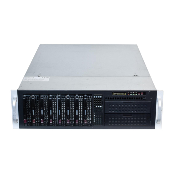
- Page 1 UPER ® UPER ERVER 6037R-72RFT USER’S MANUAL...
- Page 2 The information in this User’s Manual has been carefully reviewed and is believed to be accurate. The vendor assumes no responsibility for any inaccuracies that may be contained in this document, makes no commitment to update or to keep current the information in this manual, or to notify any person or organization of the updates.
-
Page 3: About This Manual
About This Manual This manual is written for professional system integrators and PC technicians. It provides information for the installation and use of the SuperServer 6037R-72RFT. Installation and maintainance should be performed by experienced technicians only. The SuperServer 6037R-72RFT is a high-end server based on the SC835TQ-R920B 3U rackmount chassis and the X9DRH-7TF dual processor serverboard. - Page 4 UPER ERVER 6037R-72RFT User's Manual Chapter 5: Advanced Serverboard Setup Chapter 5 provides detailed information on the X9DRH-7TF serverboard, includ- ing the locations and functions of connections, headers and jumpers. Refer to this chapter when adding or removing processors or main memory and when reconfi g- uring the serverboard.
- Page 5 Preface Notes...
-
Page 6: Table Of Contents
UPER ERVER 6037R-72RFT User's Manual Table of Contents Chapter 1 Introduction Overview ......................1-1 Serverboard Features ..................1-2 Processors ...................... 1-2 Memory ......................1-2 SAS ........................ 1-2 SATA ......................1-2 PCI Expansion Slots ..................1-2 I/O Ports ......................1-2 Graphics Controller ..................1-3 Server Chassis Features ................ - Page 7 Adding PCI Add-On Cards ................5-11 Serverboard Details ..................5-12 X9DRH-7TF Quick Reference............... 5-13 Connector Defi nitions ................... 5-15 Jumper Settings .................... 5-21 5-10 Onboard Indicators ..................5-23 5-11 SAS and SATA Ports ..................5-24 5-12 Installing Software ..................5-25 Supero Doctor III ................... 5-26...
- Page 8 UPER ERVER 6037R-72RFT User's Manual Chapter 6 Advanced Chassis Setup Static-Sensitive Devices .................. 6-1 Precautions ..................... 6-1 Unpacking ....................... 6-1 Control Panel ....................6-2 Accessing the Inside of the System..............6-3 System Fans ....................6-4 System Fan Failure ..................6-4 Replacing System Fans ..................
-
Page 9: Chapter 1 Introduction
Chapter 1 Introduction Overview The SuperServer 6037R-72RFT is a high-end server comprised of two main subsys- tems: the SC835TQ-R920B 3U server chassis and the X9DRH-7TF dual processor serverboard. Please refer to our web site for information on operating systems that have been certifi... -
Page 10: Serverboard Features
ERVER 6037R-72RFT User's Manual Serverboard Features The SuperServer 6037R-72RFT is built around the X9DRH-7TF, a dual processor serverboard based on the Intel C600 chipset and designed to provide maximum performance. Below are the main features of the X9DRH-7TF. (See Figure 1-1 for a block diagram of the chipset). -
Page 11: Graphics Controller
Front Control Panel The control panel on the SuperServer 6037R-72RFT provides you with system monitoring and control. LEDs indicate system power, HDD activity, network activity, system overheat and power supply failure. The main power button and a system reset button are also located here. - Page 12 UPER ERVER 6037R-72RFT User's Manual Figure 1-1. Chipset Block Diagram Note: This is a general block diagram. Please see Chapter 5 for details. #H-2 #H-1 #D-2 #G-2 #G-1 #C-2 #C-1 #F-2 #F-1 #B-2 #B-1 #E-2 #A-2 #E-1 E5-2600 E5-2600 #A-1 8 SNB CORE 8 SNB CORE DDR-III...
-
Page 13: Contacting Supermicro
Chapter 1: Introduction Contacting Supermicro Headquarters Address: Super Micro Computer, Inc. 980 Rock Ave. San Jose, CA 95131 U.S.A. Tel: +1 (408) 503-8000 Fax: +1 (408) 503-8008 Email: marketing@supermicro.com (General Information) support@supermicro.com (Technical Support) Web Site: www.supermicro.com Europe Address: Super Micro Computer B.V. Het Sterrenbeeld 28, 5215 ML 's-Hertogenbosch, The Netherlands Tel:... - Page 14 UPER ERVER 6037R-72RFT User's Manual Notes...
-
Page 15: Chapter 2 Server Installation
Unpacking the System You should inspect the box the SuperServer 6037R-72RFT was shipped in and note if it was damaged in any way. If the server itself shows damage you should fi le a damage claim with the carrier who delivered it. -
Page 16: Rack Precautions
UPER ERVER 6037R-72RFT User's Manual • This product is for installation only in a Restricted Access Location (dedicated equipment rooms, service closets and the like). • This product is not suitable for use with visual display work place devices acccording to §2 of the the German Ordinance for Work with Visual Display Units. -
Page 17: Rack Mounting Considerations
Chapter 2: Server Installation Rack Mounting Considerations Ambient Operating Temperature If installed in a closed or multi-unit rack assembly, the ambient operating tempera- ture of the rack environment may be greater than the ambient temperature of the room. Therefore, consideration should be given to installing the equipment in an environment compatible with the manufacturer’s maximum rated ambient tempera- ture (Tmra). -
Page 18: Installing The System Into A Rack
UPER ERVER 6037R-72RFT User's Manual Installing the System into a Rack This section provides information on installing the SC835 chassis into a rack unit with the quick-release rails provided. There are a variety of rack units on the market, which may mean the assembly procedure will differ slightly. You should also refer to the installation instructions that came with the rack unit you are using. -
Page 19: Installing The Outer Rack Rails
Chapter 2: Server Installation Figure 2-2. Inner Rack Rails Installed Installing the Outer Rack Rails Outer rails attach to the server rack and hold the server in place. The outer rails for the SC835 chassis extend between 30 inches and 33 inches. Installing the Outer Rails 1. -
Page 20: Installing The Chassis Into A Rack
UPER ERVER 6037R-72RFT User's Manual Figure 2-4. Installing the Chassis into the Rack Installing the Chassis into a Rack Installing into a Rack 1. Confi rm that the inner and outer rails are installed on the rack. 2. Line chassis rails with the front of the rack rails. 3. -
Page 21: Chapter 3 System Interface
Chapter 3: System Interface Chapter 3 System Interface Overview There are several LEDs on the control panel as well as others on the drive carri- ers to keep you constantly informed of the overall status of the system as well as the activity and health of specifi... -
Page 22: Control Panel Leds
SUPERSERVER 6037R-72RFT User's Manual Control Panel LEDs The control panel located on the front of the chassis has several LEDs. These LEDs provide you with critical information related to different parts of the system. This section explains what each LED indicates when illuminated and any corrective action you may need to take. -
Page 23: Hdd
Chapter 3: System Interface On the SuperServer 6037R-72RFT, this LED indicates SATA hard drive and/or DVD-ROM drive activity when fl ashing. Power Indicates power is being supplied to the system's power supply units. This LED should normally be illuminated when the system is operating. - Page 24 SUPERSERVER 6037R-72RFT User's Manual Notes...
-
Page 25: Chapter 4 System Safety
System Safety Electrical Safety Precautions Basic electrical safety precautions should be followed to protect yourself from harm and the SuperServer 6037R-72RFT from damage: • Be aware of the locations of the power on/off switch on the chassis as well as the room's emergency power-off switch, disconnection switch or electrical outlet. -
Page 26: General Safety Precautions
UPER ERVER 6037R-72RFT User's Manual • This product may be connected to an IT power system. In all cases, make sure that the unit is also reliably connected to Earth (ground). • Serverboard Battery: CAUTION - There is a danger of explosion if the onboard battery is installed upside down, which will reverse its polarites (see Figure 4-1). -
Page 27: Esd Precautions
Chapter 4: System Safety • Remove any jewelry or metal objects from your body, which are excellent metal conductors that can create short circuits and harm you if they come into contact with printed circuit boards or areas where power is present. •... -
Page 28: Operating Precautions
UPER ERVER 6037R-72RFT User's Manual Operating Precautions Care must be taken to assure that the chassis cover is in place when the 6037R- 72RFT is operating to assure proper cooling. Out of warranty damage to the system can occur if this practice is not strictly followed. Figure 4-1. -
Page 29: Chapter 5 Advanced Serverboard Setup
Chapter 5: Advanced Serverboard Setup Chapter 5 Advanced Serverboard Setup This chapter covers the steps required to install the X9DRH-7TF serverboard into the chassis, connect the data and power cables and install add-on cards. All serverboard jumpers and connections are also described. A layout and quick reference chart are included in this chapter for your reference. -
Page 30: Unpacking
UPER ERVER 6037R-72RFT User's Manual Unpacking The serverboard is shipped in antistatic packaging to avoid electrical static dis- charge. When unpacking the board, make sure the person handling it is static protected. Connecting Cables The cables listed below should already be connected to the serverboard. These include the data cables for the peripherals and control panel and the power cables. -
Page 31: I/O Ports
Chapter 5: Advanced Serverboard Setup Figure 5-1. Control Panel Header Pins Ground x (Key) x (Key) Power On LED HDD LED NIC1 LED NIC2 LED OH/Fan Fail LED Power Fail LED Ground Reset (Button) Ground Power (Button) I/O Ports The I/O ports are color coded in conformance with the PC 99 specifi cation. See Figure 5-2 below for the colors and locations of the various I/O ports. -
Page 32: Installing The Processor And Heatsink
UPER ERVER 6037R-72RFT User's Manual Installing the Processor and Heatsink When handling the processor package, avoid placing direct pressure on the label area of the fan. Notes: • Always connect the power cord last and always remove it before adding, re- moving or changing any hardware components. - Page 33 Chapter 5: Advanced Serverboard Setup 3. With the lever labeled 'Close 1st' fully retracted, gently push down on the 'Open 1st' lever to open the load plate. Lift the load plate to open it completely. Gently push 4. Using your thumb and the index down to pop the load plate fi...
- Page 34 UPER ERVER 6037R-72RFT User's Manual Warning: You can only install the CPU to the socket in one direction. Make sure that the CPU is properly inserted into the socket before closing the load plate. If it doesn't close properly, do not force it as it may damage your CPU.
-
Page 35: Installing A Cpu Heatsink
Chapter 5: Advanced Serverboard Setup Installing a CPU Heatsink 1. Place the heatsink on top of the CPU so that the four mounting holes are aligned with those on the retention mechanism. 2. Screw in two diagonal screws (i.e. the #1 and the #2 screws) until just snug (do not over-tighten the screws, which may damage the CPU.) 3. -
Page 36: Installing Memory
UPER ERVER 6037R-72RFT User's Manual Installing Memory CAUTION! Exercise extreme care when installing or removing DIMM modules to prevent any possible damage. Memory Support The X9DRH-7TF supports up to 512 GB of DDR3-1600/1333/1066/800 RDIMM, LRDIMM ECC or UDIMM ECC/non-ECC memory. Use memory modules of the same type and speed. - Page 37 Chapter 5: Advanced Serverboard Setup For memory to work properly, populate according to the tables below. Processors and their Corresponding Memory Modules CPU# Corresponding DIMM Modules CPU 1 DIMMA1 DIMMB1 DIMMC1 DIMMD1 DIMMA2 DIMMB2 DIMMC2 DIMMD2 CPU2 DIMME1 DIMMF1 DIMMG1 DIMMH1 DIMME2 DIMM F2...
- Page 38 UPER ERVER 6037R-72RFT User's Manual UDIMM Memory Support Ranks Per DIMM & Memory Capacity Data Width Per DIMM (Note 1) SRx8 Non-ECC DRx8 Non-ECC SRx16 Non-ECC 512MB SRx8 ECC DRx8 ECC Note: 1Gb/2Gb/4Gb DRAMs are supported; however, only 2Gb and 4Gb DRAMs are validated. RDIMM Memory Support Ranks Per DIMM &...
-
Page 39: Adding Pci Add-On Cards
Chapter 5: Advanced Serverboard Setup Adding PCI Add-On Cards The 6037R-72RFT can accommodate seven full-sized PCI add-on cards. Installing an Add-on Card 1. Begin by removing the shield for the PCI slot you wish to populate. 2. Fully seat the card into the slot, pushing down with your thumbs evenly on both sides of the card. -
Page 40: Serverboard Details
UPER ERVER 6037R-72RFT User's Manual Serverboard Details Figure 5-4. X9DRH-7TF Layout (not drawn to scale) USB2/3 USB0/1 COM1 LAN CTRL BMC CTRL FAN5 KB/MS IPMI_LAN LAN1 LAN2 COM2 CLOSE 1st CPU2 OPEN 1st Battery T-SGPIO1 BIOS X9DRH-7F/iF Rev. 1.01 JITP0 JBT1 Intel IO Hub LEDS1... -
Page 41: X9Drh-7Tf Quick Reference
Chapter 5: Advanced Serverboard Setup X9DRH-7TF Quick Reference Jumper Description Default Setting JBT1 Clear CMOS See Section 5-9 C1/JI SMB to PCI-E Slots Pins 2-3 (Normal) JPB1 BMC Enable/Disable Pins 1-2 (Enabled) JPG1 VGA Enable/Disable Pins 1-2 (Enabled) JPLAN1 LAN1/LAN2 Enable/Disable Pins 1-2 (Enabled) JPS1 SAS Enable/Disable... - Page 42 UPER ERVER 6037R-72RFT User's Manual Onboard Buzzer (Internal Speaker) T-SGPIO1 Serial Link General_Purpose IO Headers (used in conjunc- tion with I-SATA 0~3) T-SGPIO2 Serial Link General_Purpose IO Header (used in conjunc- tion with I-SATA 4/5) T-SGPIO-S Serial Link General_Purpose IO Header (used in conjunc- tion with S-SATA 0~3) USB 0/1, 2/3 Back Panel USB 0/1, 2/3...
-
Page 43: Connector Defi Nitions
Chapter 5: Advanced Serverboard Setup Connector Defi nitions ATX Power 24-pin Connector Pin Defi nitions Pin# Defi nition Pin # Defi nition Power Connectors +3.3V +3.3V -12V +3.3V A 2 4 - p i n m a i n p o w e r s u p p l y connector(J22) and two 8-pin power PS_ON connectors (JPWR1/JPWR2) are... - Page 44 UPER ERVER 6037R-72RFT User's Manual Power Fail LED PWR Fail LED Pin Defi nitions (JF1) The Power Fail LED connection is Pin# Defi nition located on pins 5 and 6 of JF1. Re- fer to the table on the right for pin Ground defi...
- Page 45 Chapter 5: Advanced Serverboard Setup Power On LED Power LED Pin Defi nitions (JF1) The Power On LED connector is lo- Pin# Defi nition cated on pins 15 and 16 of JF1 (use 5V Stby JLED for a 3-pin connector). This Control connection is used to provide LED indication of power being supplied to...
- Page 46 UPER ERVER 6037R-72RFT User's Manual Chassis Intrusion Chassis Intrusion The Chassis Intrusion header is des- Pin Defi nitions ignated JL1. Attach an appropriate Pin# Defi nition cable from the chassis to inform you Intrusion Input of a chassis intrusion when the chas- Ground sis is opened Internal Buzzer (SP1)
- Page 47 Chapter 5: Advanced Serverboard Setup Standby Power Pin Defi nitions Standby Power Pin# Defi nition The Standby Power header is located +5V Standby at JSTBY1 on the serverboard. See Ground the table on the right for pin defi ni- Wake-up tions.
- Page 48 UPER ERVER 6037R-72RFT User's Manual Universal Serial Bus (USB) FP USB (4/5, 6) Backplane USB Pin Defi nitions (USB 0/1, 2/3) Four Universal Serial Bus ports (USB Pin Defi nitions USB 4, 6 USB 5 0/1, 2/3) are located on the I/O back Pin # Defi...
-
Page 49: Jumper Settings
Chapter 5: Advanced Serverboard Setup Jumper Settings Explanation of Jumpers To modify the operation of the serverboard, jumpers can be used Connector to choose between optional settings. Pins Jumpers create shorts between two pins to change the function of the con- nector. - Page 50 UPER ERVER 6037R-72RFT User's Manual Watch Dog Enable/Disable Jumper JWD controls the Watch Dog function. Watch Dog is a system moni- tor that can reboot the system when a Watch Dog Jumper Settings software application hangs. Jumping Jumper Setting Defi nition pins 1-2 will cause WD to reset the Pins 1-2 Reset (default)
-
Page 51: 5-10 Onboard Indicators
Chapter 5: Advanced Serverboard Setup 5-10 Onboard Indicators LAN LEDs The Ethernet ports (located beside the JLAN1/2 LED VGA port) have two LEDs. On each (Connection Speed Indicator) port, the yellow LED fl ashes to indi- LED Color Defi nition cate activity while the other LED may NC or 10 Mb/s be green, amber or off to indicate the... -
Page 52: 5-11 Sas And Sata Ports
UPER ERVER 6037R-72RFT User's Manual 5-11 SAS and SATA Ports SATA Ports SATA Port There are ten Serial ATA Ports (I- Pin Defi nitions SATA0~I-SATA 5) located on the Pin# Defi nition Defi nition serverboard, including eight SATA2 Ground ports (I-SATA2~5, S-SATA0~3) and Ground two SATA3 ports (I-SATA0~1). -
Page 53: 5-12 Installing Software
Chapter 5: Advanced Serverboard Setup 5-12 Installing Software After the hardware has been installed, you should fi rst install the operating system and then the drivers. The necessary drivers are all included on the Supermicro CDs that came packaged with your serverboard. Driver/Tool Installation Display Screen Note: Click the icons showing a hand writing on paper to view the readme fi... -
Page 54: Supero Doctor Iii
The Supero Doctor III program is a web-based management tool that supports remote management capability. It includes Remote and Local Management tools. The local management is called SD III Client. The Supero Doctor III program included on the CD-ROM that came with your serverboard allows you to monitor the environment and operations of your system. - Page 55 Supero Doctor III Interface Display Screen (Remote Control) Note: SD III Software Revision 1.0 can be downloaded from our Web Site at: ftp://ftp. supermicro.com/utility/Supero_Doctor_III/. You can also download the SDIII User's Guide at: <http://www.supermicro.com/PRODUCT/Manuals/SDIII/UserGuide.pdf>. For Linux, we will recommend using Supero Doctor II. 5-27...
- Page 56 UPER ERVER 6037R-72RFT User's Manual Notes 5-28...
-
Page 57: Chapter 6 Advanced Chassis Setup
Chapter 6: Advanced Chassis Setup Chapter 6 Advanced Chassis Setup This chapter covers the steps required to install components and perform mainte- nance on the SC835TQ-R920B chassis. For component installation, follow the steps in the order given to eliminate the most common problems encountered. If some steps are unnecessary, skip ahead to the step that follows. -
Page 58: Control Panel
UPER ERVER 6037R-72RFT User's Manual Figure 6-1. Front and Rear Chassis Views Slim DVD-ROM Drive Control Panel SAS/SATA Drives (8) 5.25" Drive Bays (2) Power Supplies 7 Standard Size PCI Slots I/O Ports Control Panel The control panel (located on the front of the chassis) must be connected to the JF1 connector on the serverboard to provide you with system status indications. -
Page 59: Accessing The Inside Of The System
Chapter 6: Advanced Chassis Setup Accessing the Inside of the System Performing maintenance on componenets such as fans requires access to the inside of the server system. Follow the steps below to remove the top/left side cover to gain access to the inside of the 6037R-72RFT. If the system has been installed to a rack, carefully pull it out on the rails until the top cover is exposed. -
Page 60: System Fans
UPER ERVER 6037R-72RFT User's Manual System Fans Five 8-cm hot-swap fans (two are rear exhaust fans) provide the cooling for the system. It is very important that the chassis top cover is properly installed and mak- ing a good seal in order for the cooling air to circulate properly through the chassis and cool the components. - Page 61 Chapter 6: Advanced Chassis Setup Figure 6-2. Replacing a Rear Fan Figure 6-3. Installing the Air Shroud...
-
Page 62: Air Shroud
UPER ERVER 6037R-72RFT User's Manual Air Shroud Air shrouds concentrate airfl ow to maximize fan effi ciency. The SC835 chassis air shroud does not require screws to set up. Installing the Air Shroud 1. Remove the chassis cover. If necessary, remove the rear fans. 2. - Page 63 Chapter 6: Advanced Chassis Setup Installing a Hard Drive (Figures 6-4 and 6-5) 1. Remove the two screws securing the dummy drive to the drive tray. 2. Lift the dummy drive out of the drive tray. 3. Place the hard drive tray on a fl at, stable surface such as a desk, table, or work bench.
- Page 64 UPER ERVER 6037R-72RFT User's Manual Figure 6-4. Removing the Dummy Drive from the Carrier Drive Tray Release Button Figure 6-5. Installing a SAS or SATA Drive to a Carrier SAS/SATA Hard Drive Hard Drive Carrier Use a hard, stable surface when installing the hard drive...
-
Page 65: Dvd-Rom Drive Installation
Chapter 6: Advanced Chassis Setup DVD-ROM Drive Installation The SC835 chassis model supports a slim DVD-ROM drive. Use these instructions in this section in the event that you must replace any of these components. Installing a DVD-ROM Drive (Figure 6-6) 1. -
Page 66: Power Supply
ERVER 6037R-72RFT User's Manual Power Supply The SuperServer 6037R-72RFT has a 920 watt redundant power supply consisting of two power modules. Each power supply module has an auto-switching capability, which enables it to automatically sense and operate at a 100V - 240V input voltage. -
Page 67: Chapter 7 Bios
Chapter 7: BIOS Chapter 7 BIOS Introduction This chapter describes the AMI BIOS Setup utility for the X9DRH-7TF. It also pro- vides the instructions on how to navigate the AMI BIOS Setup utility screens. The AMI ROM BIOS is stored in a Flash EEPROM and can be easily updated. Starting BIOS Setup Utility To enter the AMI BIOS Setup utility screens, press the <Del>... -
Page 68: How To Change The Confi Guration Data
UPER ERVER 6037R-72RFT User's Manual How To Change the Confi guration Data The confi guration data that determines the system parameters may be changed by entering the AMI BIOS Setup utility. This Setup utility can be accessed by pressing <F2> at the appropriate time during system boot. Note: For AMI UEFI BIOS Recovery, please refer to the UEFI BIOS Re- covery User Guide posted @http://www.supermicro.com/support/manuals/. -
Page 69: Advanced Setup Confi Gurations
Chapter 7: BIOS The AMI BIOS main menu displays the following information: System Time/System Date Use this option to change the system time and date. Highlight System Time or System Date using the arrow keys. Enter new values through the keyboard and press <Enter>. -
Page 70: Boot Feature
UPER ERVER 6037R-72RFT User's Manual Boot Feature Quiet Boot Set this value to allow the bootup screen options to be modifi ed between POST messages or the OEM logo. Select Disabled to allow the computer system to display the POST messages. Select Enabled to allow the computer system to display the OEM logo. - Page 71 Chapter 7: BIOS to power off when the user presses the power button for 4 seconds or longer. The options are Instant Off and 4 Seconds Override. Restore on AC Power Loss Use this feature to set the power state after a power outage. Select Stay Off for the system power to remain off after a power loss.
- Page 72 UPER ERVER 6037R-72RFT User's Manual Socket 1 CPU Information This item displays if a CPU is installed in Socket 1. CPU Speed This item displays the speed of the CPU installed in Socket 1. 64-bit This item indicates if the CPU installed in Socket 1 supports 64-bit technology. Hyper-threading Select Enabled to support Intel Hyper-threading Technology to enhance CPU performance.
- Page 73 Chapter 7: BIOS DCU Streamer Prefetcher (Available when supported by the CPU) Select Enabled to support Data Cache Unite (DCU) prefetch to speed up data accessing and processing in the DCU to enhance CPU performance. The options are Disabled and Enabled. DCU IP Prefetcher Select Enabled for DCU (Data Cache Unit) IP Prefetcher support, which will prefetch IP addresses to improve network connectivity and system performance.
- Page 74 UPER ERVER 6037R-72RFT User's Manual Turbo Mode This feature allows processor cores to run faster than marked frequency in specifi c conditions. The options are Disabled and Enabled. P-STATE Coordination This feature selects the type of coordination for the P-State of the processor. P-State is a processor operational state that reduces the processor's voltage and frequency.
-
Page 75: North Bridge
Chapter 7: BIOS Factory Long Duration Maintained This item displays the period of time set by the manufacturer during which long duration power is maintained. Long Duration Maintained This item displays the period of time during which long duration power is main- tained. - Page 76 UPER ERVER 6037R-72RFT User's Manual IOH 0 PCIe Port Bifurcation Control This submenu allows the user to confi gure the following 8 PCIe Port Bifurcation Control settings for the IOH 0 PCI-Exp port. This feature determines how to distribute the available PCI-Express lanes to the PCI-E Root Ports. IOU1-PCIe Port This feature allows the user to set the PCI-Exp bus speed between IOU1 and PCI-e port.
- Page 77 Chapter 7: BIOS Port 3C Link Speed Select GEN1 to enable PCI-Exp Generation 1 support for Port 3C. Select GEN2 to enable PCI-Exp Generation 2 support for Port 3C. Select GEN3 to enable PCI-Exp Generation 3 support for Port 3C. The options are GEN1, GEN2, and GEN3.
- Page 78 UPER ERVER 6037R-72RFT User's Manual Port 3A Link Speed Select GEN1 to enable PCI-Exp Generation 1 support for Port 3A. Select GEN2 to enable PCI-Exp Generation 2 support for Port 3A. Select GEN3 to enable PCI-Exp Generation 3 support for Port 3A. The options are GEN1, GEN2, and GEN3.
- Page 79 Chapter 7: BIOS Memory Mode When Independent is selected, all DIMMs are available to the operating system. When Mirroring is selected, the motherboard maintains two identical copies of all data in memory for data backup. When Lockstep is selected, the motherboard uses two areas of memory to run the same set of operations in parallel.
- Page 80 UPER ERVER 6037R-72RFT User's Manual Rank Interleaving This feature allows the user to select a rank memory interleaving method. The options are Auto, 1 Way, 2 Way, 4, Way, and 8 Way. Patrol Scrub Patrol Scrubbing is a process that allows the CPU to correct correctable memory errors detected on a memory module and send the correction to the requestor (the original source).
-
Page 81: South Bridge
Chapter 7: BIOS South Bridge This feature allows the user to confi gure the settings for the Intel PCH chip. PCH Information This feature displays the following PCH information. • Name: This item displays the name of the PCH chip. •... - Page 82 UPER ERVER 6037R-72RFT User's Manual SATA Mode Use this feature to confi gure SATA mode for a selected SATA port. The options are Disabled, IDE Mode, AHCI Mode, and RAID Mode. The following are displayed depending on your selection: IDE Mode The following items are displayed when IDE Mode is selected: Serial-ATA (SATA) Controller 0~1 Use this feature to activate or deactivate the SATA controller, and set the...
- Page 83 Chapter 7: BIOS SAS Confi guration If a SAS port is detected in the system, the following items will be displayed. SCU Devices Select Enabled to enable support for PCH SCU (System Confi guration Utility) de- vices. The options are Disabled and Enabled. OnChip SAS Oprom Select Enabled to support the onboard SAS Option ROM to boot up the system via a storage device if a SAS device is installed.
- Page 84 UPER ERVER 6037R-72RFT User's Manual Maximum Payload This feature selects the setting for the PCIE maximum payload size. The options are Auto, 128 Bytes, 256 Bytes, 512 Bytes, 1024 Bytes, 2048 Bytes, and 4096 Bytes. Maximum Read Request This feature selects the setting for the PCIE maximum Read Request size. The options are Auto, 128 Bytes, 256 Bytes, 512 Bytes, 1024 Bytes, 2048 Bytes, and 4096 Bytes.
-
Page 85: Serial Port Console Redirection
Chapter 7: BIOS Network Stack Select Enabled to enable PXE (Preboot Execution Environment) or UEFI (Unifi ed Extensible Firmware Interface) for network stack support. The options are Enabled and Disabled. Note that if Enabled, IPV4 and IPV6 PXE support will be disabled. ... - Page 86 UPER ERVER 6037R-72RFT User's Manual transmission. Select Mark to add mark as a parity bit to be sent along with the data bits. Select Space to add a Space as a parity bit to be sent with your data bits. The options are None, Even, Odd, Mark, and Space. Stop Bits A stop bit indicates the end of a serial data packet.
-
Page 87: Acpi Settings
Chapter 7: BIOS Console Redirection Select Enabled to use a COM Port selected by the user for Console Redirection. The options are Enabled and Disabled. Console Redirection Settings This feature allows the user to specify how the host computer will exchange data with the client computer, which is the remote computer used by the user. - Page 88 UPER ERVER 6037R-72RFT User's Manual to use power-reduced mode. Power will only be supplied to limited components (such as RAMs) to maintain the most critical functions of the system. The options are S1 (CPU Stop Clock) and Suspend Disabled. Numa This feature enables the Non-Uniform Memory Access ACPI support.
- Page 89 Chapter 7: BIOS Intel TXT(LT-SX) Confi guration This feature indicates if the following hardware components support the Intel TXT (Trusted Execution Technology), which helps protect against software-based attacks and ensures protection, confi dentiality and integrity of data stored or created on the system.
-
Page 90: Event Logs
UPER ERVER 6037R-72RFT User's Manual Event Logs Use this menu to confi gure Event Log settings. Change SmBIOS Event Log Settings Enabling/Disabling Options Smbios Event Log Change this item to enable or disable all features of the Smbios Event Logging during boot. -
Page 91: Ipmi
Chapter 7: BIOS MECI The Multiple Event Count Increment (MECI) counter counts the number of oc- curences a duplicate event must happen before the MECI counter is incremented. Enter a number between 1 to 255. The default setting is 1. METW The Multiple Event Time Window (METW) defi... -
Page 92: System Event Log
UPER ERVER 6037R-72RFT User's Manual System Event Log Enabling/Disabling Options SEL Components Select Enabled for all system event logging at bootup. The options are Enabled and Disabled. Erasing Settings Erase SEL Select 'Yes, On next reset' to erase all system event logs upon next system reboot. Select 'Yes, On every reset' to erase all system event logs upon each system reboot. -
Page 93: Boot
Chapter 7: BIOS Station IP Address This item displays the Station IP address for this computer. This should be in decimal and in dotted quad form (i.e., 192.168.10.253). Subnet Mask This item displays the sub-network that this computer belongs to. The value of each three-digit number separated by dots should not exceed 255. -
Page 94: Security
UPER ERVER 6037R-72RFT User's Manual Boot Option Priorities Boot Option #1/ Boot Option #2/ Boot Option #3 Use this feature to specify the sequence of boot device priority. Network Device BBS Priorities, Hard Drive BBS Priorities This option sets the order of the legacy network devices and Hard Disks detected by the motherboard. -
Page 95: Save & Exit
Chapter 7: BIOS Administrator Password Use this feature to set the Administrator Password which is required to enter the BIOS setup utility. The length of the password should be from 3 characters to 8 characters long. User Password Use this feature to set a User Password which is required to log into the system and to enter the BIOS setup utility. - Page 96 UPER ERVER 6037R-72RFT User's Manual When the dialog box appears, asking you if you want to exit the BIOS setup without saving, click Yes to quit BIOS without saving the changes, or click No to quit the BIOS and save changes. Save Options Save Changes Select this option and press <Enter>...
-
Page 97: Appendix A Bios Error Beep Codes
Appendix A: BIOS Error Beep Codes Appendix A BIOS Error Beep Codes During the POST (Power-On Self-Test) routines, which are performed each time the system is powered on, errors may occur. Non-fatal errors are those which, in most cases, allow the system to continue the boot-up process. - Page 98 UPER ERVER 6037R-72RFT User's Manual Notes...
-
Page 99: Appendix B System Specifi Cations
Appendix B: System Specifi cations Appendix B System Specifi cations Processors Single or dual Intel® E5-2600 Series (Socket R) processors in LGA 2011 sockets (both CPUs must be of the same type) Note: Please refer to our web site for a complete listing of supported processors. Chipset Intel C600 chipset BIOS... - Page 100 UPER ERVER 6037R-72RFT User's Manual Serverboard X9DRH-7TF Dimensions: 12 x 13 in (305 x 330 mm) Chassis SC835TQ-R920B (3U rackmount) Dimensions: (WxHxD) 17.7 x 5.2 x 25.6 in. (450 x 132 x 650 mm) Weight Gross (Bare Bone): 75 lbs. (34 kg.) System Cooling Three 8-cm system fans and two 8-cm rear exhaust fans System Input Requirements...
- Page 101 Appendix B: System Specifi cations Regulatory Compliance Electromagnetic Emissions: FCC Class A, EN 55022 Class A, EN 61000-3-2/-3- 3, CISPR 22 Class A Electromagnetic Immunity: EN 55024/CISPR 24, (EN 61000-4-2, EN 61000-4-3, EN 61000-4-4, EN 61000-4-5, EN 61000-4-6, EN 61000-4-8, EN 61000-4-11) Safety: CSA/EN/IEC/UL 60950-1 Compliant, UL or CSA Listed (USA and Canada), CE Marking (Europe) California Best Management Practices Regulations for Perchlorate Materials:...
- Page 102 UPER ERVER 6037R-72RFT User's Manual (continued from front) The products sold by Supermicro are not intended for and will not be used in life support systems, medical equipment, nuclear facilities or systems, aircraft, aircraft devices, aircraft/emergency com- munication devices or other critical systems whose failure to perform be reasonably expected to result in signifi...
Need help?
Do you have a question about the SuperServer 6037R-72RFT and is the answer not in the manual?
Questions and answers