Table of Contents
Advertisement
Quick Links
Advertisement
Table of Contents

Subscribe to Our Youtube Channel
Related Manuals for Supero SUPER STORAGE SYSTEM 6047R-E1CR36L


Summary of Contents for Supero SUPER STORAGE SYSTEM 6047R-E1CR36L
- Page 1 UPER ® UPER TORAGE YSTEM 6047R-E1CR36L USER’S MANUAL...
- Page 2 The information in this User’s Manual has been carefully reviewed and is believed to be accurate. The vendor assumes no responsibility for any inaccuracies that may be contained in this document, makes no commitment to update or to keep current the information in this manual, or to notify any person or organization of the updates.
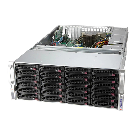
- Page 3 Preface Preface About This Manual This manual is written for professional system integrators and PC technicians. It provides information for the installation and use of the 6047R-E1CR36L. Installation and maintainance should be performed by experienced technicians only. The 6047R-E1CR36L is a high-end storage system based on the SC847BE1C- R1K28LPB 4U rackmountable chassis and the X9DRD-EF dual processor serverboard.
- Page 4 UPER TORAGE YSTEM 6047R-E1CR36L User's Manual Chapter 5: Advanced Serverboard Setup Chapter 5 provides detailed information on the X9DRD-EF serverboard, including the locations and functions of connections, headers and jumpers. Refer to this chapter when adding or removing processors or main memory and when reconfig- uring the serverboard.
- Page 5 Preface Notes...
-
Page 6: Table Of Contents
UPER TORAGE YSTEM 6047R-E1CR36L User's Manual Table of Contents Chapter 1 Introduction Overview ......................1-1 Serverboard Features ..................1-2 Processors ...................... 1-2 Memory ......................1-2 Serial ATA ......................1-2 PCI Expansion Slots ..................1-2 Rear I/O Ports ....................1-2 Rear I/O Ports ....................1-2 Server Chassis Features ................ - Page 7 Table of Contents NIC1 ........................ 3-2 NIC2 ........................ 3-3 HDD ......................... 3-3 Power ......................3-3 Drive Carrier LEDs ..................3-3 Chapter 4 Standardized Warning Statements for AC Systems About Standardized Warning Statements ............4-1 Warning Definition ................... 4-1 Installation Instructions ..................4-4 Circuit Breaker ....................
- Page 8 UPER TORAGE YSTEM 6047R-E1CR36L User's Manual Connector Definitions ................... 5-16 Jumper Settings .................... 5-23 5-10 Onboard Indicators ..................5-26 5-11 SATA Ports ....................5-27 5-12 Installing Software ..................5-28 SuperDoctor® 5 .................... 5-29 5-13 Onboard Battery .................... 5-30 Chapter 6 Advanced Chassis Setup Static-Sensitive Devices ..................
-
Page 9: Chapter 1 Introduction
Chapter 1: Introduction Chapter 1 Introduction Overview The 6047R-E1CR36L is a high-end storage system comprised of two main subsys- tems: the SC847BE1C-R1K28LPB 4U/rackmount chassis and the X9DRD-EF dual processor serverboard. Please refer to our web site for information on operating systems that have been certified for use with the system (www.supermicro.com). -
Page 10: Serverboard Features
UPER TORAGE YSTEM 6047R-E1CR36L User's Manual Serverboard Features The 6047R-E1CR36L is built around the X9DRD-EF, a dual processor serverboard based on the Intel C602J chipset. Below are the main features of the X9DRD-EF. (See Figure 1-1 for a block diagram of the chipset). Processors The X9DRD-EF supports single or dual Intel®... -
Page 11: Server Chassis Features
Chapter 1: Introduction Server Chassis Features The SC847BE1C-R1K28LPB is a 4U form factor chassis designed to be used in a storage configuration. The following is a general outline of the main features of the chassis. System Power The SC847BE1C-R1K28LPB features a redundant, hot-plug (two separate power modules) 1280W high-efficiency power supply with I C. - Page 12 UPER TORAGE YSTEM 6047R-E1CR36L User's Manual Figure 1-1. Intel C602J Chipset: System Block Diagram Note: This is a general block diagram. Please see Chapter 5 for details. (AB) (AB) (CD) CPU REAR Socket 01 PROCESSOR SANDYBRIDGE CPU FRONT Socket 00 PROCESSOR SANDYBRIDGE (AB)
- Page 13 Chapter 1: Introduction Figure 1-2. X9DRD-EF Serverboard VGA1 LAN2 LAN1 USB2/3 USB0/1 JUIDB COM2 COM1 JPW4 CTRL IPMI_LAN FAN8 FAN7 CPU2 JBAT1 JBT1 Battery CMOS CLEAR Intel JUSB6 X9DRD-EF BIOS Rev. 1.02 CPU1 JPW3 JPW2 BUZZER LED2 JPW1 FAN4 FAN1 FAN3 FAN2 FAN6...
-
Page 14: Contacting Supermicro
UPER TORAGE YSTEM 6047R-E1CR36L User's Manual Contacting Supermicro Headquarters Address: Super Micro Computer, Inc. 980 Rock Ave. San Jose, CA 95131 U.S.A. Tel: +1 (408) 503-8000 Fax: +1 (408) 503-8008 Email: marketing@supermicro.com (General Information) support@supermicro.com (Technical Support) Website: www.supermicro.com Europe Address: Super Micro Computer B.V. -
Page 15: Chapter 2 Server Installation
Chapter 2: Server Installation Chapter 2 Server Installation Overview This chapter provides a quick setup checklist to get your SuperServer 6047R- E1CR36L up and running. Following these steps in the order given should enable you to have the system operational within a minimum amount of time. This quick setup assumes that your system has come to you with the processors and memory preinstalled. -
Page 16: Rack Precautions
UPER TORAGE YSTEM 6047R-E1CR36L User's Manual • This product is for installation only in a Restricted Access Location (dedicated equipment rooms, service closets and the like). • This product is not suitable for use with visual display work place devices acccording to §2 of the the German Ordinance for Work with Visual Display Units. -
Page 17: Rack Mounting Considerations
Chapter 2: Server Installation Rack Mounting Considerations Ambient Operating Temperature If installed in a closed or multi-unit rack assembly, the ambient operating tempera- ture of the rack environment may be greater than the room's ambient temperature. Therefore, consideration should be given to installing the equipment in an environ- ment compatible with the manufacturer’s maximum rated ambient temperature (Tmra). -
Page 18: Rack Mounting Instructions
UPER TORAGE YSTEM 6047R-E1CR36L User's Manual Rack Mounting Instructions This section provides information on installing the chassis into a rack unit with the rails provided. There are a variety of rack units on the market, which may mean that the assembly procedure will differ slightly from the instructions provided. You should also refer to the installation instructions that came with the rack unit you are using. - Page 19 Chapter 2: Server Installation 3. Secure the rail to the chassis with four screws as illustrated. 4. Repeat steps 1-3 for the other inner rack rail. Locking Tabs Each inner rail has a locking tab. This tab locks the chassis into place when installed and pushed fully into the rack.
-
Page 20: Installing The Inner Rails On The Chassis
UPER TORAGE YSTEM 6047R-E1CR36L User's Manual Inner Rails Figure 2-3. Installing the Inner Rails Installing The Inner Rails on the Chassis Installing the Inner Rails 1. Confirm that the left and right inner rails have been correctly identified. Place the inner rail firmly against the side of the chassis, aligning the hooks on the side of the chassis with the holes in the inner rail. -
Page 21: Installing The Outer Rails Onto A Rack
Chapter 2: Server Installation L-min=676.00(26.61")(outer rail) 21D01 Figure 2-4. Extending and Releasing the Outer Rails Installing the Outer Rails on the Rack Installing the Outer Rails 1. Press upward on the locking tab at the rear end of the middle rail. 2. - Page 22 UPER TORAGE YSTEM 6047R-E1CR36L User's Manual Figure 2-5. Installing into a Rack Notes: figures are for illustrative purposes only. Always install servers into racks from the bottom up. The chassis pictured may vary slightly from the 6047R-E1CR36L system chassis. Stability hazard. The rack stabilizing mechanism must be in place, or the rack must be bolted to the floor before you slide the unit out for servicing.
-
Page 23: Chapter 3 System Interface
Chapter 3: System Interface Chapter 3 System Interface Overview There are several LEDs on the control panel as well as others on the drive carri- ers to keep you constantly informed of the overall status of the system as well as the activity and health of specific components. -
Page 24: Control Panel Leds
UPER TORAGE YSTEM 6047R-E1CR36L User's Manual Control Panel LEDs The control panel located on the front of the chassis has several LEDs. These LEDs provide you with critical information related to different parts of the system. This section explains what each LED indicates when illuminated and any corrective action you may need to take. -
Page 25: Nic2
Chapter 3: System Interface NIC2 Indicates network activity on the LAN2 port when flashing. Indicates IDE channel activity. On the SuperServer 6047R-E1CR36L, this LED indicates hard and/or DVD-ROM drive activity when flashing. Power Indicates power is being supplied to the system's power supply units. This LED should normally be illuminated when the system is operating. - Page 26 UPER TORAGE YSTEM 6047R-E1CR36L User's Manual Notes...
-
Page 27: About Standardized Warning Statements
Chapter 4: Warning Statements for AC Systems Chapter 4 Standardized Warning Statements for AC Systems About Standardized Warning Statements The following statements are industry standard warnings, provided to warn the user of situations which have the potential for bodily injury. Should you have questions or experience difficulty, contact Supermicro's Technical Support department for assistance. - Page 28 UPER TORAGE YSTEM 6047R-E1CR36L User's Manual Warnung WICHTIGE SICHERHEITSHINWEISE Dieses Warnsymbol bedeutet Gefahr. Sie befinden sich in einer Situation, die zu Verletzungen führen kann. Machen Sie sich vor der Arbeit mit Geräten mit den Gefahren elektrischer Schaltungen und den üblichen Verfahren zur Vorbeugung vor Unfällen vertraut.
- Page 29 Warning Statements for AC Systems جسذٌة اصابة ًتتسبب ف حالة ٌوكي أى ًاًك ف خطز ًٌٌع هذا الزهز !تحذٌز الذوائز بالوخاطز الٌاجوة عي ي على علن ، ك هعذات تعول على أي قبل أى الكهزبائٍة حىادث أي وقىع وٌع ل الىقائٍة...
-
Page 30: Installation Instructions
UPER TORAGE YSTEM 6047R-E1CR36L User's Manual Installation Instructions Warning! Read the installation instructions before connecting the system to the power source. 設置手順書 システムを電源に接続する前に、 設置手順書をお読み下さい。 警告 将此系统连接电源前,请先阅读安装说明。 警告 將系統與電源連接前,請先閱讀安裝說明。 Warnung Vor dem Anschließen des Systems an die Stromquelle die Installationsanweisungen lesen. ¡Advertencia! Lea las instrucciones de instalación antes de conectar el sistema a la red de alimentación. -
Page 31: Circuit Breaker
Chapter 4: Warning Statements for AC Systems Circuit Breaker Warning! This product relies on the building's installation for short-circuit (overcurrent) protection. Ensure that the protective device is rated not greater than: 250 V, 20 A. サーキッ ト ・ ブレーカー この製品は、 短絡 (過電流) 保護装置がある建物での設置を前提としています。 保護装置の定格が250 V、... -
Page 32: Power Disconnection Warning
UPER TORAGE YSTEM 6047R-E1CR36L User's Manual 경고! 이 제품은 전원의 단락(과전류)방지에 대해서 전적으로 건물의 관련 설비에 의존합니다. 보호장치의 정격이 반드시 250V(볼트), 20A(암페어)를 초과하지 않도록 해야 합니다. Waarschuwing Dit product is afhankelijk van de kortsluitbeveiliging (overspanning) van uw electrische installatie. Controleer of het beveiligde aparaat niet groter gedimensioneerd is dan 220V, 20A. - Page 33 Chapter 4: Warning Statements for AC Systems ¡Advertencia! El sistema debe ser disconnected de todas las fuentes de energía y del cable eléctrico quitado de los módulos de fuente de alimentación antes de tener acceso el interior del chasis para instalar o para quitar componentes de sistema. Attention Le système doit être débranché...
-
Page 34: Equipment Installation
UPER TORAGE YSTEM 6047R-E1CR36L User's Manual Equipment Installation Warning! Only trained and qualified personnel should be allowed to install, replace, or service this equipment. 機器の設置 トレーニングを受け認定された人だけがこの装置の設置、 交換、 またはサービスを許可 されています。 警告 只有经过培训且具有资格的人员才能进行此设备的安装、更换和维修。 警告 只有經過受訓且具資格人員才可安裝、更換與維修此設備。 Warnung Das Installieren, Ersetzen oder Bedienen dieser Ausrüstung sollte nur geschultem, qualifiziertem Personal gestattet werden. -
Page 35: Restricted Area
Chapter 4: Warning Statements for AC Systems Waarschuwing Deze apparatuur mag alleen worden geïnstalleerd, vervangen of hersteld door geschoold en gekwalificeerd personeel. Restricted Area Warning! This unit is intended for installation in restricted access areas. A restricted access area can be accessed only through the use of a special tool, lock and key, or other means of security. -
Page 36: Battery Handling
UPER TORAGE YSTEM 6047R-E1CR36L User's Manual אזור עם גישה מוגבלת !אזהרה יש להתקין את היחידה באזורים שיש בהם הגבלת גישה. הגישה ניתנת בעזרת .)'כלי אבטחה בלבד (מפתח, מנעול וכד محظورة مناطق ٍنتركُبها ف هذه انىحذة تخصيص تم ،أداة خاصت من خالل استخذاو فقط... - Page 37 Chapter 4: Warning Statements for AC Systems Warnung Bei Einsetzen einer falschen Batterie besteht Explosionsgefahr. Ersetzen Sie die Batterie nur durch den gleichen oder vom Hersteller empfohlenen Batterietyp. Entsorgen Sie die benutzten Batterien nach den Anweisungen des Herstellers. Attention Danger d'explosion si la pile n'est pas remplacée correctement. Ne la remplacer que par une pile de type semblable ou équivalent, recommandée par le fabricant.
-
Page 38: Redundant Power Supplies
UPER TORAGE YSTEM 6047R-E1CR36L User's Manual Redundant Power Supplies Warning! This unit might have more than one power supply connection. All connections must be removed to de-energize the unit. 冗長電源装置 このユニッ トは複数の電源装置が接続されている場合があります。 ユニッ トの電源を切るためには、 すべての接続を取り外さなければなりません。 警告 此部件连接的电源可能不止一个,必须将所有电源断开才能停止给该部件供电。 警告 此裝置連接的電源可能不只一個,必須切斷所有電源才能停止對該裝置的供電。 Warnung Dieses Gerät kann mehr als eine Stromzufuhr haben. -
Page 39: Backplane Voltage
Chapter 4: Warning Statements for AC Systems امداد الطاقة بوحدات عدة اتصاالت جهاز ال يكون لهذا قد الكهرباء عن وحدة ال لعسل كافة االتصاالت يجب إزالة 경고! 이 장치에는 한 개 이상의 전원 공급 단자가 연결되어 있을 수 있습니다. 이 장치에 전원을... -
Page 40: Comply With Local And National Electrical Codes
UPER TORAGE YSTEM 6047R-E1CR36L User's Manual מתח בפנל האחורי !הרה אז קיימת סכנת מתח בפנל האחורי בזמן תפעול המערכת. יש להיזהר במהלך .העבודה اللىحة أوالطاقة المىجىدة على التيار الكهزبائي مه خطز هناك هذا الجهاس خدمة كه حذرا عند يعمل النظام عندما... -
Page 41: Product Disposal
Chapter 4: Warning Statements for AC Systems Attention L'équipement doit être installé conformément aux normes électriques nationales et locales. תיאום חוקי החשמל הארצי !אזהרה הציוד חייבת להיות תואמת לחוקי החשמל המקומיים והארציים התקנת المتعلقة المحلية والىطىية قىاويه يجب أن يمتثل لل الكهربائية... -
Page 42: Hot Swap Fan Warning
UPER TORAGE YSTEM 6047R-E1CR36L User's Manual ¡Advertencia! Al deshacerse por completo de este producto debe seguir todas las leyes y reglamentos nacionales. Attention La mise au rebut ou le recyclage de ce produit sont généralement soumis à des lois et/ou directives de respect de l'environnement. Renseignez-vous auprès de l'organisme compétent. - Page 43 Chapter 4: Warning Statements for AC Systems 警告 當您從機架移除風扇裝置,風扇可能仍在轉動。小心不要將手指、螺絲起子和其他 物品太靠近風扇。 Warnung Die Lüfter drehen sich u. U. noch, wenn die Lüfterbaugruppe aus dem Chassis genommen wird. Halten Sie Finger, Schraubendreher und andere Gegenstände von den Öffnungen des Lüftergehäuses entfernt. ¡Advertencia! Los ventiladores podran dar vuelta cuando usted quite ell montaje del ventilador del chasis.
-
Page 44: Power Cable And Ac Adapter
UPER TORAGE YSTEM 6047R-E1CR36L User's Manual Power Cable and AC Adapter Warning! When installing the product, use the provided or designated connection cables, power cables and AC adaptors. Using any other cables and adaptors could cause a malfunction or a fire. Electrical Appliance and Material Safety Law prohibits the use of UL or CSA -certified cables (that have UL/CSA shown on the code) for any other electrical devices than products designated by Supermicro only. - Page 45 Chapter 4: Warning Statements for AC Systems Attention Lors de l'installation du produit, utilisez les bables de connection fournis ou désigné. L'utilisation d'autres cables et adaptateurs peut provoquer un dysfonctionnement ou un incendie. Appareils électroménagers et de loi sur la sécurité Matériel interdit l'utilisation de UL ou CSA câbles certifiés qui ont UL ou CSA indiqué...
- Page 46 UPER TORAGE YSTEM 6047R-E1CR36L User's Manual Notes 4-20...
-
Page 47: Chapter 5 Advanced Serverboard Setup
Chapter 5: Advanced Serverboard Setup Chapter 5 Advanced Serverboard Setup This chapter covers the steps required to install the X9DRD-EF serverboard into the chassis, connect the data and power cables and install add-on cards. All serverboard jumpers and connections are also described. A layout and quick reference chart are included in this chapter for your reference. -
Page 48: Unpacking
UPER TORAGE YSTEM 6047R-E1CR36L User's Manual Unpacking The serverboard is shipped in antistatic packaging to avoid electrical static dis- charge. When unpacking the board, make sure the person handling it is static protected. Connecting Cables Several cables need to be connected to the serverboard. These include the data cables for the peripherals and control panel and the power cables. -
Page 49: Rear I/O Ports
Chapter 5: Advanced Serverboard Setup Figure 5-1. Control Panel Header Pins Ground FP PWRLED 3.3 V ID_UID_SW/3/3V Stby HDD LED NIC1 Link LED NIC1 Activity LED NIC2 Activity LED NIC2 Link LED Blue+ (OH/Fan Fail/ Red+ (Blue LED Cathode) PWR FaiL/UID LED) Power Fail LED 3.3V Reset... -
Page 50: Installing The Processor And Heatsink
UPER TORAGE YSTEM 6047R-E1CR36L User's Manual Installing the Processor and Heatsink Warning: When handling the processor package, avoid placing direct pressure on the label area of the fan. Notes: • Always connect the power cord last and always remove it before adding, re- moving or changing any hardware components. - Page 51 Chapter 5: Advanced Serverboard Setup 3. With the lever labeled 'Close 1st' fully retracted, gently push down on the 'Open 1st' lever to open the load plate. Lift the load plate to open it completely. Gently push 4. Using your thumb and the index down to pop the load plate finger, remove the 'WARNING'...
- Page 52 UPER TORAGE YSTEM 6047R-E1CR36L User's Manual Warning: You can only install the CPU to the socket in one direction. Make sure that the CPU is properly inserted into the socket before closing the load plate. If it doesn't close properly, do not force it as it may damage your CPU. Instead, open the load plate again and double-check that the CPU is aligned properly.
-
Page 53: Installing A Passive Cpu Heatsink
Chapter 5: Advanced Serverboard Setup Installing a Passive CPU Heatsink 1. Do not apply any thermal grease to the heatsink or the CPU die; the required amount has already been applied. 2. Place the heatsink on top of the CPU so that the four mounting holes are aligned with those on the Serverboard's and the Heatsink Bracket underneath. -
Page 54: Installing Memory
UPER TORAGE YSTEM 6047R-E1CR36L User's Manual Installing Memory Caution: Exercise extreme care when installing or removing DIMM modules to prevent any possible damage. Memory Support The X9DRD-EF supports up to 71 TB of Load Reduced (LRDIMM), 512 GB of Registered (RDIMM) or 128 GB of Unbuffered (UDIMM) ECC/Non-ECC DDR3- 800/1066/1333/1600/1866 memory. - Page 55 Chapter 5: Advanced Serverboard Setup Processor & Memory Module Population Configuration For memory to work properly, follow the tables below for memory installation. Processors and their Corresponding Memory Modules CPU# Corresponding DIMM Modules CPU 1 DIMMA1 DIMMB1 DIMMC1 DIMMD1 DIMMA2 DIMMB2 DIMMC2 DIMMD2...
- Page 56 UPER TORAGE YSTEM 6047R-E1CR36L User's Manual Populating UDIMM (ECC/Non-ECC) Memory Modules Intel E5-2600(v2) Series Processor UDIMM Memory Support Ranks Memory Capacity Speed (MT/s) and Voltage Validated by Slot per Channel (SPC) and Per DIMM DIMM Per Channel (DPC) DIMM 2 Slots Per Channel 3 Slots Per Channel &...
- Page 57 Chapter 5: Advanced Serverboard Setup Populating UDIMM (ECC/Non-ECC) Memory Modules Intel E5-2600 Series Processor UDIMM Memory Support Ranks Memory Capacity Speed (MT/s) and Voltage Validated by Slot per Channel (SPC) and Per DIMM DIMM Per Channel (DPC) DIMM 2 Slots Per Channel 3 Slots Per Channel &...
- Page 58 UPER TORAGE YSTEM 6047R-E1CR36L User's Manual Populating LRDIMM (ECC) Memory Modules Intel E5-2600(v2) Series Processor LRDIMM Memory Support Ranks Memory Speed (MT/s) and Voltage Validated by Slot per Channel (SPC) and DIMM Per Capacity Channel (DPC) DIMM Per DIMM 2 Slots Per Channel 3 Slots Per Channel &...
-
Page 59: Adding Pci Add-On Cards
Chapter 5: Advanced Serverboard Setup Adding PCI Add-On Cards The 6047R-E1CR36L can accommodate up to four PCI add-on cards. Installing an Add-on Card 1. Begin by removing the shield for the PCI slot you wish to populate. 2. Fully seat the card into the slot, pushing down with your thumbs evenly on both sides of the card. -
Page 60: Serverboard Details
UPER TORAGE YSTEM 6047R-E1CR36L User's Manual Serverboard Details Figure 5-5. X9DRD-EF Layout VGA1 LAN2 LAN1 USB2/3 USB0/1 JUIDB COM2 COM1 JPW4 CTRL IPMI_LAN FAN8 FAN7 CPU2 JBAT1 JBT1 Battery CMOS CLEAR Intel JUSB6 X9DRD-EF BIOS Rev. 1.02 CPU1 JPW3 JPW2 BUZZER LED2 JPW1... - Page 61 Chapter 5: Advanced Serverboard Setup Jumper Description Default Setting Clear CMOS See Section 5-9 JBT1 SMB to PCI-E Slots Enable/Disable Open (Disabled) C1/JI JPB1 BMC Enable/Disable Pins 1-2 (Enabled) JPG1 VGA Enable/Disable Pins 1-2 (Enabled) JPL1 GLAN1/GLAN2 Enable/Disable Pins 1-2 (Enabled) JPME1 Management Engine (ME) Recovery Mode Pins 1-2 (Normal)
-
Page 62: Connector Definitions
UPER TORAGE YSTEM 6047R-E1CR36L User's Manual Connector Definitions ATX Power 24-pin Connector Pin Definitions Pin# Definition Pin # Definition Power Connectors +3.3V +3.3V -12V +3.3V A 24-pin main power supply connec- tor (JPW1) and two 8-pin CPU power PS_ON connectors (JPW2/3) and a 4-pin connector (JPW4) must be connected to the power supply. - Page 63 Chapter 5: Advanced Serverboard Setup Power Fail LED PWR Fail LED Pin Definitions (JF1) The Power Fail LED connection is Pin# Definition located on pins 5 and 6 of JF1. Re- 3.3V fer to the table on the right for pin Signal definitions.
- Page 64 UPER TORAGE YSTEM 6047R-E1CR36L User's Manual Power On LED Power LED Pin Definitions (JF1) The Power LED connector is located Pin# Definition on pins 15 and 16 of JF1. This con- 3.3V nection is used to provide LED indica- Signal tion of power being supplied to the system.
- Page 65 Chapter 5: Advanced Serverboard Setup LAN Ports Pin Definition Pin# Definition P2V5SB SGND Ethernet Ports TD0+ Act LED Four Ethernet ports are located on the TD0- P3V3SB I/O backplane. A dedicated IPMI LAN TD1+ Link 100 LED (Yel- low, +3V3SB) port is also included to provide KVM TD1- Link 1000 LED...
- Page 66 UPER TORAGE YSTEM 6047R-E1CR36L User's Manual Serial Port Pin Definitions Serial Ports (COM1/COM2) Pin # Definition Pin # Definition Two serial ports are included on the serverboard. COM1 is a backpanel port and COM2 is a header located near the PCI-E slot 1. See the table on the right for pin definitions.
- Page 67 Chapter 5: Advanced Serverboard Setup Standby Power Header Standby PWR Pin Definitions A +5V Standby Power header is lo- Pin# Definition cated at JSTBY1 on the serverboard. +5V Standby See the table on the right for pin defini- Ground tions. (You must also have a card with Wake-up a Standby Power connector and a cable to use this feature.)
- Page 68 UPER TORAGE YSTEM 6047R-E1CR36L User's Manual TPM/Port 80 Header Pin Definitions Pin # Definition Pin # Definition TPM Header/Port 80 LCLK A Trusted Platform Module/Port 80 LFRAME# <(KEY)> header is located at JTPM1 to provide LRESET# +5V (X) TPM support and a Port 80 connec- LAD 3 LAD 2 tion.
-
Page 69: Jumper Settings
Chapter 5: Advanced Serverboard Setup Jumper Settings Explanation of Jumpers To modify the operation of the serverboard, jumpers can be used Connector to choose between optional settings. Pins Jumpers create shorts between two pins to change the function of the con- nector. - Page 70 UPER TORAGE YSTEM 6047R-E1CR36L User's Manual GLAN Enable/Disable GLAN Enable Jumper Settings JPL1 enables or disables the GLAN Jumper Setting Definition ports on the serverboard. See the Pins 1-2 Enabled table on the right for jumper settings. Pins 2-3 Disabled C Bus to PCI-Exp.
- Page 71 Chapter 5: Advanced Serverboard Setup ME Recovery Close jumper JPME1 to use ME Firm- ware Recovery mode, which will limit ME Recovery Jumper Settings system activities to support essential Jumper Setting Definition functions only. There will be no power Pins 1-2 Normal use restrictions.
-
Page 72: 5-10 Onboard Indicators
X8DT3/i-F/-LN4F UPER TORAGE YSTEM 6047R-E1CR36L User's Manual X8DT3-LN4/LN4F 5-10 Onboard Indicators LAN LEDs The Ethernet ports (located beside the JLAN1/2 LED VGA port) have two LEDs. On each (Connection Speed Indicator) port, the yellow LED flashes to indi- LED Color Definition cate activity while the other LED may NC or 10 Mbps... -
Page 73: 5-11 Sata Ports
Chapter 5: Advanced Serverboard Setup 5-11 SATA Ports Serial ATA Ports SATA Port There are six SATA ports located Pin Definitions on the serverboard, including four Pin# Definition Definition SATA2 ports and two SATA3 ports. Ground These ports provide serial-link signal Ground connections, which are faster than Parallel ATA. -
Page 74: 5-12 Installing Software
UPER TORAGE YSTEM 6047R-E1CR36L User's Manual 5-12 Installing Software The Supermicro ftp site contains drivers and utilities for your system at ftp://ftp. supermicro.com. Some of these must be installed, such as the chipset driver. After accessing the ftp site, go into the CDR_Images directory and locate the ISO file for your serverboard. -
Page 75: Superdoctor® 5
Chapter 5: Advanced Serverboard Setup SuperDoctor® 5 The Supermicro SuperDoctor 5 is a program that functions in a command-line or web-based interface in Windows and Linux operating systems. The program moni- tors system health information such as CPU temperature, system voltages, system power consumption, fan speed, and provides alerts via email or Simple Network Management Protocol (SNMP). -
Page 76: 5-13 Onboard Battery
UPER TORAGE YSTEM 6047R-E1CR36L User's Manual 5-13 Onboard Battery Please handle used batteries carefully. Do not damage the battery in any way; a damaged battery may release hazardous materials into the environment. Do not discard a used battery in the garbage or a public landfill. Please comply with the regulations set up by your local hazardous waste management agency to dispose of your used battery properly. -
Page 77: Chapter 6 Advanced Chassis Setup
Chapter 6: Advanced Chassis Setup Chapter 6 Advanced Chassis Setup This chapter covers the steps required to install components and perform mainte- nance on the SC847BE1C-R1K28LPB chassis. For component installation, follow the steps in the order given to eliminate the most common problems encountered. If some steps are unnecessary, skip ahead to the step that follows. -
Page 78: Control Panel
UPER TORAGE YSTEM 6047R-E1CR36L User's Manual Figure 6-1. Front and Rear Chassis Views Control Panel Hard Drives (24) JBOD Expansion Ports Power Supplies (2) Hardware RAID Add-on Card I/O Ports Optional 2.5" Hot-swap Hard Drives (12) Drive Bay Control Panel The control panel (located on the front of the chassis) must be connected to the JF1 connector on the serverboard to provide you with system status indications. -
Page 79: Removing The Chassis Cover
Chapter 6: Advanced Chassis Setup Removing the Chassis Cover Figure 6-2. Removing the Chassis Cover Removing the Chassis Cover 1. Unplug the chassis from any power source 2. Remove the screws securing the cover to the chassis. 3. Lift the cover up and off the chassis. Warning: Except for short periods of time, do NOT operate the server without the cover in place. -
Page 80: System Fans
UPER TORAGE YSTEM 6047R-E1CR36L User's Manual System Fans Seven 8-cm hot-swap chassis fans provide redundant cooling for the SuperServer 6047R-E1CR36L. It is very important that the chassis top cover is properly installed and making a good seal in order for the cooling air to circulate properly through the chassis and cool the components. -
Page 81: Drive Bay Installation/Removal
Chapter 6: Advanced Chassis Setup Figure 6-3. Replacing System Cooling Fans Drive Bay Installation/Removal Accessing the Drive Bays SATA Drives: You do not need to access the inside of the chassis or remove power to replace or swap SATA drives. Proceed to the next step for instructions. Note: You must use standard 1"... -
Page 82: Hard Drive Installation
UPER TORAGE YSTEM 6047R-E1CR36L User's Manual Hard Drive Installation Mounting a Hard Drive in a Drive Carrier The SATA drives are mounted in drive carriers to simplify their installation and removal from the chassis. These carriers also help promote proper airflow for the drives, so empty carriers without drives installed must also remain in the chassis. -
Page 83: Hard Drive Backplane
Chapter 6: Advanced Chassis Setup Figure 6-4. Mounting a Drive in a Carrier Figure 6-5. Installing a Drive Carrier Hard Drive Backplane The hard drives plug into a backplane that provides power, drive ID and bus termi- nation. The supplied RAID controller provides hot-swap capability with SATA drive state indication. -
Page 84: Removing The Air Shroud
UPER TORAGE YSTEM 6047R-E1CR36L User's Manual Removing the Air Shroud Under most circumstances you will not need to remove the air shroud to perform any service on the system. However, if you need to temporarily remove it (the air shroud sould always be in place when the system is operating), please follow this procedure. -
Page 85: Installing Optional Fixed Hard Drives
Chapter 6: Advanced Chassis Setup Installing Optional Fixed Hard Drives The SC847 chassis includes brackets for installing either one 3.5" fixed hard drive, or two 2.5" fixed hard drives within the chassis. Each chassis can accomodate up to two internal drive trays supporting up to two 3.5" hard drives or up to four 2.5" hard drives. -
Page 86: Power Supply
UPER TORAGE YSTEM 6047R-E1CR36L User's Manual Power Supply The SuperServer 6047R-E1CR36L has an 1280 watt redundant, hot-plug power supply consisting of two power modules. Each power supply module has an auto- switching capability, which enables it to automatically sense and operate at a 100V - 240V input voltage. -
Page 87: Dc Power
Chapter 6: Advanced Chassis Setup DC Power The AC power supplies may be removed and replaced with a DC power supply. Replacing the AC Power Supply with a DC Power Supply 1. Shut down the system and unplug the AC power cord. 2. - Page 88 UPER TORAGE YSTEM 6047R-E1CR36L User's Manual Figure 6-8. JBOD Expansion Port JBOD OUT (downstream ports) Note: the use of two cables (8x SAS lanes) is recommended. 6-12...
-
Page 89: Chapter 7 Bios
Chapter 7: BIOS Chapter 7 BIOS Introduction This chapter describes the AMI BIOS Setup utility for the X9DRD-EF/7LN4F- JBOD/7LN4F. It also provides the instructions on how to navigate the AMI BIOS Setup utility screens. The AMI ROM BIOS is stored in a Flash EEPROM and can be easily updated. -
Page 90: Main Setup
UPER TORAGE YSTEM 6047R-E1CR36L User's Manual How To Change the Configuration Data The configuration data that determines the system parameters may be changed by entering the AMI BIOS Setup utility. This Setup utility can be accessed by pressing <Delete> at the appropriate time during system boot. Note: For AMI UEFI BIOS Recovery, please refer to the UEFI BIOS Recov- ery User Guide posted @ http://www.supermicro.com/support/manuals/. - Page 91 Chapter 7: BIOS System Date/System Time Use this option to change the system time and date. Highlight System Time or System Date using the arrow keys. Enter new values through the keyboard and press <Enter>. Press the <Tab> key to move between fields. The date must be entered in Day MM/DD/YY format.
-
Page 92: Advanced Setup Configurations
UPER TORAGE YSTEM 6047R-E1CR36L User's Manual Advanced Setup Configurations Select the Advanced tab to access the following submenu items. Boot Feature Quiet Boot This feature allows the user to select bootup screen display between POST mes- sages and the OEM logo. Select Disabled to display the POST messages. Select Enabled to display the OEM logo instead of the normal POST messages. - Page 93 Chapter 7: BIOS at bootup and allow the drives that are attached to these host adaptors to function as bootable disks. If this item is set to Disabled, the ROM BIOS of the host adap- tors will not capture Interrupt 19, and the drives attached to these adaptors will not function as bootable devices.
- Page 94 UPER TORAGE YSTEM 6047R-E1CR36L User's Manual • Processor Cores • Intel HT (Hyper-Threading) Technology • Intel VT-x Technology • Intel SMX Technology • L1 Data Cache / L1 Code Cache • L2 Cache • L3 Cache CPU Speed This item displays the speed of the CPU installed in Socket 1/Socket 2. 64-bit This item indicates if the CPU installed in Socket 1 or Socket 2 supports 64-bit technology.
- Page 95 Chapter 7: BIOS Execute-Disable Bit (Available if supported by the OS & the CPU) Select Enabled to enable the Execute Disable Bit which will allow the processor to designate areas in the system memory where an application code can execute and where it cannot, thus preventing a worm or a virus from flooding illegal codes to overwhelm the processor or damage the system during an attack.
- Page 96 UPER TORAGE YSTEM 6047R-E1CR36L User's Manual CPU Power Management Configuration This submenu allows the user to configure the following CPU Power Manage- ment settings. Power Technology Select Energy Efficiency to support power-saving mode. Select Custom to cus- tomize system power settings. Select Disabled to disable power-saving settings. The options are Disabled, Energy Efficient, and Custom.
- Page 97 Chapter 7: BIOS Package C-State limit (Available when Power Technology is set to Custom) This feature allows the user to set the limit on the C-State package register. The options are C0, C2, C6, and No Limit. Energy/Performance Bias Use this feature to select an appropriate fan setting to achieve maximum system performance (with maximum cooling) or maximum energy efficiency with maxi- mum power saving).
- Page 98 UPER TORAGE YSTEM 6047R-E1CR36L User's Manual Chipset Configuration North Bridge This feature allows the user to configure the settings for the Intel North Bridge. Integrated IO Configuration Intel VT-d ® Select Enabled to enable Intel Virtualization Technology support for Direct I/O VT-d by reporting the I/O device assignments to the VMM (Virtual Machine Monitor) through the DMAR ACPI Tables.
- Page 99 Chapter 7: BIOS IIO 2 PCIe Port Bifurcation Control This submenu configures the following IO PCIe Port Bifurcation Control settings for IIO 2 PCIe ports to determine how the available PCI-Express lanes to be distributed between the PCI-Exp. Root ports. QPI Configuration Current QPI Link This item displays the current status of the QPI Link.
- Page 100 UPER TORAGE YSTEM 6047R-E1CR36L User's Manual DIMM Information CPU Socket 1 DIMM Information, CPU Socket 2 DIMM Information The status of the memory modules detected by the BIOS will be displayed as detected by the BIOS. Memory Mode When Independent is selected, all DIMMs are available to the operating system. When Mirroring is selected, the motherboard maintains two identical copies of all data in memory for data backup.
- Page 101 Chapter 7: BIOS correctable error, the error is corrected and sent to the requestor (the original source). Memory is updated as well. Select Enabled to use Demand Scrubbing for ECC memory correction. The options are Enabled and Disabled. Data Scrambling Select Enabled to enable data scrambling to ensure data security and integrity.
- Page 102 UPER TORAGE YSTEM 6047R-E1CR36L User's Manual Port 60/64 Emulation Select Enabled to enable I/O port 60h/64h emulation support for the legacy USB keyboard so that it can be fully supported by the operating systems that does not recognize a USB device. The options are Disabled and Enabled. EHCI Hand-Off This item is for operating systems that do not support Enhanced Host Controller Interface (EHCI) hand-off.
- Page 103 Chapter 7: BIOS Port 0~5 Hot Plug Select Enabled to enable hot-plug support for a particular port, which will allow the user to change a hardware component or device without shutting down the system. The options are Enabled and Disabled. Staggered Spin Up Select Enabled to enable Staggered Spin-up support to prevent excessive power consumption caused by multiple HDDs spinning-up simultaneously.
- Page 104 UPER TORAGE YSTEM 6047R-E1CR36L User's Manual SERR# Generation Select Enabled to allow a PCI device to generate an SERR number for a PCI Bus Signal Error Event. The options are Enabled and Disabled. Maximum Payload Select Auto to allow the system BIOS to automatically set the maximum payload value for a PCI-E device to enhance system performance.
- Page 105 Chapter 7: BIOS VGA Priority This feature allows the user to select the graphics adapter to be used as the primary boot device. The options are Onboard, and Offboard. Network Stack Select Enabled enable PXE (Preboot Execution Environment) or UEFI (Unified Extensible Firmware Interface) for network stack support.
- Page 106 UPER TORAGE YSTEM 6047R-E1CR36L User's Manual Change Settings This option specifies the base I/O port address and the Interrupt Request address of Serial Port 2. Select Disabled to prevent the serial port from accessing any system resources. When this option is set to Disabled, the serial port becomes unavailable. The options are Auto, IO=3F8h;...
- Page 107 Chapter 7: BIOS client computer. A lower transmission speed may be required for long and busy lines. The options are 9600, 19200, 38400, 57600 and 115200 (bits per second). Data Bits Use this feature to set the data transmission size for Console Redirection. The options are 7 Bits and 8 Bits.
- Page 108 UPER TORAGE YSTEM 6047R-E1CR36L User's Manual Putty KeyPad This feature selects Function Keys and KeyPad settings for Putty, which is a terminal emulator designed for the Windows OS. The options are VT100, LINUX, XTERMR6, SC0, ESCN, and VT400. Serial Port for Out-of-Band Management/Windows Emergency Management Services (EMS) The submenu allows the user to configure Console Redirection settings to support Out-of-Band Serial Port management.
- Page 109 Chapter 7: BIOS Data Bits, Parity, Stop Bits The status of these features is displayed. ACPI Settings Use this feature to configure Advanced Configuration and Power Interface (ACPI) power management settings for your system. ACPI Sleep State Use this feature to select the ACPI State when the system is in sleep mode. Select S1 (CPU_Stop_Clock) to erase all CPU caches and stop executing instructions.
- Page 110 UPER TORAGE YSTEM 6047R-E1CR36L User's Manual Pending Operation Use this item to schedule an operation for the security device. The options are None, Enable Take Ownership, Disable Take Ownership, and TPM Clear. Note: During restart, the computer will reboot in order to execute the pend- ing operation and change the state of the security device.
- Page 111 Chapter 7: BIOS TPM Support: Trusted Platform support TPM State: Trusted Platform state ME Subsystem This feature displays the following ME Subsystem Configuration settings. • ME BIOS Interface Version • ME Version iSCSI Configuration: This item displays iSCSI configuration information: iSCSI Initiator Name This item displays the name of the iSCSI Initiator, which is a unique name used in the world.
- Page 112 UPER TORAGE YSTEM 6047R-E1CR36L User's Manual Blink LEDs This feature allows the user to specify the duration for LEDs to blink. The range is from 0 ~ 15 seconds. The default setting is 0. PORT CONFIGURATION INFORMATION This section displays the following port information: •...
-
Page 113: Event Logs
Chapter 7: BIOS Event Logs Select the Event Logs tab to access the following submenu items. Change SMBIOS Event Log Settings This feature allows the user to configure SMBIOS Event settings. Enabling/Disabling Options SMBIOS Event Log Select Enabled to enable SMBIOS (System Management BIOS) Event Logging during system boot. - Page 114 UPER TORAGE YSTEM 6047R-E1CR36L User's Manual Erasing Settings Erase Event Log Select Enabled to erase the SMBIOS (System Management BIOS) Event Log, which is completed before a event logging is initialized upon system reboot. The options are No, Yes, Next reset, and Yes, Every reset. When Log is Full Select Erase Immediately to immediately erase SMBIOS error event logs that ex- ceed the limit when the SMBIOS event log is full.
-
Page 115: Ipmi
Chapter 7: BIOS IPMI Select the IPMI (Intelligent Platform Management Interface) tab to access the fol- lowing submenu items. IPMI Firmware Revision This item indicates the IPMI firmware revision used in your system. IPMI Status This item indicates the status of the IPMI firmware installed in your system. System Event Log ... - Page 116 UPER TORAGE YSTEM 6047R-E1CR36L User's Manual When SEL is Full This feature allows the user to decide what the BIOS should do when the system event log is full. Select Erase Immediately to erase all events in the log when the system event log is full.
-
Page 117: Boot
Chapter 7: BIOS Gateway IP Address This item displays the Gateway IP address for this computer. This should be in decimal and in dotted quad form (i.e., 192.168.10.253). Boot This submenu allows the user to configure the following boot settings for the system. -
Page 118: Security
UPER TORAGE YSTEM 6047R-E1CR36L User's Manual Security This menu allows the user to configure the following security settings for the system. Password Check Use this feature to determine when a password entry is required. Select Setup to require the password only when entering setup. Select Always to require the pass- word when entering setup and on each boot. -
Page 119: Save & Exit
Chapter 7: BIOS Save & Exit This submenu allows the user to configure the Save and Exit settings for the system. Discard Changes and Exit Select this option to quit the BIOS Setup without making any permanent changes to the system configuration, and reboot the computer. Select Discard Changes and Exit, and press <Enter>. - Page 120 UPER TORAGE YSTEM 6047R-E1CR36L User's Manual Discard Changes Select this feature and press <Enter> to discard all the changes and return to the BIOS setup. When the dialog box appears, asking you if you want to load previ- ous values, select Yes to load the values previous saved, or select No to keep the changes you've made so far.
-
Page 121: Appendix A Bios Post Error Codes
Appendix A: BIOS POST Error Codes Appendix A BIOS POST Error Codes During the POST (Power-On Self-Test) routines, which are performed at each system boot, errors may occur. Non-fatal errors are those which, in most cases, allow the system to continue to boot. - Page 122 UPER TORAGE YSTEM 6047R-E1CR36L User's Manual Notes...
-
Page 123: Appendix B System Specifications
Appendix B: System Specifications Appendix B System Specifications Processors Single or dual Intel® Xeon E5-2600 (v2) Series processors Note: Please refer to our web site for a complete listing of supported processors. Chipset Intel C602J chipset BIOS 16 Mb AMI® SPI Flash ROM Memory Capacity Sixteen DIMM sockets supporting up to 1 TB of Load Reduced (LRDIMM), 512 GB of Registered (RDIMM) or 128 GB of Unbuffered (UDIMM) ECC/Non-ECC... - Page 124 UPER TORAGE YSTEM 6047R-E1CR36L User's Manual Weight Net: 78 lbs. (35.5 kg.) Gross: 110 lbs. (220 kg.) System Cooling Four 8-cm system fans Three 8-cm exhaust fans One air shroud Power Supply Rated Output Power: 1280W (Part# PWS-1K28P-SQ) Rated Output Voltages: 1000W: +12V (83A), +5Vsb (4A), 1280W: +12V (106.7A), +5Vsb (4A) System Input Requirements AC Input Voltage: 100 - 240V AC auto-range...
- Page 125 Appendix B: System Specifications Notes...
- Page 126 UPER TORAGE YSTEM 6047R-E1CR36L User's Manual (continued from front) The products sold by Supermicro are not intended for and will not be used in life support systems, medical equipment, nuclear facilities or systems, aircraft, aircraft devices, aircraft/emergency com- munication devices or other critical systems whose failure to perform be reasonably expected to result in significant injury or loss of life or catastrophic property damage.
Need help?
Do you have a question about the SUPER STORAGE SYSTEM 6047R-E1CR36L and is the answer not in the manual?
Questions and answers