Bender LINETRAXX VMD461 Manual
Multifunctional voltage relay with coupling device cd440 for dc, 1ac, 3(n)ac systems
Hide thumbs
Also See for LINETRAXX VMD461:
- Quick start manual (8 pages) ,
- Quick start manual (13 pages)
Table of Contents
Advertisement
Quick Links
Manual
VMD461
LINETRAXX®
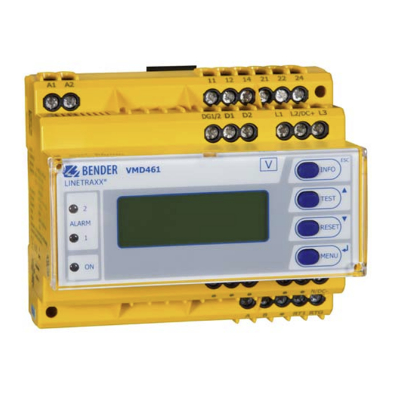
Multifunctional voltage relay for DC, 1AC, 3(N)AC systems
Underfrequency 81<U*, overfrequency 81>O*, overvoltage 59*,
undervoltage 27*, phase sequence 47*, unbalance 47*, vector shift 78*,
ROCOF df/dt 81R*
* ANSI codes
Software version, measurement technology: D570 V1.2x
Software version, display: D256 V2.3x
VMD461_D00314_01_M_XXEN/10.2018
with coupling device CD440
Advertisement
Table of Contents

Related Manuals for Bender LINETRAXX VMD461


Summary of Contents for Bender LINETRAXX VMD461
- Page 1 Manual VMD461 with coupling device CD440 LINETRAXX® Multifunctional voltage relay for DC, 1AC, 3(N)AC systems Underfrequency 81<U*, overfrequency 81>O*, overvoltage 59*, undervoltage 27*, phase sequence 47*, unbalance 47*, vector shift 78*, ROCOF df/dt 81R* * ANSI codes Software version, measurement technology: D570 V1.2x Software version, display: D256 V2.3x VMD461_D00314_01_M_XXEN/10.2018...
- Page 2 Bender GmbH & Co. KG P.O. Box 1161 • 35301 Gruenberg • Germany Londorfer Strasse 65 • 35305 Gruenberg • Germany Tel.: +49 6401 807-0 • Fax: +49 6401 807-259 E-Mail: info@bender.de • www.bender.de © Bender GmbH & Co. KG All rights reserved.
-
Page 3: Table Of Contents
Table of Contents 1. Important information ..................7 How to use this manual ................. 7 Technical support: service and support ........... 8 1.2.1 First level support ..................... 8 1.2.2 Repair service ..................... 8 1.2.3 Field service ......................9 Training courses ..................... 10 Delivery conditions .................. - Page 4 Table of Contents Mounting on DIN rail ..................22 Screw mounting .................... 23 4.8.1 VMD461 ......................23 4.8.2 CD440 ........................ 23 Wiring diagram ....................24 4.9.1 DC: VMD461 with CD440 ................25 4.9.2 AC: VMD461 with CD440 (earthed system) ......... 26 4.9.3 AC: VMD461 with CD440 (unearthed system) ........
- Page 5 Table of Contents 6.3.3 Menu structure "3. Settings" ..............45 6.3.4 Explanatory comments on individual menu items ......52 Menu "4. System" ................... 62 6.4.1 Menu structure "4. System" ............... 62 6.4.2 Explanatory comments on individual menu items ......64 Menu "5.
-
Page 7: Important Information
This manual has been compiled with great care. It might nevertheless contain errors and mistakes. Bender cannot accept any liability for injury to persons or damage to property resulting from errors or mistakes in this manual. -
Page 8: Technical Support: Service And Support
0700BenderHelp (Tel. and Fax) E-mail: support@bender-service.de 1.2.2 Repair service Repair, calibration, update and replacement service for Bender products Repairing, calibrating, testing and analysing Bender products Hardware and software update for Bender devices Delivery of replacement devices in the event of faulty or incorrectly ... -
Page 9: Field Service
Important information 1.2.3 Field service On-site service for all Bender products Commissioning, configuring, maintenance, troubleshooting for Bender products Analysis of the electrical installation in the building (power quality test, EMC test, thermography) Training courses for customers ... -
Page 10: Training Courses
ZVEI (Zentralverband Elektrotechnik- und Elektronikindustrie e. V.) (German Electrical and Electron- ic Manufacturer's Association) also applies. Sale and delivery conditions can be obtained from Bender in printed or elec- tronic format. 1.5 Inspection, transport and storage Inspect the dispatch and equipment packaging for damage, and compare the contents of the package with the delivery documents. -
Page 11: Warranty And Liability
Important information 1.6 Warranty and liability Warranty and liability claims in the event of injury to persons or damage to property are excluded if they can be attributed to one or more of the follow- ing causes: Improper use of the device. ... -
Page 12: Disposal
13 August 2005 must be taken back by the manufacturer and disposed of properly. For more information on the disposal of Bender devices, refer to our website at www.bender-de.com -> Service & support. -
Page 13: Safety Instructions
2. Safety instructions 2.1 General safety instructions Part of the device documentation in addition to this manual is the enclosed "Safety instructions for Bender products". 2.2 Work activities on electrical installations Only qualified personnel are permitted to carry out the work necessary to install, commission and run a device or system. -
Page 14: Intended Use
Safety instructions 2.3 Intended use The multifunctional voltage monitoring relay VMD461 monitors frequencies, undervoltages and overvoltages in DC, AC and 3(N)AC systems. The phase voltages and/or line-to-line voltages are measured as r.m.s. value and are con- tinuously shown on the device display. The measured value required to trig- ger the alarm relay is stored. -
Page 15: Function
3. Function 3.1 Device features When combined with a CD440 coupling device, DC systems up to 1200 V, 1AC systems up to 690 V, 3AC systems up to 1200 V and 3NAC systems up to 690 V can be monitored All functions are represented in ANSI codes ... -
Page 16: Glossary
Function 3.2 Glossary Terms Description Start-up delay start-up Once the supply voltage is applied, the start-up delay begins. Measured voltage and frequency val- start-up ues changing during this time do not influence the switching state of the alarm relays K1 and K2. At that moment, the switching state of the alarm relays K1 and K2 depends on the "Start alarm"... -
Page 17: Functional Description
Function 3.3 Functional description Once the supply voltage is applied, the start-up delay t begins. Meas- start-up ured voltage and frequency values changing during this time do not influence the switching state of the alarm relays K1 and K2. The devices feature three separately adjustable limit values for overvoltage/ undervoltage as well as overfrequency/underfrequency which are respective- ly linked to their own response delay t Nominal voltage and overvoltage limit values U>, U>>... - Page 18 Function Vector shift Vector shift detection is triggered by a sudden phase displacement (vector shift). Unbalance The unbalance is calculated between the phase voltages (in conformity with IEEE) and the line-to-line voltages (in conformity with NEMA). The higher of the two values will be compared to the specified response value. Phase sequence When phase sequence monitoring is enabled, an alarm is triggered in 3(N)AC systems as soon as the phase sequence no longer matches the specified value.
-
Page 19: Installation And Connection
4.1 Fuses Equip the supply voltage of all system ‐components with fuses. IEC 60364-4- 473 requires protective devices to be used to protect the component in the event of a short circuit. Bender recommends the use of 6 A fuses. VMD461_D00314_01_M_XXEN/10.2018... -
Page 20: Installation Instructions
Installation and connection 4.2 Installation instructions Danger of electric shock! Make sure that the installation area is disconnected from any electrical source . Consider the data on the rated voltage DANGER and supply voltage as specified in the technical data! The maximum length of the connecting cable of device connections DG1/2, D1, D2, RTG and RT1 is 10 m. -
Page 21: System Structure
Installation and connection 4.4 System structure VMD461 VMD461 COM465IP (optional) 120 Ω 120 Ω (DIP switch (DIP switch COM465IP) VMD461) 4.5 Dimension diagram VMD461 47.5 31.1 Fig. 4.2: Dimension diagram VMD461 (mm) VMD461_D00314_01_M_XXEN/10.2018... -
Page 22: Dimension Diagram Cd440
Installation and connection 4.6 Dimension diagram CD440 71.7 93.0 Fig. 4.3: Dimension diagram CD440 (mm) 4.7 Mounting on DIN rail „Klick“ Snap the rear mounting clip of the device into place in such a way that a safe and tight fit is ensured. VMD461_D00314_01_M_XXEN/10.2018... -
Page 23: Screw Mounting
Installation and connection 4.8 Screw mounting 4.8.1 VMD461 98 mm 4.8.2 CD440 1. Use a tool to position the rear mounting clips so that they „Klick“ project beyond the B98060008 enclosure (a second mounting clip is required, see order- ing information). 2. -
Page 24: Wiring Diagram
Installation and connection 4.9 Wiring diagram Depending on the application, connect the device according to the following wiring diagrams. The VMD461 can be operated without a CD440 in appropriate power supply systems (230/400 V). Risk of unwanted device failure! Do not supply device from the monitored system. Pay attention to maximum supply voltage. -
Page 25: Dc: Vmd461 With Cd440
Installation and connection 4.9.1 DC: VMD461 with CD440 L2/DC+ N/DC- CD440 optional L2/DC+ N/DC- CD440 L2'/DC+' L3' N'/DC-' L2'/DC+' N'/DC-' L2/DC+ N/DC- VMD461 INFO LINETRAXX® TEST ALARM RESET MENU Fig. 4.4: DC voltage connection VMD461_D00314_01_M_XXEN/10.2018... -
Page 26: Ac: Vmd461 With Cd440 (Earthed System)
Installation and connection 4.9.2 AC: VMD461 with CD440 (earthed system) L2/DC+ N/DC- CD440 optional L2/DC+ N/DC- CD440 L2'/DC+' L3' N'/DC-' L2'/DC+' L3' N'/DC-' A1 A2 L2/DC+ N/DC- VMD461 INFO LINETRAXX® TEST ALARM RESET MENU Fig. 4.5: AC connection (earthed) VMD461_D00314_01_M_XXEN/10.2018... -
Page 27: Ac: Vmd461 With Cd440 (Unearthed System)
Installation and connection 4.9.3 AC: VMD461 with CD440 (unearthed system) L2/DC+ N/DC- CD440 optional L2/DC+ N/DC- CD440 L2'/DC+' L3' N'/DC-' L2'/DC+' L3' N'/DC-' A1 A2 L2/DC+ N/DC- VMD461 INFO LINETRAXX® TEST ALARM RESET MENU Fig. 4.6: AC connection (unearthed system) VMD461_D00314_01_M_XXEN/10.2018... -
Page 28: 3(N)Ac: Vmd461 With Cd440 (Earthed System)
Installation and connection 4.9.4 3(N)AC: VMD461 with CD440 (earthed system) L2/DC+ N/DC- CD440 optional L2/DC+ N/DC- CD440 L2'/DC+' L3' N'/DC-' L2'/DC+' L3' N'/DC-' L2/DC+ N/DC- VMD461 INFO LINETRAXX® TEST ALARM RESET MENU Fig. 4.7: Wiring diagram VMD461 with CD440 (earthed system) VMD461_D00314_01_M_XXEN/10.2018... -
Page 29: 3(N)Ac: Vmd461 With Cd440 (Unearthed System)
Installation and connection 4.9.5 3(N)AC: VMD461 with CD440 (unearthed system) L2/DC+ N/DC- CD440 optional L2/DC+ N/DC- CD440 L2'/DC+' L3' N'/DC-' L2'/DC+' L3' N'/DC-' A1 A2 L2/DC+ N/DC- VMD461 INFO LINETRAXX® TEST ALARM RESET MENU Fig. 4.8: Wiring diagram VMD461 with CD440 (unearthed system) VMD461_D00314_01_M_XXEN/10.2018... - Page 30 Installation and connection Legend wiring diagrams fig. 4.3…4.8 Element Function Supply voltage U (see ordering details) A1, A2 L1, L2/DC+, L3, Power supply connection N/DC- 11, 12, 14 Connection to alarm relay K1 21, 22, 24 Connection to alarm relay K2 Contact monitoring DG1/2, DG1/2: GND...
-
Page 31: Example: Vmd461 With 2 Circuit Breakers
Installation and connection 4.9.6 Example: VMD461 with 2 circuit breakers L2/DC+ N/DC- DG1/2 L2/DC+ N/DC- CD440 CD440 optional L2'/DC+' L3' N'/DC-' L2'/DC+' L3' N'/DC-' A1 A2 L2/DC+ N/DC- VMD461 INFO LINETRAXX® TEST ALARM RESET MENU Fig. 4.9: Wiring diagram VMD461 with 2 circuit breakers VMD461_D00314_01_M_XXEN/10.2018... - Page 32 Installation and connection Legend wiring diagram fig. 4.9 Element Function Supply voltage U (see ordering details) A1, A2 L1, L2/DC+, L3, Power supply connection N/DC- 11, 12, 14 Connection to alarm relay K1 21, 22, 24 Connection to alarm relay K2 Q1, Q2 Circuit breakers Contact monitoring circuit breakers Q1/Q2...
-
Page 33: Details Regarding The Digital Inputs (D1, D2, Rt1)
Installation and connection 4.9.7 Details regarding the digital inputs (D1, D2, RT1) low : < 4 V DC 12 V high : > 6 V DC U max = 30 V DC I < 5 mA μC 24 V Open Relay Source Collector... -
Page 34: Commissioning
Installation and connection 4.10 Commissioning Danger of electric shock! Improper connection can lead to injury to persons and damage to the device! Prior to commissioning make sure that the device is DANGER properly connected! Initial commissioning When commissioning the device for the first time you have to: Select a language (English, German, French) (menu 4.2). -
Page 35: Operation And Configuration
5. Operation and configuration 5.1 Getting to know the user interface VMD461 LINETRAXX® Legend Element Function Power On LED, green; lights when the voltage supply is available and the device is in operation; flashes when the device is being started or when an inter- nal device error has occurred Alarm LEDs, yellow: installation switched off ALARM1... -
Page 36: Various Displays
Operation and configuration Standard display: Toggle between standard display and INFO device information Menu display: Exit the parameter setting menu without saving; switch to the next higher menu level Standard display: Use the TEST button (< 1.5 s) to start a TEST manual self test which triggers both alarm relays (trigger test to check the switches/disconnectors). -
Page 37: Info Display
Operation and configuration 5.2.2 Info display Device-specific information is indicated on the info display. VMD461 22.05.17 12:34 Address: xx Software: D570Vxx.xx Fig. 5.2: Info display For detailed information, refer to page 39. 5.2.3 Alarm display Type and source of alarms are indicated on the alarm display in plain text for- mat. -
Page 38: Toggling Between The Individual Displays
Operation and configuration 5.2.5 Toggling between the individual displays You can toggle between the different displays by using the four device but- tons. Depending on the type of display (standard display, alarm display, menu display, info display), the meaning of the buttons is different. The picture be- low illustrates which button is to be pressed for accessing the individual dis- play. -
Page 39: Info Button
Operation and configuration 5.3 INFO button Device information in clear text format (Info display) can be called up with the "INFO" button. For this purpose press the "INFO" button in the standard dis- play once. Scroll through the individual lines using the arrow buttons Device type Current date and time BMS bus address... - Page 40 Operation and configuration VMD461_D00314_01_M_XXEN/10.2018...
-
Page 41: Menu
6. Menu , Unbalance, Phase sequence, 1. Alarm/meas. values (1-N) (2-N) (3-N) (1-2) (2-3) (3-1) Frequency, df/dt (81R), Vect.sh.(78), Status, t off total 2. History History 3. Settings Coupling, System type, U , Remote trip 1. General (L-N) start-up 2. Voltage U>>>... -
Page 42: Menu "1. Alarm/Meas. Values
Menu 6.1 Menu "1. Alarm/meas. values" Select the individual entries by means of the buttons: 1. U : VALUE (1-N) 2. U : VALUE (2-N) 3. U : VALUE (3-N) 4. U : VALUE (1-2) 5. U : VALUE (2-3) 6. -
Page 43: Menu "2. History
Menu 6.2 Menu "2. History" The fail-safe history memory stores up to 300 events (alarms, tests) with infor- mation about alarms and acknowledgements and the time the event hap- pened. If the history memory is full, the oldest entry will be deleted in the event of an alarm to create space for the new entry (FIFO principle). -
Page 44: Menu "3. Settings
0 0 0 Once a valid password has been entered, access will be granted to settings in all menus until menu mode is exited. If you cannot remember your password, contact the Bender Service. 6.3.2 Procedure The values can be changed in the third level of the menu (column "twice ") -
Page 45: Menu Structure "3. Settings
Menu 6.3.3 Menu structure "3. Settings" The following table gives an overview of the menu structure. Menu: Factory setting once twice Settings 3.1 General Exit 1. Coupling 2. System type 3NAC 3NAC 3. U(L-N) 50…260 V 230 V 4. t 200 ms…60 min 200 ms (start-up) 5. - Page 46 Menu Menu: Factory setting once twice Settings 3.2 Voltage (59/ 8. U 95 % (on)min 1…100 % 9. U< 90 % (27.S1) 1…100 % 10. t 50 ms…60 min 100 ms (off ) 11. U<< (27.S2) 1…100 % 12. t 50 ms…60 min (off ) 13.
- Page 47 Menu Menu: Factory setting once twice Settings 3.3 Frequency 9. f< 48.50 Hz (81<.S1) (81) 45…60 Hz 10. t 50 ms…60 min 100 ms (off ) 11. f<< (81<.S2) 45…60 Hz 12. t 50 ms…60 min (off ) 13. f<<< (81<.S3) 45…60 Hz 14.
- Page 48 Menu Menu: Factory setting once twice Settings 3.5 Vect.sh. (78) 3. t 2.00 s (start-up) 50 ms…60 min 4. t (on) 50 ms…60 min 3.6 Unbalance Exit (47) 1. Function 2. Resp. value 1…50 % 5.0 % 3. Hysteresis 1…50 % 20.0 % 4.
- Page 49 Menu Menu: Factory setting once twice Settings 3.8 Relay ** Exit 1. Relay mode 2. t 50 ms…60 min 10 s (on) 3. Fault memory Duration 4. Start alarm 5. Device error 6. TEST 7. U>>> (59.S3) 8. U>> (59.S2) 9.
- Page 50 Menu Menu: Factory setting once twice Settings 3.8 Relay ** 11. U<< (27.S2 12. U<<< (27.S3) 13. f>>> (81>.S3) 14. f>> (81>.S2) 15. f> (81>.S1) 16. f< (81<.S1) 17. f<< (81<.S2) 18. f<<< (81<.S3) 19. df/dt (81R) 20. Vect.sh. (78) 21.
- Page 51 Menu Menu: Factory setting once twice Settings 3.9 Dig. input ** Exit 1. Mode 2. t (start-up) 50 ms…60 min Tab. 6.1: Settings menu Note: can only be set when the corresponding parameter U… (off) or f… is activated. The relay or digital input number is displayed in the first line. Change selection: Jump to the first line using and change entry.
-
Page 52: Explanatory Comments On Individual Menu Items
Menu 6.3.4 Explanatory comments on individual menu items General (menu 3.1) Activation of external coupling device CD440 (menu 3.1.1) Is the VMD461 operated with a CD440 coupling device? VMD461 with CD440 VMD461 without CD440 System type (menu 3.1.2) 3NAC The system to be monitored consists of three phases including the neutral conductor. - Page 53 Menu The system to be monitored consists of three phases without neutral conductor. In the "1. Alarm/meas. value" menu, non-applicable display indications for phase voltages can be blanked (indication: --). The nominal voltage is indicated as line-to-line voltage (L-L) Remote trip (menu 3.1.5) This connection can optionally be activated and is intended for disconnecting the electrical installation from the mains...
- Page 54 Menu Frequency (81) (menu 3.3) The VMD461 can consider three different over- and underfrequency limit val- ues. A separate response delay t can be set for each limit value. (off) The limit values for f and f are also set here. (on)max (on)min For the intended use, the following requirement must be...
- Page 55 Menu Function (menu 3.4.1) Enable/disable df/dt monitoring. Resp. value (menu 3.4.2) Specify a limit value at which tripping is to be executed (in 0.05 Hz/s steps). Hysteresis (menu 3.4.3) Adjust hysteresis. Meas. window (menu 3.4.4) Period of time used to calculate the average of the frequency changes (positive and negative changes cancel each other out).
- Page 56 Menu Vector shift detection (78) (menu 3.5) Vector shift detection is triggered by a sudden phase displacement (vector shift). A phase displacement may occur when a mechanical generator is used for public grid infeed and the load is changing suddenly (as can be the case with islanding).
- Page 57 Menu Unbalance (47) (menu 3.6) The unbalance is calculated between the phase voltages and the line-to-line voltages. The higher of the two values will be compared to the specified re- sponse value and can lead to a shutdown of the electrical installation. Function (menu 3.6.1) Enable/Disable monitoring...
- Page 58 Menu Relays (menu 3.8) Alarm assignments to the alarm relays Set here which messages should make the alarm relays switch. The alarm relay to be adjusted is indicated in the first line. Entering changes: Use the button to jump to the top line, activate modification with the button and modify alarm relay.
- Page 59 Menu Switch-on delay t (menu 3.8.2) can be adjusted separately for each alarm relay. The alarm relay to be adjusted is indicated in the first line. Entering changes: Use the button to jump to the top line, activate modification with the button and modify settings.
- Page 60 Menu Fault memory(menu 3.8.3) The fault memory behaviour can be adjusted separately for each alarm relay. The element to be adjusted is indicated in the first line. Entering changes: Use the button to jump to the top line, activate modification with the button and modify settings.
- Page 61 Menu Dig. input (contact monitoring) (menu 3.9) Contact monitoring can be enabled separately for the switched-on and switched-off condition of the installation. The following table shows an over- view of the settings: Contact monitoring when installation is Mode (menu 3.9.1) switched on switched off —...
-
Page 62: Menu "4. System
Menu Disable contact monitoring of connected instal- lation 50 ms…60 min Time delay contact monitoring A delay of 500 ms is recommended for active contact monitoring of the connected installation. In case of slow motor-operated switches/disconnectors it may be necessary to increase t (start-up) 6.4 Menu "4. - Page 63 Menu Menu: System once twice 3. Clock Exit Format d.m.y m-d-y Date Toggling between date elements with Time Toggling between hour and minute with Summertime auto 4. Password Exit Password * * * Toggling between positions with Status 5. Interface Exit 1…90 Address...
-
Page 64: Explanatory Comments On Individual Menu Items
Exit 1…150: Address of VMD461 and List of con- external devices nected devices 11. Service Service menu only available for Bender service 12. Factory settings Cancel fac- Restore factory settings tory settings Tab. 6.2: Menu structure "4. System" 6.4.2 Explanatory comments on individual menu items Clear history memory (menu 4.1) -
Page 65: Menu "5. Info
Menu 6.5 Menu "5. Info" The following table gives an overview of the information to be called up. Scroll through the individual lines using the arrow buttons Device type Current date and time BMS bus address Software version, measurement technology Software date, measurement technology Software version, display Software date, display... - Page 66 Menu VMD461_D00314_01_M_XXEN/10.2018...
-
Page 67: Maintenance, Troubleshooting, Messages
7. Maintenance, troubleshooting, messages 7.1 Manual self test The self test can only be started manually when the electrical installation has been started by the VMD461 and is free of alarms (both alarm LEDs are off). In case of a manual self test, alarm relays K1 and K2 trip if the corresponding alarm assignment is activated in menu 3.8.6. -
Page 68: Messages And Malfunctions
The (error) code or the message is shown in clear text on the display. Code/ Meaning Remedy message 1…20, Both alarm Internal error Write down the error code LEDs flash "xx2 and contact Bender service. Both alarm Error: Contact After rectifying the fault at LEDs flash monitoring K1 the switch/disconnector/ Contact (D1) main switch (e.g. -
Page 69: Leds
Maintenance, troubleshooting, messages 7.3 LEDs The state of the VMD461 can be determined by means of the LEDs. The follow- ing table provides an overview of the possibilities. LEDs Meaning Action yellow off Normal operation yellow off mode: device in ALARM green lights operation, all the... - Page 70 Maintenance, troubleshooting, messages LEDs Meaning Action yellow off Device starts Wait (< 10 s) yellow off ALARM green flashes (> 10 s): internal Contact device error service After eliminating the error at the switch/disconnector, the fault is automati- cally cleared. If the same fault occurs three times within 30 seconds at the digital input, normal operation must be started again after fault elimination by pressing the "RESET"...
-
Page 71: Technical Data Vmd461
8. Technical data VMD461 Insulation coordination of the device combination VMD461/CD440: Rated voltage ≤ 1000 V ....................acc. to IEC 60664-1/IEC 60664-3 Rated voltage > 1000 V ......................acc. to EN 50178:1998 Definitions Measuring circuit (IC1) ....................CD440 (L1, L2/DC+, L3, N/DC–) Measuring circuit (IC2) ................... VMD461 (L1, L2/DC+, L3, N/DC–) Supply circuit (IC3) .......................... - Page 72 Technical data VMD461 IC2/(IC3…6)................................400 V IC3/(IC4…6)................................400 V IC4/(IC5…6)................................400 V IC5/IC6..................................4 kV Protective separation (reinforced insulation): IC1/(IC3…6)....................DC, 3AC: Overvoltage category III, 1250 V ........................1AC, 3NAC: Overvoltage category III, 1000 V IC2/(IC3…6)................................300 V IC3/(IC4…6)................................300 V IC4/(IC5…6)................................300 V IC5/IC6..................................300 V Voltage test (routine test ) acc.
- Page 73 Technical data VMD461 Resolution of setting ............................. 1 % Rated frequency ............................DC, 50/60 Hz Frequency range ..........................DC, 45…65 Hz Resolution of setting ............................0.05 Hz Relative uncertainty ............................. ≤ ±0.1 % VMD461 with CD440 System type .............................DC, 1AC, 3AC, 3NAC Nominal voltage (L-N)............................AC 250…690 V (L-L)............................
- Page 74 Technical data VMD461 f>, f>>, f>>> ............................50…65 Hz df/dt..............................0.05…9.95 Hz/s Vector shift ...............................1…25 % Unbalance ................................1…50 % Time response Start-up delay ......................200 ms…60 min (200 ms)* start-up Switch-on delay ....................off, 50 ms…60 min (100 ms)* Response delay ....................... off, 50 ms…60 min (100 ms)* Operating time voltage ......................
- Page 75 Technical data VMD461 Switching elements Number of changeover contacts ....................... 2 x 1 (K1, K2) Operating principle K1, K2 ................N/C operation or N/O operation (N/C)* Electrical endurance under rated operating conditions, number of cycles............10,000 Contact data acc. to IEC 60947-5-1: Utilisation category .............
- Page 76 Technical data VMD461 Stripping length ..............................10 mm Opening force ................................50 N Test opening, diameter ............................2.1 mm Other Operating mode ........................... continuous operation Mounting ..............................any position Degree of protection, internal components (DIN EN 60529) ................IP30 Degree of protection, terminals (DIN EN 60529) ....................IP20 Enclosure material ...........................
-
Page 77: Standards, Approvals And Certifications
Technical data VMD461 8.1 Standards, approvals and certifications The device fulfils the requirements of the following standards: DIN EN 60255-127 (IEC 60255-127:2010) VDE 0435-3127: 2014-09 UL File: E173157 8.2 Ordering details Supply voltage Device type Description Art. - Page 78 Visualisation of Bender systems, system B75061014 function module D visualisation COM465IP Virtual devices B75061015 function module E COM465IP Integrating third-party devices B75061016 function module F CP700 Condition Monitor for the connection B95061030 of Bender BMS devices and universal measuring devices to TCP/IP systems VMD461_D00314_01_M_XXEN/10.2018...
- Page 79 Technical data VMD461 Repeaters Supply voltage Type Art. No. DI-1 (RS-485 repeater) DC 10…30 V B95012015 DI-1PSM (RS-485 repeater) AC/DC 24 V ±20 % B95012044 AN471 (power supply unit for DI-1) AC 230 V, 50…60 Hz B924189 AC/DC 20 V VMD461_D00314_01_M_XXEN/10.2018...
- Page 80 Technical data VMD461 VMD461_D00314_01_M_XXEN/10.2018...
-
Page 81: Index
INDEX Factory settings 64 Functional description 17 Alarm display 37 Automatic self test 19 History 43 How to use this manual 7 Button - INFO 39 - MENU 39 INFO button 39 button Info display 37 - RESET 36 Intended use 14 - TEST 36 Islanding detection, passive 54 Calculating the average value of overvolta-... - Page 82 Remote trip 53 RESET button 36 ROCOF 54 Service 8 Single-fault safety 34 Standard display 36 Support 8 Technical data 71 TEST button 36 Training courses 10 Web user interface 65 Wiring diagram 24 Work activities on electrical installations 13 Workshops 10 VMD461_D00314_01_M_XXEN/10.2018...
- Page 84 Bender GmbH & Co. KG P.O. Box 1161 • 35301 Gruenberg • Germany Londorfer Strasse 65 • 35305 Gruenberg • Germany Tel.: +49 6401 807-0 • Fax: +49 6401 807-259 E-Mail: info@bender.de • www.bender.de Group Photos: Bender archives...
Need help?
Do you have a question about the LINETRAXX VMD461 and is the answer not in the manual?
Questions and answers