
Related Manuals for DAKOTA ULTRASONICS DX-2


Summary of Contents for DAKOTA ULTRASONICS DX-2
- Page 1 OPERATION MANUAL DAKOTA ULTRASONICS MODEL DX-2 ULTRASONIC MICROMETER P/N P-101-0002 Revision 1.2, June 1998...
- Page 2 Dakota Ultrasonics. Every precaution has been taken in the preparation of this publication. Dakota Ultrasonics assumes no responsibility for errors or omissions. Neither is any liability assumed for damages resulting from the use of information contained herein.
- Page 3 DX-2 Ultrasonic Micrometer CONTENTS NTRODUCTION PERATION EYPAD ISPLAY RANSDUCER AKING EASUREMENTS ONDITION AND REPARATION OF URFACES ROBE ALIBRATION , RS232 P LARM RANSDUCER ELECTION A: P PPENDIX RODUCT PECIFICATIONS B: A PPENDIX PPLICATION OTES C: S PPENDIX OUND ELOCITIES OF...
- Page 4 Dakota Ultrasonics blank page...
- Page 5 This manual is presented in three sections. The first section covers operation of the DX-2, and explains the keypad controls and display. The second section provides guidelines in selecting a transducer for a specific application. The last section provides application notes and a table of sound velocity values for various materials.
- Page 6 Dakota Ultrasonics blank page...
-
Page 7: Operation
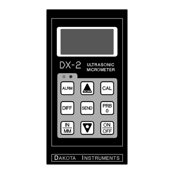
The Keypad This key is used to turn the DX-2 on and off. When the tool is turned ON, it will first perform a brief display test by illuminating all of the segments in the display. After one second, the tool will display the internal software version number. - Page 8 Dakota Ultrasonics The PRB-0 key is used to "zero" the DX-2 in much the same way that a mechanical micrometer is zeroed. If the tool is not zeroed correctly, all of the measurements that the tool makes may be in error by some fixed value.
- Page 9 Refer to page 188 for an explanation of the SCAN measurement mode. The DOWN arrow key has two functions. When the DX-2 is in the CAL mode, this key is used to decrease numeric values on the display. An auto-repeat function is built in, so that when the key is held down, numeric values will decrement at an increasing rate.
- Page 10 Dakota Ultrasonics The ALRM key has two functions. By holding down the ALRM key when powering up the DX-2, the audible beeper will be turned on or off accordingly. After the unit has been turned on, pressing the ALRM key will toggle the alarm mode to the on/off positions and allow the user to enter a nominal thickness value.
- Page 11 When this occurs, the batteries should be replaced. These eight vertical bars form the Stability Indicator. When the DX-2 is idle, only the left-most bar and the underline will be on. While the gauge is taking a measurement, six or seven of the bars should be on.
- Page 12 Dakota Ultrasonics When the IN symbol is on, the DX-2 is displaying a thickness value in inches. The maximum thickness that can be displayed is 19.999 inches. When the MM symbol is on, the DX-2 is displaying a thickness value in millimeters.
- Page 13 DX-2. The transducer must be used correctly in order for the DX-2 to produce accurate, reliable measurements. Below is a short description of the transducer, followed by instructions for its use.
-
Page 14: Making Measurements
The Stability Indicator should have six or seven bars darkened, and a number should appear in the display. If the DX-2 has been properly "zeroed" (see page 133) and set to the correct sound velocity (see page 144), the number in the display will indicate the... - Page 15 Occasionally, a small film of couplant will be drawn out between the transducer and the surface as the transducer is removed. When this happens, the DX-2 may perform a measurement through this couplant film, resulting in a measurement that is larger or smaller than it should be. This...
-
Page 16: Condition And Preparation Of Surfaces
Dakota Ultrasonics Condition and Preparation of Surfaces In any ultrasonic measurement scenario, the shape and roughness of the test surface are of paramount importance. Rough, uneven surfaces may limit the penetration of ultrasound through the material, and result in unstable, and therefore unreliable, measurements. The surface being measured should be clean, and free of any small particulate matter, rust, or scale. -
Page 17: Probe Zero
Check that the wearface of the transducer is clean and free of any debris. 3) The metal probe-disc is on the top end of the DX-2. Apply a single droplet of ultrasonic couplant to the face of this disc. - Page 18 This will ensure that the instrument is always correctly zeroed. Calibration In order for the DX-2 to make accurate measurements, it must be set to the correct sound-velocity for the material being measured. Different types of material have different inherent sound-velocities. For example, the velocity of sound through steel is about 0.233 inches-per-microsecond,...
-
Page 19: Calibration To A Known Thickness
8) Press the CAL key again. The IN/µ s (or M/s) symbols should begin flashing. The DX-2 is now displaying the sound velocity value it has calculated based on the thickness value that was entered in step 7. -
Page 20: Calibration To A Known Velocity
(0.233 IN/µs). To achieve the most accurate measurements possible, it is generally advisable to always calibrate the DX-2 to a sample piece of known thickness. Material composition (and thus, its sound-velocity) sometimes varies from lot to lot and from manufacturer to manufacturer. Calibration to a sample of known thickness will ensure that the tool is set as closely as possible to the sound velocity of the material to be measured. -
Page 21: Two Point Calibration
7 on the second calibration point. The DX-2 will now display the sound velocity value it has calculated based on the thickness values that were entered in step 7. 9) The DX-2 is now ready to perform measurements within this range. -
Page 22: Scan Mode
While the DX-2 excels at making single point measurements, it is sometimes desirable to examine a larger region, searching for the thinnest point. The DX-2 includes a feature, called Scan Mode, which allows it to do just that. In normal operation, the DX-2 performs and displays four measurements every second, which is quite adequate for single measurements. -
Page 23: Alarm Mode
DX-2 Ultrasonic Micrometer Alarm Mode The Alarm Mode feature of the DX-2 allows the user to set an audible and visual parameter when taking measurements. If the measurement falls below a nominal value, set by the user, a red light will be illuminated on the front panel of the gauge and the beeper sounded. -
Page 24: Differential Mode
DOWN arrow keys to scroll to the desired nominal alarm value. 5) Press the ALRM key once again to select the nominal value entered. 6) The DX-2 is now ready to perform measurements using the Alarm feature. Differential Mode In the Quality Control environment, it is sometimes necessary to know the difference between a nominal (target) thickness value and an actual thickness value. -
Page 25: Rs232 Serial Port
(part# N-210-0100), the DX-2 has the ability to connect to a computer, or external storage device. The following section outlines the procedure for connecting the DX-2 to a computer, and how to collect data using any standard communications program:... -
Page 26: Connecting To A Computer
Connecting To a Computer 1) Connect the accessory cable (part# N-210-0100) to the 2 pin jack located on the top of the DX-2, and the 9 pin connector to a serial port on the computer. 2) Start the communications software that will be used to collect the measurements (i.e. -
Page 27: Transducer Selection
As ultrasound travels through any material, it is partly absorbed. If the material through which the sound travels has any grain structure, the sound waves will experience scattering. Both of these effects reduce the strength of the waves, and thus, the DX-2's ability to detect the returning echo. - Page 28 Dakota Ultrasonics Higher frequency ultrasound is absorbed and scattered more than ultrasound of a lower frequency. While it may seem that using a lower frequency transducer might be better in every instance, low frequencies are less directional than high frequencies. Thus, a higher frequency transducer would be a better choice for detecting the exact location of small pits or flaws in the material being measured.
- Page 29 DX-2 Ultrasonic Micrometer transducers in order to find one that works well for a given job. Dakota Ultrasonics can provide assistance in choosing a transducer, and offers a broad selection of transducers for evaluation in specialized applications.
- Page 30 Dakota Ultrasonics blank page...
- Page 31 DX-2 Ultrasonic Micrometer APPENDIX A Product Specifications Physical Weight: 7 ounces Size: 3.25W x 6.0H x 1.35D inches (82.5W x 152.4H x 34.3D mm). Operating Temperature: -20 to 120 °F (-20 to 50 °C) Case: impact resistant ABS plastic Keypad Sealed membrane, resistant to water and petroleum products.
- Page 32 Dakota Ultrasonics blank page...
- Page 33 DX-2 Ultrasonic Micrometer APPENDIX B Application Notes • Measuring pipe and tubing When measuring a piece of pipe to determine the thickness of the pipe wall, orientation of the transducers is important. If the diameter of the pipe is larger than approximately 4 inches, measurements should be made with the transducer oriented so that the gap in the wearface is perpendicular (at right angle) to the long axis of the pipe.
- Page 34 (refer to page 14) on a sample piece of known thickness, which is at or near the temperature of the material to be measured. This will allow the DX-2 to correctly calculate the velocity of sound through the hot material.
- Page 35 DX-2 Ultrasonic Micrometer An additional important consideration when measuring laminates, is that any included air gaps or pockets will cause an early reflection of the ultrasound beam. This effect will be noticed as a sudden decrease in thickness in an otherwise regular surface. While this may impede accurate measurement of total material thickness, it does provide the user with positive indication of air gaps in the laminate.
- Page 36 Dakota Ultrasonics blank page...
- Page 37 DX-2 Ultrasonic Micrometer APPENDIX C Sound Velocities of some Common Materials M a t e r i a l s o u n d v e l o c i t y i n / u s m / s A l u m i n u m 0 .
- Page 38 Dakota Ultrasonics blank page...
-
Page 39: Warranty Information
Dakota Ultrasonics warrants transducers and accessories against such defects for a period of 90 days from receipt by the end user. If Dakota Ultrasonics receives notice of such defects during the warranty period, Dakota Ultrasonics will either, at its option, repair or replace products that prove to be defective. - Page 40 Dakota Ultrasonics blank page...
Need help?
Do you have a question about the DX-2 and is the answer not in the manual?
Questions and answers