Table of Contents
Advertisement
Quick Links
Distributed by: ABQ Industrial LP USA
Tel: +1 (281) 516-9292 / (888) 275-5772 eFax: +1 (866) 234-0451
Web: https://www.abqindustrial.net E-mail: info@abqindustrial.net
OPERATION MANUAL
Dakota NDT
F
X
7
0
S
e
r
i
e
s
F
X
7
0
S
e
r
i
e
s
Material & Coating Thickness Gauge
(Manual 1 of 2)
Distributed by: ABQ Industrial LP USA
Tel: +1 (281) 516-9292 / (888) 275-5772 eFax: +1 (866) 234-0451
Web: https://www.abqindustrial.net E-mail: info@abqindustrial.net
Advertisement
Table of Contents

Related Manuals for DAKOTA ULTRASONICS FX70 Series


Summary of Contents for DAKOTA ULTRASONICS FX70 Series
- Page 1 Distributed by: ABQ Industrial LP USA Tel: +1 (281) 516-9292 / (888) 275-5772 eFax: +1 (866) 234-0451 Web: https://www.abqindustrial.net E-mail: info@abqindustrial.net OPERATION MANUAL Dakota NDT Material & Coating Thickness Gauge (Manual 1 of 2) Distributed by: ABQ Industrial LP USA Tel: +1 (281) 516-9292 / (888) 275-5772 eFax: +1 (866) 234-0451 Web: https://www.abqindustrial.net E-mail: info@abqindustrial.net...
-
Page 3: Table Of Contents
CONTENTS CHAPTER ONE INTRODUCTION ..............1 1.1 G ......................1 ENERAL ISCLAIMER CHAPTER TWO QUICK STARTUP GUIDE ............2 2.1 FX70 O ........................2 VERVIEW 2.2 A ....................5 ROBE ECOGNITION 2.3 S ..................6 ELECTING THE RANSDUCER 2.4 P &... - Page 4 4.3 R ................. 35 ANGE OF MEASUREMENT AND ACCURACY 4.4 C ......................... 35 OUPLANT 4.5 T ........................36 EMPERATURE 4.6 M ...................... 36 EASUREMENT ODES CHAPTER FIVE SELECTING THE MEASUREMENT MODE ......39 5.1 T ......................39 HE SETUP LIBRARY 5.2 W &...
- Page 5 10.6 G (A-S ) ................114 RATICULE ACKGROUND 10.7 P ........................116 OLARITY 10.8 P ........................ 118 ULSE IDTH 10.9 P ......................119 ULSER OLTAGE 10.10 D ........................120 AMPING 10.11 GAIN SLOPE (TDG) ....................121 10.12 A ........................122 10.13 H .......................
-
Page 7: Chapter One Introduction
CHAPTER ONE INTRODUCTION The Dakota NDT model FX70 is both, an ultrasonic thickness gauge, as well as a flaw detector. Since the FX70 is basically two gauges in a single package, we split the manual into two manuals, one for each gauge type. This manual will focus only on the thickness gauge portion of the gauge. -
Page 8: Chapter Two Quick Startup Guide
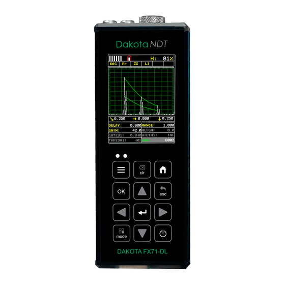
CHAPTER TWO QUICK STARTUP GUIDE Turn the FX70 on and off using the switch located on the bottom right corner of the keypad. When FX70 is initially turned on, a flash logo and blinking lights will be displayed, followed by attempting to identify the transducer (probe) currently plugged into the gauge. - Page 9 FX70 Series Ultrasonic Thickness Gauge In order to understand how to operate the FX70, it’s best to start off with an understanding of what it is we’re looking at exactly. The FX70 has a lot of great features and tools that will prove to be a huge benefit for the variety of applications you’re constantly facing on a continual basis.
- Page 10 Dakota NDT H. Digital Material Thickness Value – Smaller font size when the B-Scan display view is enabled. I. Coating Thickness Value – Displays the actual thickness of any coating adhered to a metallic material surface (PECT Mode), or a coating adhered to a non-metallic surface (CT Mode).
-
Page 11: Auto Probe Recognition
FX70 Series Ultrasonic Thickness Gauge 2.2 Auto Probe Recognition When the FX70 is initially powered up, the gauge will automatically check to see if the transducer plugged into the gauge can be recognized. The steps that follow assume the FX70 recognized the probe type:... -
Page 12: Selecting The Transducer Type
Dakota NDT 3) Press the arrow keys to toggle the coating option on/off. 4) Wipe all couplant from the transducer face and advance to the Probe Zero & Calibration section outlined below. 2.3 Selecting the Transducer Type If the FX70 does not identify a specific transducer type on initial power up, the user will be required to select a type from a predefined list of types by diameter and frequency. - Page 13 FX70 Series Ultrasonic Thickness Gauge Selecting the Transducer Type 1) Press the keys to display the factory list of transducer types (by diameter and frequency). 2) Press the arrow keys to scroll through the transducer list until the appropriate type is highlighted.
-
Page 14: Probe Zero & Calibration
Dakota NDT 3) Press the key to select the transducer type and display overwrite existing probe screen. 4) Press the key to overwrite the existing probe type with the newly selected probe type. The zero probe screen will be displayed. Proceed to the zero probe section that follows. - Page 15 FX70 Series Ultrasonic Thickness Gauge Performing an Auto Probe Zero (Off Block) Coating Probe Identified Coating Probe Not Identified 1) Be sure all couplant has been removed from the face of the transducer. 2) Press the key to perform the automatic probe zero, or key to cancel the zero operation.
- Page 16 Dakota NDT Performing a Manual Probe Zero (On Block) Note: When the zero probe option is set to manual, the probe zero disk (battery cap) located on the top of the gauge, will be used as a zero standard and the warning screen illustrated above will be displayed. 1) Press the keys to enter the main measurement screen and begin the manual zero process.
- Page 17 FX70 Series Ultrasonic Thickness Gauge Coating Probe Identified Coating Probe Not Identified 5) Press the key to display the confirmation screen. 6) If a coating transducer was identified use the arrow keys to toggle coating on/off. 7) Press the key to complete the probe zero function, or key to cancel the probe zero function.
- Page 18 Dakota NDT Using a Known Thickness Note: Be sure that the probe zero procedure has been performed prior to performing this calibration procedure. 1) Physically measure an exact sample of the material or a location directly on the material to be measured using a set of calipers or a digital micrometer. 2) Apply a drop of couplant on the transducer and place the transducer in steady contact with the sample or actual test material.
-
Page 19: Zero Coating
FX70 Series Ultrasonic Thickness Gauge 4) Press the key to display the Digits Edit Box. 5) Press the arrow keys to scroll the highlighted value. 6) Press the arrow keys to scroll the digit locations. 7) Repeat steps 5 & 6 until the known thickness value is correctly displayed. - Page 20 Dakota NDT eliminating potential errors incurred from slight differences in the manufacturing processes. The procedure is outlined below: Performing a Coating Zero 1) Press the key once to activate the measurement mode options. 2) Use the arrow keys to scroll through the sub menu items until Coating Only (CT) mode is highlighted.
-
Page 21: Coating Calibration
FX70 Series Ultrasonic Thickness Gauge 6) Use the arrow keys to scroll through the sub menu items until ZERO COATING is highlighted. 7) Press the key to display the confirmation screen. 8) Press the key to zero the coating and return to the PRB menu, or to cancel the coating zero process. - Page 22 Dakota NDT mode, or a two point calibration is CT (coating only) mode. For the purpose of this quick start section only the 1pt option PECT (pulse-echo coating) mode will be covered. Refer to the calibration section of the manual for a complete explanation on the coating calibration options.
- Page 23 FX70 Series Ultrasonic Thickness Gauge 5) Press the arrow keys to scroll the digit locations. 6) Repeat steps 4 & 5 until the velocity number is correctly displayed. 7) Press the key to set the coating velocity and return to the menu screen, or to cancel entering the coating velocity.
- Page 24 Dakota NDT couplant on a piece of metal, lay the coating sample over the couplant on the metal and proceed to step 2. 2) Apply a drop of couplant on the transducer and place the transducer in steady contact with the coating (on metal) sample or actual test material. Be sure that the reading is stable and the repeatability indicator, in the top left corner of the display, is fully lit and stable.
-
Page 25: Measure
FX70 Series Ultrasonic Thickness Gauge 8) Press the key to calculate the coating velocity and return to the menu screen, or to cancel the one point calibration. 9) Finally, press the key to return to the measurement screen and begin taking readings. - Page 26 Dakota NDT 1) Press the key once to activate the menu items tab. Press the key multiple times to tab right and the key multiple times to tab left until the DISP menu is highlighted and displaying the submenu items. 2) Use the arrow keys to scroll through the sub menu items until VIEW is highlighted.
- Page 27 FX70 Series Ultrasonic Thickness Gauge is the same as B-Depth. Therefore, these items will be grouped together for the duration of this manual, as follows: Delay (B-Start) and Range (B-Depth). Use the following steps to adjust these settings directly from the measurement screen as...
- Page 28 Dakota NDT 4) Press the key once to activate measure menu items. Press the key multiple times to move right and the key multiple times to move left, until the either the DELAY (START) or RANGE (DEPTH) cell is highlighted. 1) Press the key to display the digits edit box.
- Page 29 FX70 Series Ultrasonic Thickness Gauge Note: The DELAY (START) & WIDTH (DEPTH) can also be adjusted from the tabbed menu item DISP. However, using the hot menu keys is the easiest method. RF View Rectified (RECT) View DIGITS View BSCAN View In the upper left corner of each of the display photos above, is the repeatability indicator.
-
Page 30: Chapter Three Keyboard, Menu, & Connector Reference
CHAPTER THREE KEYBOARD, MENU, & CONNECTOR REFERENCE 3.1 Menu Key (Operation & Sub Menus) The Menu key activates the primary menu structure containing 8 menu tab groups. These tab groups then contain sub menu items, or functions. The sub menu items have been organized in tab groups according to how closely they are related to the individual tab group names. - Page 31 FX70 Series Ultrasonic Thickness Gauge Activating and Getting Around in the Menu Items 1) Press the key once to activate the menu items tab. Press the key multiple times to tab right, and the key multiple times to tab left until the desired tab group is highlighted and displaying the submenu items (B).
-
Page 32: Probe - Menu
Dakota NDT 3.2 Probe – Menu ZERO PROBE: The FX70 is zeroed in much the same way that a mechanical micrometer is zeroed. If the FX70 is not zeroed correctly, all of the measurements made using the FX70 may be in error by some fixed value. The FX70 is equipped with an optional automatic or manual zero feature. -
Page 33: Disp (Display) - Menu
FX70 Series Ultrasonic Thickness Gauge COATING 2PT: Performs a two-point coating calibration. This option allows the user to automatically calculate the velocity by entering a second known coating sample thickness. Refer to page 102 for further info. COATING VEL: Function to calibrate the FX70 to a specific coating material type by entering a coating velocity. -
Page 34: Tune - Menu
Dakota NDT GRATICULE: Selectable graphics option for the A-Scan background (grid/segments) used as references to depth/thickness versus amplitude. The options are: Point, Line, Dots, Mix. Offers the user a graphics preference on how they prefer to view the A-Scan waveform area. Refer to page 114 for further info. 3.5 TUNE –... -
Page 35: Gt1 - Menu
FX70 Series Ultrasonic Thickness Gauge The higher the number the better the dynamic gain range, and visa versa. Refer to page 72 for further info. GAIN SLOPE (TIME DEPENDENT GAIN): Similar to ‘time corrected gain’ but a linear gain ramp that increases the output of the FX70 at a constant rate over time (dB per microsecond). -
Page 36: Setup - Menu
Dakota NDT GATE3 WIDTH: This feature allows the user to set the overall width of the gate, in terms of distance, from the starting value of HoldOff3. Refer to page 81 for further info. HOLDOFF 3: Provides the user with the ability to delay the starting point of Gate3, a specific distance from the first detection point found inside of the boundaries of the Gate 2 settings. -
Page 37: Util (Utilities) - Menu
FX70 Series Ultrasonic Thickness Gauge columns depending on the user’s application reporting requirements. Refer to page 135 for further info. EDIT: Gives the user the ability to change parameters of grid or sequential file previously saved. Note: Pre-defined coordinates cannot be changed once they have been created. -
Page 38: Xfer (Transfer) - Menu
Dakota NDT KEY CLICK: Give the user the ability to set the level of the key press beeper, OFF, QUIET, or LOUD. Refer to page 128 for further info. SET DATE: Gives the user the ability to set the internal date and time stamp in the FX70. -
Page 39: Esc Key
FX70 Series Ultrasonic Thickness Gauge 3.16 ESC Key The ESC key is used in conjunction with the , and EDIT functions as a back or escape function. If the FX70 is displaying a grid or sequential log, the key toggles the display options: Digits, RF, RECT, and B-Scan views. -
Page 40: Top & Bottom End Caps
3.21 Top & Bottom End Caps The top & bottom end panels are where all connections are made to the FX70. The diagram above shows the layout and description of the connectors: Transducer Connectors Refer to Diagram: The transducer connectors and battery cover/probe zero disk are located on the FX70’s top end cap. -
Page 41: Chapter Four Principals Of Ultrasonic Measurement
CHAPTER FOUR PRINCIPALS OF ULTRASONIC MEASUREMENT 4.1 Time versus thickness relationship Ultrasonic thickness measurements depend on measuring the length of time it takes for sound to travel through the material being tested. The ratio of the thickness versus the time is known as the sound velocity. In order to make accurate measurements, a sound velocity must be determined and entered into the instrument. -
Page 42: Temperature
Dakota NDT 4.5 Temperature Temperature has an effect on sound velocity. The higher the temperature, the slower sound travels in a material. High temperatures can also damage transducers and present a problem for various liquid couplants. Since the sound velocity varies with temperature it is important to calibrate at the same temperature as the material being measured. - Page 43 FX70 Series Ultrasonic Thickness Gauge detecting small defects. Also, the surface of the test material does not have to be as flat in order to obtain good measurements. Dual element transducers are normally used in pulse-echo mode for finding defects, and in echo-echo mode for through coating measurements.
- Page 44 Dakota NDT jump has not occurred, providing an additional level of confidence to the measurement. The disadvantage is that 3 reflections are needed which requires the use of gates with controllable thresholds to adjust for sensitivity over a given measurement range. Dual Element Transducer in Echo to Echo mode Pulse Echo Coating Mode –...
-
Page 45: Chapter Five Selecting The Measurement Mode
CHAPTER FIVE SELECTING THE MEASUREMENT MODE 5.1 The setup library The FX70 contains 64 user configurable preset locations to store custom setups for easy recall. These setups can be optimized for the user’s specific application needs and can also be stored on a PC and transferred bi-directionally using Dakota’s PC interface software included with the instrument. - Page 46 Dakota NDT the coating or paint is not completely removed. By using echo-echo mode, the user is able to successfully measure through both, the coating and steel, and completely eliminate the thickness of the paint or coating. Therefore, the steel can be measured without having to remove the coating prior to measuring.
-
Page 47: Factory Setup Chart
FX70 Series Ultrasonic Thickness Gauge 5.3 Factory Setup Chart Name Comment 1 Gn/AGC Velocity Enter Custom Name … … … … … … …... -
Page 48: Chapter Six Making Measurements
CHAPTER SIX MAKING MEASUREMENTS The steps involved in making measurements are detailed in this section. The following sections outline how to setup and prepare your FX70 for field use. An automatic or manual zero must always be performed. The auto zero is an off block electronic zero that does not require a zero reference block. - Page 49 FX70 Series Ultrasonic Thickness Gauge In this first example the transducer was automatically identified: Probe Automatically Recognized 1) Press the key once to use the identified probe, or to display a list of optional transducers. Note: if the FX70 recognizes a specific transducer, the user should always select to use the identified probe.
- Page 50 Dakota NDT 3) Press the arrow keys to toggle the coating option on/off. 4) Wipe all couplant from the transducer face and proceed to the Probe Zero section that follows. In this second example the transducer was not identified and will force the user to select the transducer type from a predefined list of transducers: Selecting the Transducer Type 5) Press the...
-
Page 51: Probe Zero
FX70 Series Ultrasonic Thickness Gauge 6) Press the arrow keys to scroll through the transducer list until the appropriate type is highlighted. 7) Press the key to select the transducer type and display overwrite existing probe screen. 8) Press the key to overwrite the existing probe type with the newly selected probe type. - Page 52 Dakota NDT intervals during operation if it hasn’t been done. If the FX70 is not zeroed correctly, all the measurements taken may be in error by some fixed value. When the FX70 is using the auto zero (electronic zero), the FX70 can be in any measurement mode. However, when the manual zero is being used, the FX70 must be in pulse-echo mode in order to perform the zero.
- Page 53 FX70 Series Ultrasonic Thickness Gauge Coating Probe Identified Coating Probe Not Identified 3) The screens illustrated above will be briefly displayed followed by the main measurement screen. The FX70 is ready to be calibrated.
- Page 54 Dakota NDT Performing a Manual Probe Zero (On Block) Note: When the zero probe option is set to manual, the probe zero disk (battery cap) located on the top of the gauge will be used as a zero standard and the warning screen illustrated above will be displayed. 1) Press the keys to enter the main measurement screen and begin the manual zero process.
-
Page 55: Material Calibration
FX70 Series Ultrasonic Thickness Gauge Coating Probe Identified Coating Probe Not Identified 5) Press the key to display the confirmation screen. 6) If a coating transducer was identified use the arrow keys to toggle coating on/off. 7) Press the key to complete the probe zero function, or key to cancel the probe zero function. - Page 56 Dakota NDT all of the measurements the gauge makes will be erroneous by some fixed percentage. The One Point calibration is the simplest and most commonly used calibration method - optimizing linearity over large ranges. The Two Point calibration allows for greater accuracy over small ranges by calculating the probe zero and velocity.
- Page 57 FX70 Series Ultrasonic Thickness Gauge 3) Press the key to display the Digits Edit Box. 4) Press the arrow keys to scroll the highlighted value. 5) Press the arrow keys to scroll the digit locations. 6) Repeat steps 4 & 5 until the velocity number is correctly displayed.
- Page 58 Dakota NDT Known Thickness Sometimes the sound velocity of a material is unknown. In this case a sample with one or two known thicknesses can be used to determine the sound velocity. As previously discussed, the FX70 has a one or two point calibration option. The one point calibration option is most suited for linearity over large ranges, as noted above.
- Page 59 FX70 Series Ultrasonic Thickness Gauge multiple times to tab left until the CAL menu is highlighted and displaying the submenu items. 3) Use the arrow keys to scroll through the sub menu items until MATL 1PT is highlighted. 4) Press the key to display the Digits Edit Box.
- Page 60 Dakota NDT At some point there may become a requirement for improved accuracy over a smaller measurement range. In this case, a two point calibration would be most suited for the job. For example, if the measurement range was .080” (2.03mm) to .250” (6.35mm), the user would perform a one point calibration on a known thickness sample close to .250”...
- Page 61 FX70 Series Ultrasonic Thickness Gauge 4) Press the key to display the Digits Edit Box. 5) Press the arrow keys to scroll the highlighted value. 6) Press the arrow keys to scroll the digit locations. 7) Repeat steps 5 & 6 until the known thickness value is correctly displayed.
- Page 62 Dakota NDT being tested. Use these values only if a close approximation is acceptable. Follow the steps below to select a basic material type: Selecting a Basic Material Type 1) Press the key once to activate the menu items tab. Press the key multiple times to tab right and the key multiple times to tab left until the CAL menu is highlighted and displaying the submenu items.
- Page 63 FX70 Series Ultrasonic Thickness Gauge 4) Press the arrow keys to scroll through the material list until the appropriate material is highlighted. 5) Press the key to overwrite the material type and display the menu items with the new material type selected.
-
Page 64: Chapter Seven Using The Display Options
CHAPTER SEVEN USING THE DISPLAY OPTIONS A key feature of the FX70 is the ability to toggle between four different display options; Digits, RF, RECT and B-Scan. All views provide a digital readout of base material and coating thickness measurements, while also displaying the alarm tolerances, if active. -
Page 65: Display Views
FX70 Series Ultrasonic Thickness Gauge 7.1 Display Views DIGITS VIEW DIGITS The Digits view is a basic digital thickness gauge look and feel. The larger digits make it much easier for the operator to monitor the thickness readings. The Scan... - Page 66 Dakota NDT F. Scan Bar – Another view of material thickness in a deflection style horizontal bar. This is another visual tool that would enable the user the ability to see thickness changes during high speed scans from flaws and pits. G.
- Page 67 FX70 Series Ultrasonic Thickness Gauge A. Repeatability/Stability Indicator – This indicator should be commonly used in conjunction with the digital thickness values displayed. When all the vertical bars are fully illuminated and the last digit on the digital thickness value is stable, the FX70 is reliably measuring the same value 3 to 200 times per second, depending on which measurement mode and features are enabled.
- Page 68 Dakota NDT RF A-Scan View Radio Frequency (RF) A-Scan The RF mode shows the waveform in a similar fashion to an oscilloscope. It shows both the positive and the negative peaks. The peak (either positive or negative) selected for measurement is shown in upper portion of the display. It’s important to note that a measurement must fall inside the displays viewable range in order to see the waveform.
- Page 69 FX70 Series Ultrasonic Thickness Gauge known as the threshold, and controls the sensitivity of the reflections that trigger a detection from the opposite surface of the material. F. Measurement Scale – Represents thickness values over a defined measurement range, and labeled at the calibrated hash marks on the display (X) axis.
- Page 70 Dakota NDT RECT A-Scan View Rectified (RECT) A-Scan The RF mode shows the waveform in a similar fashion to an oscilloscope. It shows both the positive and the negative peaks. The peak (either positive or negative) selected for measurement is shown in upper portion of the display. It’s important to note that a measurement must fall inside the displays viewable range in order to see the waveform.
- Page 71 FX70 Series Ultrasonic Thickness Gauge known as the threshold, and controls the sensitivity of the reflections that trigger a detection from the opposite surface of the material. F. Measurement Scale – Represents thickness values over a defined measurement range, and labeled at the calibrated hash marks on the display (X) axis.
-
Page 72: Changing Display Options
Dakota NDT 7.2 Changing Display Options The following procedure outlines how to select or toggle display options: Changing Display Options Color VGA 1) Press the key once to activate the menu items tab. Press the key multiple times to tab right, and the key multiple times to tab left, until the DISP menu is highlighted and displaying the submenu items. -
Page 73: Adjusting The Display
FX70 Series Ultrasonic Thickness Gauge 7.3 Adjusting the display This section will cover the procedures for adjusting the viewable range, or area, of the display, in terms of thickness. A basic overview of this section would be as follows: Suppose we had a 50” widescreen television set. Assume that you’re watching the television for rest of this explanation. - Page 74 Dakota NDT Adjusting Delay (B-Start) using the Hot Menus 1) Press the key once to activate measure menu items. Press the key multiple times to move right and the key multiple times to move left, until the DELAY cell is highlighted. 2) Press the , and arrow keys to scroll the highlighted...
- Page 75 FX70 Series Ultrasonic Thickness Gauge 6) Repeat steps 4 & 5 until the DELAY value is correctly displayed. 7) Press the key to return to the measurement screen, or to cancel entering the DELAY. 8) Finally, press the key to return to the measurement screen and begin taking readings.
- Page 76 Dakota NDT 2) Press the , and arrow keys to scroll the highlighted value. 3) Alternatively, press the key to display the Digits Edit Box. 4) Press the arrow keys to scroll the highlighted value. 5) Press the arrow keys to scroll the digit locations. 6) Repeat steps 4 &...
- Page 77 Adjusting the B-Scan Speed The FX70 has the capability to adjust the the scrolling speed of the time based B- Scan displayed in the gauge. The procedures to adjust the speed are outlined below: Adjusting the B-Scan Speed 1) Press the key once to activate the menu items tab.
-
Page 78: Gain
Dakota NDT 7) Repeat steps 5 & 6 until the SPEED is correctly displayed. 8) Press the key to set the speed and return to the DISP menu., followed by pressing the key to begin the B-Scan process. 9) Finally, press the key to return to the measurement screen and begin the scanning process. - Page 79 FX70 Series Ultrasonic Thickness Gauge might be the need to increase overall sensitivity for locating fine pits or flaws. In any case, the adjustable gain feature offers the user some additional options to resolve and overcome application issues. Note: When the echo-echo thru-paint, or echo-echo-verify measurement modes are selected, the manual gain feature is disabled and grayed out in the menu items.
- Page 80 Dakota NDT 3) Alternatively, press the key to display the Digits Edit Box. 4) Press the arrow keys to scroll the highlighted value. 5) Press the arrow keys to scroll the digit locations. 6) Repeat steps 4 & 5 until the GAIN value is correctly displayed. 7) Press the key to return to the measurement screen, or to cancel...
- Page 81 FX70 Series Ultrasonic Thickness Gauge 1) Press the key once to activate the menu items tab. Press the key multiple times to tab right, and the key multiple times to tab left, until the TUNE menu is highlighted and displaying the submenu items.
- Page 82 Dakota NDT 9) Finally, press the key to return to the measurement screen and begin taking readings.
-
Page 83: Threshold
FX70 Series Ultrasonic Thickness Gauge 7.5 Threshold The Threshold is the level (sensitivity) of the signal amplitude required to trigger the thickness reading. This level can be used in conjunction with the gain. Example: suppose the user can visually see a potential flaw on the display, but the FX70 is not detecting on the flaw because the Gain is too low, or the Threshold to high. - Page 84 Dakota NDT 2) If the correct THRESHOLD is displayed, press the , and arrow keys to scroll the highlighted value. 3) Alternatively, if the correct Threshold is not being displayed, press the key to display the List Box. 4) Use the arrow keys to scroll through the List Box items until the correct THRESHOLD is highlighted.
- Page 85 FX70 Series Ultrasonic Thickness Gauge 1) Press the key once to activate the menu items tab. Press the key multiple times to tab right, and the key multiple times to tab left, until the GT1 menu is highlighted and displaying the submenu items.
- Page 86 Dakota NDT 10) Finally, press the key to return to the measurement screen and begin taking readings.
-
Page 87: Understanding The Features Of The Gate
FX70 Series Ultrasonic Thickness Gauge 7.6 Understanding the features of the Gate Important: It is recommended to spend some time in this section. The sections that follow are procedures for using the features associated with the Gates, in some way. - Page 88 Dakota NDT pulse, or in the material, the gate can be moved to the right of the noise and block the unwanted noise. Gates 2 and 3 will automatically start from the end of gate 1, or from a detection found inside of the boundaries of gate 1. Therefore, we use a hold- off delay as a start feature for gates 2 and 3.
- Page 89 FX70 Series Ultrasonic Thickness Gauge Activating the gates: Automatically: The gates are automatically activated, when a measurement mode is selected. Gate1 is active in all measurement modes. These modes have been internally setup at the Dakota factory. Therefore, if the user selects the Thru Coat (E-E) option, an internal setup will be loaded, and 2 gates will automatically be activated.
-
Page 90: Gates
Dakota NDT 7.7 Gates The FX70 is equipped with 3 gates, as explained in the previous section. One gate is active at all times in every measurement mode, with the exception of coating mode. These gates are full featured and completely adjustable. They can be fine tuned by the user to accommodate a variety of application scenarios. - Page 91 FX70 Series Ultrasonic Thickness Gauge Example of Surface or Transducer Noise Noise Blocked The diagrams above illustrate a typical surface noise condition. Refer to the Noise diagram: (A) refers to the noise in front of the actual back wall signal (C). Notice the start position of the gate.
- Page 92 Dakota NDT Note: This is a combined procedure that works the same for any of the features associated with the gates, regardless of which feature and gate number that is being adjusted. Therefore (Ж) = Gate1, Hold-Off, and Width respectively. Finally, the illustrations may not be applicable to the exact feature being adjusted, but the concepts relevant.
- Page 93 FX70 Series Ultrasonic Thickness Gauge 5) Press the key to return to the measure screen and Hot Menu items. 6) Press the , and arrow keys to scroll the highlighted value. 7) Repeat steps 3-6 until all the (Ж) values are correctly adjusted.
- Page 94 Dakota NDT 4) Alternatively, press the key to display the Digits Edit Box. 5) Press the arrow keys to scroll the highlighted value. 6) Press the arrow keys to scroll the digit locations. 7) Repeat steps 5 & 6 until the (Ж) number is correctly displayed. 8) Press the key to set the (Ж) and return to the menu screen, or to cancel entering the (Ж).
-
Page 95: Chapter Eight Thru Paint Measurement Technique
CHAPTER EIGHT THRU PAINT MEASUREMENT TECHNIQUE 8.1 Introduction to Thru Paint Measurement The principle behind thru paint measurement is by measuring the time between two backwall echoes returning from the test material. Since both of these backwall echoes travel the same path through the paint or coating, the thickness of the coating is subtracted out of the measurement so that only the actual material thickness can be measured. - Page 96 Dakota NDT mode button on the keypad. The FX70 has been programmed to identify the modes available to a specific transducer. When configuring the FX70 for specific thru paint applications, all of the scope parameters will potentially be needed. The delay, range, gain (AGC), thresholds, gates, and hold-offs will be subject to change.
- Page 97 FX70 Series Ultrasonic Thickness Gauge the first back wall echo no longer interferes with the true detection (D), shown in the correct diagram. The adjustment considerations in the example above will typically be used for all thru paint applications respectively. In some applications the hold-off may be sufficient, while a gain (AGC) or thresholds adjustment will solve the problem.
-
Page 98: Chapter Nine Pulse-Echo Coating & Coating Techniques
CHAPTER NINE PULSE-ECHO COATING & COATING TECHNIQUES 9.1 Introduction to Pulse-Echo Coating Measurement (PECT) In the previous sections we’ve discussed the need for detecting pits and flaws (pulse- echo) in materials, along with the requirement to measure through and eliminate errors caused by coated materials (echo-echo). - Page 99 FX70 Series Ultrasonic Thickness Gauge 3) From the tabbed menus under TUNE, MEASURE MODE. The steps that follow will demonstrate all three methods in the order listed above: Probe Automatically Recognized (PECT only) 1) Press the key once to use the identified probe, or to display a list of optional transducers.
- Page 100 Dakota NDT 3) Press the arrow keys to toggle the coating option on/off. Multi Mode Key Pressed (PECT & CT) Applied to Metals Not Applied to Metals 1) Press the key located on bottom left of the keypad to display the URE MODE options menu.
- Page 101 FX70 Series Ultrasonic Thickness Gauge 3) Press the key to enable the coating option, or to cancel changing the measure mode, and return to the main measurement screen. Measure Mode (Tabbed Menus) – (PECT & CT) Applied to Metals Not Applied to Metals 1) Press the key once to activate the menu items tab.
-
Page 102: Zero Coating
Dakota NDT 9.3 Zero Coating In order to account for very slight electronic differences in transducers of the same type, frequency, and diameter, the FX70 has been equipped with a “zero coating” feature. This enables the FX70 to obtain very accurate readings on coatings, eliminating potential errors incurred from slight differences in the manufacturing processes. - Page 103 FX70 Series Ultrasonic Thickness Gauge 5) Press the key once to activate the menu items tab. Press the key multiple times to tab right and the key multiple times to tab left until the PRB menu is highlighted and displaying the submenu items.
-
Page 104: Coating Calibration (Pect)
Dakota NDT 9.4 Coating Calibration (PECT) Known Velocity If the coating velocity is known, the user may wish to simply enter the velocity number into the FX70, rather than have the FX70 calculate the velocity value using a known thickness on a coating sample(s). The steps for entering the velocity are outlined below: Using a Known Material Velocity 1) Press the... - Page 105 FX70 Series Ultrasonic Thickness Gauge 3) Press the key to display the Digits Edit Box. 4) Press the arrow keys to scroll the highlighted value. 5) Press the arrow keys to scroll the digit locations. 6) Repeat steps 4 & 5 until the velocity number is correctly displayed.
- Page 106 Dakota NDT Known Thickness Sometimes the sound velocity of a coating material is unknown. In this case a sample with a known thickness can be used to determine the sound velocity of the coating. As previously discussed, the FX70 offers a one point calibration option for coating in PECT measurement mode.
- Page 107 FX70 Series Ultrasonic Thickness Gauge actual test material. Be sure that the reading is stable and the repeatability indicator, in the top left corner of the display, is fully lit and stable. Press the key once to activate the menu items tab. Press the...
-
Page 108: Introduction To Coating Measurement (Ct)
Dakota NDT Note: CHECK YOUR CALIBRATION! Place the transducer back on the calibration point. The coating thickness reading should now match the known thickness. If the thickness is not correct, repeat the steps above. 9.5 Introduction to Coating Measurement (CT) In the previous sections we’ve discussed how to setup and use the coating feature for use in conjunction with material thickness for flaw and pit detection. - Page 109 FX70 Series Ultrasonic Thickness Gauge One Point Calibration Note: Use the maximum coating sample for the one point calibration first. 1) Physically measure the thicker of the two samples of coating, as close as possible to the maximum expected coating measurement range, using a set of calipers or a digital micrometer.
- Page 110 Dakota NDT 3) Use the arrow keys to scroll through the sub menu items until COATING 1PT is highlighted. 4) Press the key to display the Digits Edit Box. 5) Press the arrow keys to scroll the highlighted value. 6) Press the arrow keys to scroll the digit locations.
- Page 111 FX70 Series Ultrasonic Thickness Gauge Two Point Calibration Note: Use the minimum coating sample for the two point calibration. 1) Physically measure the thinner of the two samples of the coating, as close as possible to the minimum expected coating measurement range, using a set of calipers or a digital micrometer.
- Page 112 Dakota NDT 3) Use the arrow keys to scroll through the sub menu items until COATING 2PT is highlighted. 4) Press the key to display the Digits Edit Box. 5) Press the arrow keys to scroll the highlighted value. 6) Press the arrow keys to scroll the digit locations.
-
Page 113: Chapter Ten Additional Features Of The Fx70
CHAPTER TEN ADDITIONAL FEATURES OF THE FX70 10.1 Brightness The FX70 is equipped with a brightness feature to adjust the display visibility and optimize battery life. It has an arbitrary scale with a values from 1-20, with 20 representing the brightest setting. The procedures for adjusting the brightness are outlined below: Adjusting Brightness 1) Press the... -
Page 114: Colors
Dakota NDT 4) Alternatively, press the key to display the Digits Edit Box. 5) Press the arrow keys to scroll the highlighted value. 6) Press the arrow keys to scroll the digit locations. 7) Repeat steps 5 & 6 until the brightness number is correctly displayed. 8) Press the key to set the brightness and return to the menu screen, or to cancel entering the brightness. - Page 115 FX70 Series Ultrasonic Thickness Gauge 1) Press the key once to activate the menu items tab. Press the key multiple times to tab right and the key multiple times to tab left until the DISP menu is highlighted and displaying the submenu items.
-
Page 116: Landscape (A-Scan)
Dakota NDT 6) Finally, press the key to return to the measurement screen and begin taking readings. 10.3 LANDSCAPE (A-Scan) The FX70 is a very portable and compact gauge with a 2.7” AMOLED display that is used in a portrait mode as standard. In order to maximize the viewable A-Scan area of the display, the orientation of the display can be rotated to a landscape view for either right or left hand use. -
Page 117: Dim
FX70 Series Ultrasonic Thickness Gauge 4) Press the key to return to the measurement screen in standard portrait view. 5) Press the key to rotate the screen to LANDSCAPE view. Note: Portrait and Landscape modes are quickly toggled by using the keys. -
Page 118: Graphics Options (Look & Feel)
Dakota NDT 6) Press the key once to activate the menu items tab. Press the key multiple times to tab right and the key multiple times to tab left until the DISP menu is highlighted and displaying the submenu items. 7) Use the arrow keys to scroll through the sub menu items until DIM is highlighted. - Page 119 FX70 Series Ultrasonic Thickness Gauge Filled – Draws a filled version of the waveform. Detect Mark: The detect mark is another look and feel option for displaying the detection indicator.
-
Page 120: Graticule (A-Scan Background)
Dakota NDT 10.6 Graticule (A-Scan Background) The graticule markers in the background of the A-Scan waveform area provide measurement references for depth/thickness versus amplitude. There are multiple options for the user to select an A-Scan background grid/segments to satisfy their graphics preference or ‘look and feel’. - Page 121 FX70 Series Ultrasonic Thickness Gauge Points Line Dots Selecting Graticule Option 1) Press the key once to activate the menu items tab. Press the key multiple times to tab right and the key multiple times to tab left until the DISP menu is highlighted and displaying the submenu items.
-
Page 122: Polarity
Dakota NDT 2) Use the arrow keys to scroll through the sub menu items until GRATICULE is highlighted. 3) Use the arrow keys to scroll the GRATICULE options. 4) Once the desired “look & feel” is displayed, press the key to return to the measurement screen. - Page 123 FX70 Series Ultrasonic Thickness Gauge first cycle (B) and peak jump to the second cycle (F). The detect (A), would move to (F), resulting in incorrect measurements. If the user were to select the positive phase in the diagram above, the detect would measure at (H).
-
Page 124: Pulse Width
Dakota NDT 4) Press the key to return to the measurement screen and begin taking readings. Important: Be sure to do a Probe Zero after changing the polarity! 10.8 Pulse Width The FX70 has an adjustable pulse width option. Pulse width, refers to the duration of time the pulser is left on. -
Page 125: Pulser Voltage
FX70 Series Ultrasonic Thickness Gauge 4) Once the Pulse is displayed, press the key to return to the measurement screen. 10.9 Pulser Voltage The FX70 has a 200 volt square wave pulser that can be adjusted for specific applications and transducers. The Pulser Volt feature offers a 50 volt cut/boost option to the user. -
Page 126: Damping
Dakota NDT 4) Once the desired Pulser Voltage is displayed, press the key to return to the measurement screen. 10.10 Damping The FX70 has a built-in damping feature to control the impedance input of the receiver. This enables the user the ability to match and optimize the transducer for better signal quality at various frequencies. -
Page 127: Gain Slope (Tdg)
FX70 Series Ultrasonic Thickness Gauge 4) Finally, press the key to return to the measurement screen and begin taking readings. 10.11 GAIN SLOPE (TDG) The FX70 has a gain slope feature that is similar to a basic linear time corrected gain function, or “time dependent gain”... -
Page 128: Auto Find
Dakota NDT 3) Use the arrow keys to scroll through the GAIN SLOPE values until the correct value is displayed to the right of the GAIN SLOPE menu item. 4) Finally, press the key to return to the measurement screen and begin taking readings. -
Page 129: High Speed Scan
FX70 Series Ultrasonic Thickness Gauge 1) Press the key once to activate the menu items tab. Press the key multiple times to tab right, and the key multiple times to tab left, until the UTIL menu is highlighted and displaying the submenu items. -
Page 130: Alarm Mode
Dakota NDT 1) Press the key once to activate the menu items tab. Press the key multiple times to tab right and the key multiple times to tab left until the UTIL menu is highlighted and displaying the submenu items. 2) Use the arrow keys to scroll through the sub menu items until SCAN MODE is highlighted. - Page 131 FX70 Series Ultrasonic Thickness Gauge 1) Press the key once to activate the menu items tab. Press the key multiple times to tab right, and the key multiple times to tab left, until the UTIL menu is highlighted and displaying the submenu items.
-
Page 132: Differential Mode
Dakota NDT 1) Assuming the ALARM is ON, use the arrow keys to scroll through the sub menu items until ALARM LOW is highlighted. 2) Press the arrow keys to scroll the value. When the correct alarm value is being displayed, proceed to step 7. 3) Alternatively, press the key to display the Digits Edit Box. - Page 133 FX70 Series Ultrasonic Thickness Gauge Toggle Differential (on/off) 1) Press the key once to activate the menu items tab. Press the key multiple times to tab right, and the key multiple times to tab left, until the UTIL menu is highlighted and displaying the submenu items.
-
Page 134: Key Click
Dakota NDT 1) Assuming DIFFERENTIAL has been enabled and a value is being displayed to the right of the DIFFERENTIAL label, press the key to display the Digits Edit Box. 2) Press the arrow keys to scroll the highlighted value. 3) Press the arrow keys to scroll the digit locations. -
Page 135: Set Date & Time
FX70 Series Ultrasonic Thickness Gauge 1) Press the key once to activate the menu items tab. Press the key multiple times to tab right and the key multiple times to tab left until the UTIL menu is highlighted and displaying the submenu items. - Page 136 Dakota NDT 1) Press the key once to activate the menu items tab. Press the key multiple times to tab right and the key multiple times to tab left until the UTIL menu is highlighted and displaying the submenu items. 2) Use the arrow keys to scroll through the sub menu items until SET DATE is highlighted.
-
Page 137: Show Date & Time
FX70 Series Ultrasonic Thickness Gauge 7) Press the key to set the Time & Date and return to the menu screen, to cancel entering the Time & Date. 8) Finally, press the key to return to the measurement screen and begin taking readings. -
Page 138: Freeze & Capture
Dakota NDT 4) Finally, press the key to return to the measurement screen and begin taking readings. 10.19 Freeze & Capture The FX70 freeze feature enables a user to immediately freeze what’s currently being displayed on the screen for further review or analysis. The freeze feature used in conjunction with the capture feature enables a user to save the entire screen shot directly to a .tif (tagged image) file format that can be opened using any graphics viewer. - Page 139 FX70 Series Ultrasonic Thickness Gauge 3) Press the key to display the alpha numeric edit box to name and save the screen shot. 4) Press the key to return to the measurement screen.
-
Page 140: Chapter Eleven Data Storage - Setup, Edit, & View Files
CHAPTER ELEVEN DATA STORAGE – SETUP, EDIT, & VIEW FILES 11.1 Introduction to Grid and Sequential file formats The FX70 is equipped with two data file format options, GRID LOG and SEQ LOG. The GRID file format is very similar to a spreadsheet format found in popular software programs like Excel. -
Page 141: Creating A New Grid Or Sequential Log (File)
FX70 Series Ultrasonic Thickness Gauge Grid File Formats Sequential Log Formats Important Note: For the duration of this chapter, all references to GRIDS and SEQ LOGS should be considered synonymous with references to FILES. 11.2 Creating a new Grid or Sequential Log (File) Important Note: This entire section is a step by step guide to successfully create a grid or sequential log. - Page 142 Dakota NDT Grid/Seq Log Name : Can contain a combination of up to 20 numeric, alpha, or special characters listed in the first section of this chapter. Grid Log Sequential Log 1) Press the key once to activate the menu items tab. Press the key multiple times to tab right, and the key multiple times to tab left, until the DATA menu is highlighted and displaying the submenu items.
- Page 143 FX70 Series Ultrasonic Thickness Gauge Grid Log Sequential Log 4) Press the key to display the new Grid or Seq Edit Box. 5) Use the arrow keys to scroll through the new Grid or Seq List Items until NAME is highlighted.
- Page 144 Dakota NDT Creating a Note Grid/Seq Log Note: Can contain a combination of up to 20 numeric, alpha, or special characters listed in the first section of this chapter. Grid Log Sequential Log 1) Assuming the Grid or Seq List Items are displayed, use the arrow keys to scroll through the new Grid or Seq List Items until NOTE is highlighted.
- Page 145 FX70 Series Ultrasonic Thickness Gauge 3) Use the , & arrow keys to highlight the appropriate alpha characters. 4) Press the key to select a character and advance to the next field of the Grid or Seq Note. 5) Use the key to backspace if necessary.
- Page 146 Dakota NDT Once a start and end ID are entered into the FX70 and the log created, the FX70 will automatically generate all the identifiers within that range. Setting the Top Left(Grid) or Start ID(Seq) Grid Log Sequential Log 1) Use the arrow keys to scroll through the new Grid or Seq List Items until TOP or START ID is highlighted.
- Page 147 FX70 Series Ultrasonic Thickness Gauge SEQ LOG: Use the arrow keys to highlight the appropriate alpha characters. Press the key to select a character and advance to the next character field, in conjunction with using the key to backspace if necessary.
- Page 148 Dakota NDT Grid Log Sequential Log 3) GRID LOG: Use the arrow keys to scroll the Columns, and arrow keys to scroll the Rows. SEQ LOG: Use the arrow keys to highlight the appropriate alpha characters. Press the key to select a character and advance to the next character field, in conjunction with using the key to backspace if necessary.
- Page 149 FX70 Series Ultrasonic Thickness Gauge...
- Page 150 Dakota NDT Selecting the Auto Increment Direction The Auto Increment feature gives the user the ability to specify which direction to advance the cursor after storing a reading. Grid Log Sequential Log 5) Use the arrow keys to scroll through the new Grid or Seq List Items until INCR.
- Page 151 FX70 Series Ultrasonic Thickness Gauge Saving Graphics The FX70 provides the user with the ability to save a snapshot of the display screen and all the current settings of the FX70 with every reading, or just save the reading only. Saving the graphics might be advantageous to the user when the A/B-Scan views will be used to graphically save a picture of the scanned areas for reporting purposes.
- Page 152 Dakota NDT Saving a Grid Once all the parameters are set, the user has the option of saving or canceling the new grid. Grid Log Sequential Log 4) Use the arrow keys to scroll through the new Grid or Seq List Items until CREATE GRID or LOG? is highlighted.
-
Page 153: Storing A Reading
FX70 Series Ultrasonic Thickness Gauge 6) Press the key to save the New Grid or Seq Log, or the key to cancel the New Grid or Seq Log setup and return to the DATA menu. 7) Press the key to return to the measurement screen and begin storing readings. - Page 154 Dakota NDT Key Feature: When the FX70 is displaying a “grid log”, pressing the key multiple times, will toggle through the display options: Digits, RF, RECT, and B-SCAN views. Grid Log Sequential Log 1) Press the , and arrow keys to scroll the target cell cursor to the desired storage location.
-
Page 155: Viewing Stored Readings
FX70 Series Ultrasonic Thickness Gauge 11.4 Viewing stored readings It is sometimes necessary to go back and view the stored readings and B-Scans using the FX70 without a PC. The following procedures outline this process: Viewing Stored Readings & A/B Scans... -
Page 156: Deleting Grids (Files)
Dakota NDT a different cell, the display will be updated with the display view saved with the reading. Readings stored in memory are indicated by displaying a MEM in the top left corner of the measurement screen. 4) The user may opt to clear a specific reading and save a new one at any time. - Page 157 FX70 Series Ultrasonic Thickness Gauge 2) Use the arrow keys to scroll through the sub menu items until DELETE ONE FILE is highlighted. 3) Press the key to display the File List Box. 4) Use the arrow keys to scroll through the stored Files until the target File to delete is highlighted.
- Page 158 Dakota NDT 2) Use the arrow keys to scroll through the sub menu items until DELETE ALL DATA is highlighted. 3) Press the key to activate the confirmation screen. 4) Press the key to delete All Files from memory, or the key to abort.
-
Page 159: Editing A Grid (File)
FX70 Series Ultrasonic Thickness Gauge 11.6 Editing a Grid (File) Once a grid has been created and saved to memory, the user can edit the Comments or Increment Direction at a later time. The following procedures outline this process: Editing a Grid 1) Press the key once to activate the menu items tab. - Page 160 Dakota NDT 5) Press the key to activate the Alpha Edit box – Only used when editing the NOTE. 6) Use the , & arrow keys to highlight the appropriate alpha characters. 7) Press the key to select a character and advance to the next field of the Comments.
-
Page 161: Changing The Active File - Open
FX70 Series Ultrasonic Thickness Gauge 10) Press the arrow key to highlight SAVE CHANGES, and the key to activate the confirmation screen. 11) Press the key to save the changes or the key to cancel editing the file parameters. 12) Press the key to return to the measurement screen. - Page 162 Dakota NDT Grid Log Sequential Log 1) Press the key once to activate the menu items tab. Press the key multiple times to tab right and the key multiple times to tab left until the DATA menu is highlighted and displaying the submenu items. 2) Use the arrow keys to scroll through the sub menu items until OPEN is highlighted.
-
Page 163: Closing An Active File - Close
FX70 Series Ultrasonic Thickness Gauge 3) Press the key to display the Grid/Seq List Box. 4) Use the arrow keys to scroll through the grids until the target grid is highlighted. 5) Press the key to activate the confirmation screen. - Page 164 Dakota NDT Closing an Active File 1) Press the key once to activate the menu items tab. Press the key multiple times to tab right and the key multiple times to tab left until the DATA menu is highlighted and displaying the submenu items. 2) Use the arrow keys to scroll through the sub menu items until CLOSE is highlighted.
-
Page 165: Chapter Twelve Setups - Create, Store, Edit, & Recall
CHAPTER TWELVE SETUPS – CREATE, STORE, EDIT, & RECALL 12.1 Introduction to Setups Often times, users are faced with a variety of tasks and applications that are sometimes similar, but often times very different. With a standard thickness gauge, the user would have to recalibrate for each individual application respectively. With all the features of the FX70, the number of potential applications also increases based on ability alone. - Page 166 Dakota NDT Opening a Setup 1) Press the key once to activate the menu items tab. Press the key multiple times to tab right and the key multiple times to tab left until the SETUP menu is highlighted and displaying the submenu items. 2) Use the arrow keys to scroll through the sub menu items until OPEN is highlighted.
-
Page 167: Saving A Setup
FX70 Series Ultrasonic Thickness Gauge 5) Press the key to activate the confirmation screen. 6) Press the key to load the setup from memory. 7) Press the key to return to the measure screen. 12.3 Saving a Setup Once the FX70 parameters and features have be adjusted for an application, the user may elect to save these setting to a specific setup location for future use. - Page 168 Dakota NDT Saving a Setup 1) Press the key once to activate the menu items tab. Press the key multiple times to tab right and the key multiple times to tab left until the SETUP menu is highlighted and displaying the submenu items. 2) Use the arrow keys to scroll through the sub menu items until SAVE is highlighted.
- Page 169 FX70 Series Ultrasonic Thickness Gauge 5) When the parameter to edit is highlighted, press the key to activate the Alpha Edit Box. 6) Use the , and arrow keys to scroll through the characters, the key to select characters, and the...
- Page 170 Dakota NDT 9) Use the arrow keys to scroll to and highlight SAVE SET 10) Press the key to activate the Setup List Box. 11) Use the arrow keys to scroll through the setups until the target location to save the Setup is highlighted. 12) Press the key to activate the confirmation screen.
-
Page 171: Deleting A Saved Setup
FX70 Series Ultrasonic Thickness Gauge Note: The Name and Comments of the Setup can be edited at any time by simply repeating the Save Setup routine described above. Therefore, the Save Setup function can also be considered an Edit Function. -
Page 172: Using The Default Setup
Dakota NDT 3) Press the key to display the Setups List. 4) Press the arrow keys to scroll to the Setup Name. 5) When the Setup Name is highlighted, press the key to display the confirmation screen. 6) Press the key to delete the Setup File. - Page 173 FX70 Series Ultrasonic Thickness Gauge does not have access to a computer to re-load the factory setups back into the FX70. This gives the user the ability to load and modify a basic setup as follows: Note: The default file contains no probe zero data. Therefore, a zero must be performed after loading.
-
Page 174: Selecting A Language
Dakota NDT 12.6 Selecting a Language The FX70 is equipped with a language option. Currently, the only languages supported are English, Spanish, German, French, Hungarian, Czech, however the list continues to grow. Check with Dakota for an updated list. The steps to select one of these languages are outlined as follows: Selecting a Language 1) Press the... -
Page 175: Chapter Thirteen Using The Utility Software
Refer to the online help section in DakView for operating instructions. 13.3 Communicating with the FX70 DakView will not directly communicate with the FX70 series gauges. The FX70 is equipped with USB, acting as a Thumb Drive (external storage device) when connected to a computer and powered on. - Page 176 Dakota NDT menu. The process is very easy and convenient, allowing our users to stay current with updated feature additions and bug fixes. The procedure to upgrade your FX70 is outlined below: Upgrading the Firmware 1) Press the key once to activate the menu items tab. Press the key multiple times to tab right and the key multiple times to tab left until the XFER menu is highlighted and displaying the submenu items.
-
Page 177: Appendix A - Velocity Table
APPENDIX A - VELOCITY TABLE Material sound velocity sound velocity in/us Aluminum 0.2510 6375 Beryllium 0.5080 12903 Brass 0.1730 4394 Bronze 0.1390 3531 Cadmium 0.1090 2769 Columbium 0.1940 4928 Copper 0.1830 4648 Glass (plate) 0.2270 5766 Glycerine 0.0760 1930 Gold 0.1280 3251 Inconel... - Page 178 Dakota NDT 0.1310 3327 Titanium 0.2400 6096 Tungsten 0.2040 5182 Uranium 0.1330 3378 Water 0.0580 1473 Zinc 0.1660 4216 Zirconium 0.1830 4648...
-
Page 179: Appendix B - Setup Library
APPENDIX B - SETUP LIBRARY Name Comment 1 Gn/AGC Velocity Enter Custom Name … … … … … … …... - Page 180 Distributed by: ABQ Industrial LP USA Tel: +1 (281) 516-9292 / (888) 275-5772 eFax: +1 (866) 234-0451 Web: https://www.abqindustrial.net E-mail: info@abqindustrial.net WARRANTY INFORMATION Warranty Statement Dakota NDT warrants the FX70 against defects in materials and workmanship for a period of two years from receipt by the end user. Additionally, Dakota NDT warrants transducers and accessories against such defects for a period of 90 days from receipt by the end user.
Need help?
Do you have a question about the FX70 Series and is the answer not in the manual?
Questions and answers