Risco RisControl User Manual
Hide thumbs
Also See for RisControl:
- User manual (100 pages) ,
- Quick installation manual (40 pages) ,
- User manual (82 pages)
Table of Contents
Advertisement
Quick Links
Advertisement
Table of Contents

Related Manuals for Risco RisControl


Summary of Contents for Risco RisControl
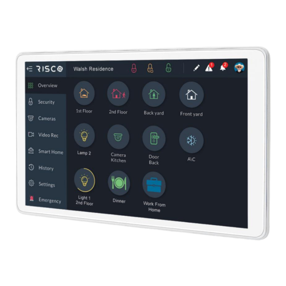
- Page 1 RisControl User Manual Model: RP432KPTZ...
-
Page 2: Table Of Contents
Step 8b – Adding Slaves to the Master Smart Home Gateway ......23 Step 8c – Slave Smart Home Gateway Installer Setup .......... 24 Step 9: Synchronizing the RisControl with the Security Setup ......25 OPERATING THE RISCONTROL ................... 26 Entering RisControl .................... - Page 3 About the Lock Screen....................35 Lock Screen with Quick Arm and/or Quick Stay ............36 Lock Screen with Undefined Quick Buttons .............. 37 The Lock Screen during Incoming Alarm ..............38 Blank Display Mode ....................39 OVERVIEW SCREEN ....................40 Using the Overview Screen ..................
- Page 4 Language ........................75 System Information ....................75 Manual (Software) Update ................... 75 RisControl Software Version ................. 77 RisControl IP Address & MAC ................77 Security System SW Version.................. 77 Security System IP Address ................... 77 RisControl Bus ID ....................77 Users and Permission Settings ...................
- Page 5 Restart Keypad ..................... 84 Upload Logs File ....................84 Anti-Code ......................85 Monitoring Station ....................86 Sounds ........................86 Follow Me ........................87 Adding a Follow Me Recipient ................87 Test or Edit a Follow Me ..................88 Service Info ........................ 88 RULES ........................
-
Page 6: Introduction
RisControl is a high-resolution Smart Touchscreen Keypad with an intuitive, easy to navigate user interface. RisControl combines standard keypad functionality with the ability to operate RISCO’s cloud-based solutions and products, such as alarm, video and Smart Home devices, from one customizable screen. -
Page 7: Installing The Riscontrol
INSTALLING THE RISCONTROL Note: This chapter is intended for the installer. Mounting RisControl 1. Remove the RS 485 connector. 2. Insert the wires into the RS Wall Installation 485 connector and secure with screws. - Page 8 3 Gang Flush Mounting Box Installation 3. Remove screw to separate the bracket from the RisControl.
- Page 9 4. Push down and then outward to remove the bracket. 5. Position the bracket on the Wall Installation wall / Flush Mounting Box and secure with 5 screws including tamper (Wall installation) / 3 screws including tamper (Flush Mounting Box installation).
- Page 10 3 Gang Flush Mounting Box Installation 6. Insert the RS 485 connector into its location in the rear side of the RisControl. 7. Position the 4 grooves of the RisControl over the bracket’s 4 pins and slide downward to secure.
-
Page 12: Riscontrol Setup
Step 1: Selecting the language for the RisControl • Step 2: Setting the Bus Address (Virtual DIP Switch) • Step 3: Setting the Wi-Fi connection – for connecting the RisControl to the RISCO Cloud (optional) • Step 4: Synchronizing the RisControl with the Security Setup Step 1: Selecting the language for the RisControl When the "Welcome"... -
Page 13: Step 3: Setting The Wi-Fi Connection (Optional)
Following address setup of the RisControl, click “NEXT”. Note: The setup procedure will continue in parallel with the time it takes for the RisControl to be added to the Security System (that has not yet “discovered” the other RisControl on the bus). - Page 14 Figure 4: Selecting a Wi-Fi Network Enter a password, to ensure Wi-Fi security Figure 5: Enter Password Note: If the unit is intended for Master Smart Home Gateway, it is required to connect to the Wi-Fi network. If not, this step is optional since the unit will operate as Slave Smart Home Gateway...
-
Page 15: Step 4A: Setup Slave/Master Smart Home Gateway
Master Smart Home Gateway only. Step 4b: Installer Login to RISCO Cloud Enter your RISCO Cloud Username and Password. Figure 7: Installer Login to RISCO Cloud Screen... -
Page 16: Step 5: Assigning A Site
Step 5: Assigning a Site The Master Smart Home Gateway must be assigned to a RISCO Cloud Site. Create a new site for the Master Smart Home Gateway or select an existing site. Figure 8: Assigning a Site to the Master Smart Home Gateway Screen Note: If the panel is already in an existing site, you will be directed automatically to Step 6. -
Page 17: Step 5A: Create A New Site
IMPORTANT! The following screen is displayed when the installer cannot use the control panel for the reasons mentioned on the screen. Click the “BACK” button and correct as required or click the “END” button to terminate the setup procedure. Figure 9: Important Security Panel Screen Step 5a: Create a New Site Enter the site details and then click the “NEXT”... -
Page 18: Step 5B: Enter Owner Details
Step 5b: Enter Owner Details Enter the owner’s email, name and phone number, and then click the “NEXT” button: Note: The owner is the Grand Master of the site Figure 10: Entering Owner Details Screen... -
Page 19: Step 5C: Select Existing Site
Step 5c: Select Existing Site Search for an existing site by the Site’s Name. Note: Relevant only for sites that are in your Company and for which you have permission to view. Figure 11: Selecting Existing Site Screen If there is more than one existing site, select an existing site from the displayed list. Figure 12: Selecting Existing Site from List Screen... -
Page 20: Step 6: Site Details
Step 6: Site Details Check the displayed site details and then click “NEXT” to confirm. Figure 13: Confirming Site Details Screen... -
Page 21: Step 7 - Entering Panel's Password
Step 7 – Entering Panel’s Password Enter the panel’s RISCO Cloud password and then enter it again to confirm. This ends the setup procedure for the Master Smart Home Gateway. Note: The Panel Password screen below will appear only if the panel is not already in the site. -
Page 22: Step 8A - Master Smart Home Gateway Installer Setup
Step 8a – Master Smart Home Gateway Installer Setup From the Settings Menu, select Installer Setup. Figure 15: Master Smart Home Gateway Installer Setup Screen Note: The “Master” state of the RISCO Smart Home Gateway can be changed only by performing Factory Reset to the unit. -
Page 23: Step 8B - Adding Slaves To The Master Smart Home Gateway
Step 8b – Adding Slaves to the Master Smart Home Gateway 1. In Enrolled Riscontrol Slaves, click the “View” button. The screen that opens displays a list of enrolled Slave Gateways in the Master Smart Home Gateway. 2. Perform one of the following: •... -
Page 24: Step 8C - Slave Smart Home Gateway Installer Setup
Step 8c – Slave Smart Home Gateway Installer Setup 1. After entering the RisControl using your Installer Code, go to Settings menu and select Installer Setup. 2. In Hosting Master, click the “Enroll” button to enroll this Slave Gateway to the Master Smart Home Gateway. -
Page 25: Step 9: Synchronizing The Riscontrol With The Security Setup
Configuration Software (CS) or a regular keypad to command the Security System to scan the RS-485 bus for new devices to allow the RisControl to connect to the Security System and begin synchronization. -
Page 26: Operating The Riscontrol
RisControl Main Menu The RisControl main menu, on the left side of the screen, allows the user to navigate the various menus, as required. The main menu is always displayed on the screen and the user can decide to use the expanded mode, where the text description of each menu appears next to the menu icon, or, in its collapsed mode, where only the icons of the menus appear. - Page 27 Figure 20: Main Menu (expanded mode) The user can use the button, at the top left corner of the screen, to change the menu mode of display. Here is how it looks when the display is collapsed: Figure 21: Main Menu (collapsed mode)
-
Page 28: Riscontrol Top Bar
Manual termination of the RisControl Session - If the End-User wishes to manually lock his open RISCO Cloud Session (to prevent the open screen of the RisControl from being used by an unauthorized user) the user can click the avatar and then click “Lock Screen”. -
Page 29: Troubles Management
Troubles Management Click the Trouble icon in the Top Bar of the RISCO Cloud to open a list of all the Troubles that exist in the system, as show in the example below. Note: The Trouble icon will appear only when there are Trouble messages. - Page 30 Figure 25: Communication Troubles Flow Troubles related to communication failure will be listed first and pinned to the top of the list. Click the “See Connection Status” button in the Troubles List; a popup is displayed, indicating the status of each of the connections. Figure 26: Communication Troubles Screen...
-
Page 31: Confirm Troubles
All restored troubles will disappear from the Trouble List. The other troubles will remain in the list. Notifications Management Click the Notifications icon in the Top Bar of the RisControl to open a list of all the notifications that are applicable to the RisControl, as shown in the example below. -
Page 32: Software Update Notification
Figure 28: Notification List Software Update Notification Whenever a Software Update is available, it will be pinned to the top of the list. The user can click the “Update Now” button to start the process or click the “Schedule Update” button for future update. Note: This procedure is similar to the one described in “System Information”... - Page 33 The following popup message will be displayed. Figure 29: Confirmed Alarms Screen Click the “OK” button, to approve the confirmation or “Cancel” to cancel it.
-
Page 34: Screen Saver
SCREEN SAVER The RisControl enters Screen Saver mode after a period of at least 45 seconds in which the screen has not been touched. In this case, RisControl will displays one of a variety of screens that is selected by the Grand Master (see page 74). -
Page 35: Lock Screen
The RisControl Lock Screen is the screen that the user sees following a predefined time period during which the screen has not been touched. The Lock Screen is to ensure that a user who has entered the RisControl with the PIN Code, does not make the RisControl available to unauthorized people. -
Page 36: Lock Screen With Quick Arm And/Or Quick Stay
Lock Screen with Quick Arm and/or Quick Stay The RisControl is always assigned to only one partition and can also be masked to other partitions, via the Installer Programing of the Security System. The partition that is assigned to the RisControl can be set (via the Installer Programming Menu) to allow Quick Arm and/or Quick Stay. -
Page 37: Lock Screen With Undefined Quick Buttons
Slide to unlock – - the user can slide the Lock Screen from left to right to open the Keypad and then enter a PIN Code to unlock the RisControl. • Emergency – The user can click the Emergency button... -
Page 38: The Lock Screen During Incoming Alarm
The Lock Screen during Incoming Alarm While in Lock Screen and when there is an alarm assigned to one or more partitions in RisControl, the Lock Screen will change to the following screen. Figure 35: Incoming Alarm in Lock Screen The Alarm indication will be accompanied with a beep sound. -
Page 39: Blank Display Mode
The user can also enter the RisControl while the alarm is activated by using the “Slide to unlock”. The user can then disarm the alarm or perform usual operations. Blank Display Mode Note: This section is applicable only to Security Systems in installations that must comply with European Norms (EN). -
Page 40: Overview Screen
OVERVIEW SCREEN A practical and time-saving feature of the RisControl is the Overview Screen. The Overview Screen allows each RisControl user to set shortcuts to all frequently used or favorite activities in one screen, without having to navigate multiple screens to access them. -
Page 41: Empty Overview Screen
Empty Overview Screen When a user unlocks the RisControl Lock Screen for the first time, by entering a valid PIN Code, an empty Overview Screen (one that does not have any shortcut buttons) is displayed, as shown below. Figure 38: Empty Overview Screen The user may want to leave the Overview Screen empty and not use the shortcuts. -
Page 42: Adding Shortcut Buttons To The Overview Screen
The user can add shortcut buttons to the Overview screen. Note: An Overview Screen that has at least one shortcut button will be the default screen that is displayed upon each unlocking of the RisControl. Click Add new button , the “Add Buttons to Overview Screen” will be displayed. - Page 43 Figure 40: Overview Screen – Adding Shortcut Buttons This screen is divided into the following side tabs: • Security • Cameras • Automation • Rules Adding Cameras Buttons to the Overview Screen Click the Cameras side tab to open the list of cameras. Click the bubble icons of the cameras that you wish to add to the Overview Screen.
- Page 44 Figure 41: Overview Screen – Adding Rules Buttons Partitions in the Overview Screen • A partition with a “V” inside a bubble icon will be added to the Overview screen • A partition with a blank bubble icon will not be added to the Overview screen...
-
Page 45: Removing Shortcut Buttons From The Overview Screen
Outputs to be added to his Overview Screen. These selections are personal and will be displayed on the Overview screen upon each entry of the RisControl and independent of the selection and preferences of the other users of the same RisControl. -
Page 46: Incoming Alarm On The Overview Screen
Incoming Alarm on the Overview Screen If an alarm is initiated in any of the partitions assigned to the RisControl (and that are associated with the user that is currently logged in), the alarm will appear as a floating button at the bottom right of the Overview Screen, as shown below. -
Page 47: Security
SECURITY The security section of the RisControl describes all the operations and activities relevant to the Security System. As in the Overview Screen, an initiated alarm will appear as a floating button at the bottom right of the Security Screen (except for the Security→Partitions screen). -
Page 48: Arming And Disarming
Stay=Orange Armed=Red Disarmed=Green Not ready=Gray Arming and Disarming The user can Full Arm, Stay Arm or Disarm any of the partitions on the screen. For example, if a user clicks a disarmed partition, a popup screen is displayed that allows the user to either Full Arm or Stay Arm the partition, as shown below. Figure 44: Arming a Partition Screen Note: If a Partition fails to arm, this will be indicated as shown below. -
Page 49: Exit/Entry Delay
A partition that is defined with an Exit/Entry delay will be indicated on the screen via a contour-line button. The time remaining will be displayed at the center of the button. In addition, a beeping sound will be heard via the RisControl throughout the Exit/Entry time. -
Page 50: One Click Activation Of All Partitions
One Click Activation of all Partitions There are three lock icon buttons at the top of the screen, as follows: • Red Lock Icon button: click to Full Arm all the partitions • Orange Lock Icon button: click to Stay Arm all the partitions •... -
Page 51: Arming/Disarming Selected Or All Partitions
Arming/Disarming Selected or All Partitions 1. Click the Partitions tab at the top of the screen; the following screen is displayed. Figure 46: Selecting Multiple Partitions Screen Click to select the partitions to be Armed or Disarmed; a “√” is added to the partition icon –... - Page 52 • Red: Full Arm • Gray: Not Ready Click the Groups tab; the following screen is displayed. Figure 47: Selecting Groups Screen Click the Group letter button corresponding to the Group/s you want to arm; the following screen displays the partitions in the available Groups to be armed. Figure 48: Selecting Groups Partitions Screen...
-
Page 53: Detectors
Select the required Partitions and then click the “Arm” button. Note: You can check/uncheck the ‘All Partitions” box to select/deselect all Partitions by a single action. The Group icon status indications (see above) also apply to the Groups Partitions screen. Note: If after clicking the “Arm”... -
Page 54: Utility Outputs
Figure 50: Detector Setup Screen Note: For a detailed definition of the Bypass and the Presence Notifications, refer to the Security System’s Installation Manual. Utility Outputs On the Utility Outputs Screen, click the relevant Utility Output button to operate that output. Figure 51: Utility Outputs Screen... -
Page 55: Cameras
The camera section lists all the cameras that are used in the system, including: • Video cameras that are connected directly to the RISCO Cloud • Video cameras that are connected to the RISCO Cloud through a RISCO Video Recorder • PIRCAMs that are connected through the RISCO Security System... -
Page 56: Pir Cam
• Video Camera through a Video Recorder Note: Connection through a Video Recorder is indicated by the dot inside the camera icon. PIR CAM Click any of the PIR CAMs in the screen to view the images take by that camera. Figure 53: PIR Camera Image View Click the “Take Photo”... -
Page 57: Video Cameras
However, the user’s own voice will be muted and will not be heard via the camera. Click the icon at the top of the screen to cancel the mute operation of the RisControl microphone. Use the Quick Buttons to perform selected activities, (see Quick Buttons, page 59). -
Page 58: The Cameras Screen
Figure 55: Cameras connected to the RISCO Cloud By clicking on a camera icon of a RISCO Video Recorder, the live view of the camera is displayed. Cameras that are connected to the RISCO Video Recorder can also switch to show pre-recorded video clips (see Video Recorder, page 62). -
Page 59: Quick Buttons
Note: A user can individually set the exact combination of Quick Buttons that will appear in the Quick Buttons Tray; separately for each camera and independent of the Quick Buttons’ selection of other users in the same RisControl. Editing the Quick Buttons Tray Every user can individually select the Quick Buttons to be displayed in the Quick Buttons Tray of a camera that the user is watching. -
Page 60: Adding/Removing Quick Buttons From The Tray
Adding/Removing Quick Buttons from the Tray Upon entering the edit mode of the Quick Buttons Tray, all the Quick Buttons will appear with an “x” bubble on them. To remove the Quick Button from the tray, click the “x” bubble of the Quick Button. - Page 61 Figure 59: Editing the List of Quick Buttons 3. Select the “Apply to all” box to set the current selection of Quick Buttons to all the cameras for which the user has permissions.
-
Page 62: Video Recorder
Video Recorder. Note: The user must be logged into the RISCO Cloud via the RisControl to be able to watch playback on the Video Recorder. - Page 63 To change the Live Gallery Image Layout, click the buttons located above the images: . The selected layout will be remembered by the RisControl separately for each user. Figure 62: Video Rec – Live Gallery Image Layouts The Gallery displays a matrix of live videos taken from cameras, with the camera...
-
Page 64: Camera Video Playback
Camera Video Playback To watch recorded video clips from any given camera, click the camera image in the Gallery, as shown in the example below. Figure 63: Playback Screen Time Slider The Time Slider that appears under an image, provides the exact time each video clip was recorded. -
Page 65: Playback Controls
Time Slider Center Pointer – the pointer at the center of the Time Slider is fixed, showing the exact time that it points to at each moment. Use your finger to slide the Time Slider left of right, until the Center Pointer points to the exact required time. -
Page 66: Switch Back To Live
Switch back to Live Click the “Switch to Live” button at any time to switch the view from Playback to Live camera mode. -
Page 67: Smart Home
SMART HOME RisControl supports the RISCO Smart Home that allows you to control and schedule the operation of automation devices in your home and office. Using a Smart Home Device Click the side tab; the following screen is displayed. Figure 66: Smart Home Groups Tab Screen Devices can be displayed according to defined groups in the system or according to defined types, depending on the selected tabs. -
Page 68: Device Buttons Operations
Figure 67: Smart Home Devices Type Screen You can search for groups of specific devices by entering the device name. The groups containing the searched device name or part of the name will be displayed. Device Buttons Operations From the list of device types, select a smart home device (see example below). Figure 68: Smart Home Device Operation Screen1 Swipe the small button at the bottom of the screen left or right to move to the next screen. - Page 69 Note: Some device screens will display more than two small buttons that correspond to the number of screens for that specific device. Figure 69: Smart Home Device Operation Screen2 Button Description Device Name Name assigned to device Icon with status For example, On/Off/dim percentage level Info Displays device information...
-
Page 70: History
RisControl can store up to 2000 events. These events are logged in chronological order according to date and time. When the event log exceeds the maximum of 2,000 events, the oldest events are overwritten by the newest events. -
Page 71: Media Events
Select a category to filter the search according to specific types of events Media Events You can view captured snapshot images or video clips recorded during specific related alarm events. Click the “Media Events” option, search for the event and then click on the event to view. -
Page 72: Settings
SETTINGS The Settings Menu displays the System Settings Screen, as shown in the example below. This screen is used for defining RisControl parameters and defining date and time settings. Figure 71: Settings Menu Screen Note: All the Menu options are available only to the Grand Master of the system. -
Page 73: General
Figure 72: Settings Menu - General Wi-Fi Connection Click the Wi-Fi connection option to connect the RisControl to a Wi-Fi router that is connected to the Internet. The RisControl will search for available networks and allow the user to select one of them. -
Page 74: Session Timeout
Click the “Screen Saver” option; the following screen is displayed. Figure 74: Screen Saver Selection Select one of the options, and then click the “Set Screen Saver” button; the selected Screen Saver will appear for as long as RisControl is in the Screen Saver state. Screen Saver Options: •... -
Page 75: Language
Click the “Language” option and select the desired language from the list. The language selection is applicable only to the RisControl that is being set up and is not applicable to the other RisControl units, or to the language of the Security System. - Page 76 31). After the new software version is downloaded but is not yet installed, the RisControl will prompt the user to install it. If the user selects to install the downloaded version, RisControl will perform the procedure and then self-restart...
-
Page 77: Riscontrol Software Version
Displays the IP Address of the Security System. RisControl Bus ID The RisControl BUS ID displays the Bus Address (Virtual DIP Switch) of the panel. Users and Permission Settings The Grand Master and Master Users can add users to the Security System from the RisControl. -
Page 78: Add A User
Add a User You can add a New User to the system. From the Settings Menu, click “Users & Permissions”. A list is displayed of the Grand Master or Master User and all the users under this level. The Grand Master or Master User can edit any existing user. Other users can only view their own name that is listed with restrictions to the type of editing that can be performed. -
Page 79: Edit Or Delete A User
Edit or Delete a User The Grand Master or Master User can edit or delete any of the users that are in their list. ➢ To edit a user: Click “Users & Permissions” and select a user that you want to edit. Perform the required changes and click the “Save”... -
Page 80: Login To The Risco Cloud
1. The username and password will be remembered for future login attempts, without the need to reenter credentials. 2. Upon each entry of the PIN Code in the RisControl, the user will also be automatically logged into the RISCO Cloud. -
Page 81: Date & Time
Figure 82: Login to the RISCO Cloud Screen Date & Time Selecting the Settings menu displays the Date & Time Screen, as shown in the screen below. This screen is used for defining date and time settings for the RisControl. -
Page 82: Date & Time Settings
When the “Sync Date & Time with Panel” toggle button is turned off, the RisControl manages its own date and time. In this case, the user can define the date and time settings and format. -
Page 83: Walk Test
3. Walk through and trip the zones that are being tested. The tripped zones that are identified by the Security System will be listed in the RisControl screen. These zones indicate that the zones are responsive and are, therefore, detectable. -
Page 84: Siren Test
Click the “ACTIVATE” button to activate “Service Mode”. Replace the device batteries, as required. Restart Keypad Click the “RESTART” button to restart the RisControl Keypad. Upload Logs File You can upload log files to a predefined storage location, where access to these files will be given to RISCO support. -
Page 85: Anti-Code
SETTINGS/MAINTENANCE screen in the RisControl, and enter the Anti Code, as described below. Note: The Anti Code feature must be enabled by the installer in the panel. -
Page 86: Monitoring Station
Key tones • Chime Click “Sounds” in the Settings Menu; the following screen is displayed. Figure 89: Sound Settings Screen Drag to set the volume of the RisControl speaker (also increases/decreases all the sounds that are generated by the RisControl). -
Page 87: Follow Me
Follow Me The user can add Follow Me recipients, up to the limit defined in the panel. Adding a Follow Me Recipient Enter the “Follow Me” option of the Maintenance and click the “+” button at the top bar. Figure 90: Follow Me Screen The following screen is displayed. -
Page 88: Test Or Edit A Follow Me
To edit or send a test message, click the “Test” or “Edit” button in the Follow Me List. Service Info Click Service info to view the contact details of the installation company defined in the control panel or iRISCO app (if the RisControl is connected to the RISCO Cloud). Figure 92: Service Info Screen... -
Page 89: Rules
RULES Rules allow you to operate a pre-set sequence of alarm commands and smart home devices. Rules can be triggered by manually pressing a button, by a daily, weekly or monthly schedule or by system events. There are three types of rules, as follows: •... -
Page 90: Manual Rule
Figure 94: Rules Screen Click the “Add New Rule” button or the “+” button (on the top right); the Rules Wizard opens. Manual Rule Figure 95: Add New Rule Settings Screen In the “Name field”, enter a suitable name for the rule. -
Page 91: Schedule Rule
Under “Trigger”, select Manual. Under “Icon” select an icon and then select a color for the icon from the displayed colors; the icon’s color will now change to the selected color. Click “NEXT”; the ACTIONS screen is displayed Go to Performing Actions to continue (page 100). Schedule Rule Figure 96: Schedule Rule Screen In the “Name field”, enter a suitable name for the rule. - Page 92 • Between Dates – allows you to enable the rule for a set time period during the year. For example, summertime or wintertime. Choosing this option will open new fields to select start and end dates. Under “Icon” select an icon and then select a color for the icon from the displayed colors;...
- Page 93 Daily Schedule The daily schedule allows the rule to be activated at a start time every “x” number of days, as defined. Figure 98: Defining Daily Schedule Screen Select Daily Under “Rule start time”, click the drop-down list and select one of the following options and then enter the rule start time in the provided field.
- Page 94 IMPORTANT! The sunrise/sunset rule start time will be available only if the RisControl is connected to the RISCO Cloud, and the site address is properly configured in the RISCO Cloud. Figure 99: Rule Trigger Start Time Screen Note: Sunrise and sunset times will be set according to the site location defined by the installer.
- Page 95 Weekly Schedule The weekly schedule allows the rule to be activated at a start time on specific days of the week. Figure 100: Defining Weekly Schedule Screen Select Weekly. Under “Rule start time”, click the drop-down list and select one of the available options and then enter the rule start time in the provided field.
- Page 96 Monthly Schedule The monthly schedule allows the rule to be activated at a start time and date every “x” number of months, as defined. Figure 101: Defining Monthly Schedule Screen Select Monthly. Under “Rule start time”, click the drop-down list and select one of the available options and then enter the rule start time in the provided field.
-
Page 97: Event Rule
Event Rule Figure 102: Event Rule Screen In the “Name field”, enter a suitable name for the rule Under “Trigger”, select Event. Rule Active defines the time period during which the rule will be active. Select the Rule Active time period: •... - Page 98 Figure 103: Event Rule Trigger Screen Select to activate the rule when: an alarm system event occurs; upon detection event when alarm is disarmed; or when a smart device changes status. Under “Rule Works”, click the drop-down list and select one of the available options: •...
- Page 99 Figure 104: Alarm System Event Selection Screen Select an alarm/disarm for the event and then click the “ADD PARTITION” button. Figure 105: Alarm System Event Partition Selection Screen 10. Select a partition to assign to the event and then Click “Next”. Go to Performing Actions to continue (page 100).
-
Page 100: Performing Actions
Performing Actions Actions allow you to automatically arm/disarm selected partitions in different modes. You can also activate smart home devices and utility outputs. In addition, the time sequence of actions can be delayed from one action to the next. To Arm/Disarm Figure 106: Add New Rule –... - Page 101 Select the Delayed Action checkbox to delay the action and then enter the delay time in the provided field. Select from the available partitions. If Group Arm was selected, also select the Groups (A—D) to be armed per partition. Figure 108: Actions – Add Arm / Disarm Group Selection Screen Click the “SAVE”...
- Page 102 Figure 110: Actions – Automation Select Device Screen Click the Group arrow and select the Group/Groups to apply the smart device activation. Select the Delayed Action checkbox to delay the smart device activation and then enter the delay time in the provided field. Select one of the available devices and then click “Next”.
-
Page 103: View Rules Summary
Figure 112: Actions – Automation Device Example Screen You can now click “NEXT” to go to SUMMARY, click to make changes to the device or click to delete the device from the rule. View Rules Summary You can view a summary of the rules settings before saving the rule. Note: The Summary screen varies according to Manual / Schedule / Event Trigger. - Page 104 Figure 113: Actions Summary Screen If the viewed information is correct; click the “SAVE RULE” button. The saved rule will now appear on the Rules opening screen. Figure 114: Rules Screen...
-
Page 105: Set Night Mode
Set Night Mode Night Mode is used when the activation of a device follows the triggering of an event condition only during nighttime. For example, switching on a light switch during the night. You can set specific time parameters to designate Night Mode. From the Rules screen above , click the “Set Night Mode”... - Page 106 Figure 116: Set Time Screen Set the time for the start/end of Night Mode (from 00:00 to 23:59). Click the “OK” button. To Set Night Mode before/after Sunset/Sunrise: Click the dropdown list and select either Before Sunrise, After Sunrise, Before Sunset or After Sunset.
- Page 107 Figure 118: Set Night Start Time and End Time Screen Click the “SAVE” button.
-
Page 108: Set Vacation
Set Vacation A vacation is a schedule for automatic system arming/disarming for which you assign vacation-specific criteria as needed, such as dates/times. The start vacation will arm the system and will only be disarmed at the end of the vacation schedule. From the Rules screen above (see Figure 114: Rules Screen), click the “Set Vacation”... - Page 109 Figure 121: Set End Date and Time Note: The last date on the screen indicates the end date and dates in between the start and end dates are enclosed in open-ended rectangles – even if the end date is in a different month to the start date. Click the “Save”...
-
Page 110: Emergency
EMERGENCY The Emergency button appears at the top of the Lock Screen, at the end of the Main Menu. Note: The Emergency button will appear on the screen only if Emergency Keys was enabled by the installer in the panel. Figure 123: Emergency Button Screen Emergency Button Position in Lock Screen/Main Menu Click the Emergency button... -
Page 111: Specifications
1xmic Connections USB – 1xtype C USB Jack RS-485 – detachable terminal block Tamper 1xTamper Standard EN50131-3, Grade 3 Environmental Class II, PD 6662:2017 RP432KPTZAUA RisControl+ZWave for AU RP432KPTZEUA RisControl+ZWave for EU RP432KPTZILA RisControl+ZWave for IL RP432KPTZUSA RisControl+ZWave for US... -
Page 112: Red Compliance Statement
UKCA and CE RED Compliance Statement: Hereby, RISCO Group declares that this equipment is in compliance with the essential requirements of the UKCA Radio Equipment Regulations 2017 and CE Directive 2014/53/EU. For the UKCA and CE Declaration of Conformity please refer to our website: www.riscogroup.com... - Page 113 RISCO, for a period of (i) 24 months from the date of delivery of the Product (the “Warranty Period”). This Limited Warranty covers the Product only within the country where the Product was originally purchased and only covers Products purchased as new.
- Page 114 WARRANTY APPLICABLE THERETO, IF ANY, IS THE BATTERY MANUFACTURER'S WARRANTY. RISCO does not install or integrate the Product in the end user’s security system and is therefore not responsible for and cannot guarantee the performance of the end user’s security system which uses the Product or which the Product is a component of.
- Page 115 RISCO Group. The information contained herein is for the purpose of illustration and reference only.
- Page 116 Tel: +33-164-73-28-50 Tel: +34-91-490-2133 support-fr@riscogroup.com support-es@riscogroup.com This RISCO product was purchased at: © RISCO Group 2022. All rights reserved. No part of this document may be reproduced in any form without prior written permission from the publisher. 08/2022 5IN2941 B...
Need help?
Do you have a question about the RisControl and is the answer not in the manual?
Questions and answers