Table of Contents
Advertisement
Quick Links
Advertisement
Table of Contents

Subscribe to Our Youtube Channel
Related Manuals for Risco RP432KPTZAUA


Summary of Contents for Risco RP432KPTZAUA
- Page 1 RisControl User Manual Model: RP432KPT...
-
Page 2: Table Of Contents
Contents INTRODUCTION ......................5 INSTALLING THE RISCONTROL ..................6 Mounting the RisControl ....................6 RisControl Setup ......................10 Step 1: Selecting the language for the RisControl ..........10 Step 2: Setting the Bus Address (Virtual DIP Switch) ..........11 Step 3: Setting the Wi-Fi Connection (optional) ........... 12 Step 4: Synchronizing the RisControl with the Security Setup ...... - Page 3 Using the Shortcut Buttons from the Overview Screen ..........34 Incoming Alarm on the Overview Screen ..............35 SECURITY ........................36 Partitions ........................36 Arming and Disarming ..................37 Exit/Entry Delay ....................38 Final Exit Zone ...................... 38 One Click Activation of all Partitions ..............39 Arming/Disarming Selected or All Partitions ............
- Page 4 Users and Permission Settings ................... 64 Add a User ......................65 Edit or Delete a User ..................... 66 Edit a User’s Own Details ..................66 Login to the RISCO Cloud ..................67 Date & Time ....................... 68 Date & Time Settings..................... 69 Maintenance ......................69 The Maintenance Menu ..................
-
Page 5: Introduction
RisControl is a high-resolution Smart Touchscreen Keypad with an intuitive, easy to navigate user interface. RisControl combines standard keypad functionality with the ability to operate RISCO’s cloud-based solutions and products, such as alarm, video and Smart Home devices, from one customizable screen. -
Page 6: Installing The Riscontrol
INSTALLING THE RISCONTROL Note: This chapter is intended for the installer. Mounting RisControl 1. Remove the RS 485 connector. 2. Insert the wires into the RS 485 Wall Installation connector and secure with screws. - Page 7 3 Gang Flush Mounting Box Installation 3. Remove screw to separate the bracket from the RisControl.
- Page 8 4. Push down and then outward to remove the bracket. 5. Position the bracket on the Wall Installation wall / Flush Mounting Box and secure with 5 screws including tamper (Wall installation) / 3 screws including tamper (Flush Mounting Box installation).
- Page 9 3 Gang Flush Mounting Box Installation 6. Insert the RS 485 connector into its location in the rear side of the RisControl. 7. Position the 4 grooves of the RisControl over the bracket’s 4 pins and slide downward to secure.
-
Page 10: Riscontrol Setup
Step 1: Selecting the language for the RisControl • Step 2: Setting the Bus Address (Virtual DIP Switch) • Step 3: Setting the Wi-Fi connection – for connecting the RisControl to the RISCO Cloud (optional) • Step 4: Synchronizing the RisControl with the Security Setup Step 1: Selecting the language for the RisControl When the "Welcome"... -
Page 11: Step 2: Setting The Bus Address (Virtual Dip Switch)
Figure 2: Welcome Screen Step 2: Setting the Bus Address (Virtual DIP Switch) Set the virtual toggle switches on the screen below to indicate the BUS address of the RisControl. For detailed instructions, refer to your receiver’s installation manual, Setting BUS Accessories ID Numbers section. Note: The RisControl will not communicate by BUS until prompted by the panel following the "Scan for devices"... -
Page 12: Step 3: Setting The Wi-Fi Connection (Optional)
Note: The connection to the Wi-Fi can also be performed by the end-user at a later time. 1. From the screen that appears, select a Wi-Fi network from the list. Note: If RISCO Cloud connection is not required, click the "Skip" button. - Page 13 Figure 4: Selecting a Wi-Fi Network Enter a password, to ensure Wi-Fi security Figure 5: Enter Password After the RisControl is connected to the router successfully and with the router connected to the Internet, the RisControl will be now connected to the RISCO Cloud.
-
Page 14: Step 4: Synchronizing The Riscontrol With The Security Setup
Step 4: Synchronizing the RisControl with the Security Setup Following setup of the Bus Address (Step 2) and before the setup procedure is completed successfully, the installer must use the Configuration Software (CS) or a regular keypad to command the Security System to scan the RS-485 bus for new devices to allow the RisControl to connect to the Security System and begin synchronization. -
Page 15: Operating The Riscontrol
OPERATING THE RISCONTROL Entering RisControl The RisControl operates most of the time in “Screen Saver” mode (see SCREEN SAVER, page 24). When the user can clicks anywhere on the screen, the RisControl will exit the Screen Saver mode and switch to the “Lock Screen” (page 25). To unlock the “Lock Screen”, the user must type a valid PIN Code. -
Page 16: Riscontrol Top Bar
Figure 8: Main Menu (expanded mode) The user can use the button, at the top left corner of the screen, to change the menu mode of display. Here is how it looks when the display is collapsed: Figure 9: Main Menu (collapsed mode) RisControl Top Bar The “RisControl Top Bar”... - Page 17 The End-User’s Avatar The End-User’s Avatar appears at the top bar of all the screens. Each user can select his own avatar as described in “Users and Permission Settings”, “...
- Page 18 Manual termination of the RisControl Session - If the End-User wishes to manually lock his open RISCO Cloud Session (to prevent the open screen of the RisControl from being used by an unauthorized user) the user can click the avatar and then click “Lock Screen”.
-
Page 19: Troubles Management
Troubles Management Click the Trouble icon in the Top Bar of the RISCO Cloud to open a list of all the Troubles that exist in the system, as show in the example below. Note: The Trouble icon will appear only when there are Trouble messages. - Page 20 Figure 13: Communication Troubles Flow Troubles related to communication failure will be listed first and pinned to the top of the list. Click the “See connection status” button in the Troubles List; a popup is displayed, indicating the status of each of the connections. Figure 14: Communication Troubles Screen...
-
Page 21: Confirm Troubles
Confirm Troubles Note: This section is applicable only to Grade-2 and Grade-3 installations. Users of lower grade installations can skip to the next section. Some of the troubles in Grade-2 and Grade-3 installations must be “confirmed” by the user. When such troubles exist in the system, the “Confirm all troubles” button will appear at the bottom of the trouble list. -
Page 22: Software Update Notification
Figure 16: Notification List Software Update Notification Whenever a Software Update is available, it will be pinned to the top of the list. The user can click the “Update Now” button to start the process or click the “Schedule Update” button for future update. Note: This procedure is similar to the one described in “System Information”... - Page 23 The following popup message will be displayed. Figure 17: Confirmed Alarms Screen Click the “OK” button, to approve the confirmation or “Cancel” to cancel it.
-
Page 24: Screen Saver
SCREEN SAVER The RisControl enters Screen Saver mode after a period of at least 45 seconds in which the screen has not been touched. In this case, RisControl will displays one of a variety of screens that is selected by the Grand Master (see page 61). Figure 18: Screen Saver Exit/Entry Screen Saver Mode To exit the Screen Saver mode, simply touch the screen. -
Page 25: Lock Screen
LOCK SCREEN About the Lock Screen The RisControl Lock Screen is the screen that the user sees following a predefined time period during which the screen has not been touched. The Lock Screen is to ensure that a user who has entered the RisControl with the PIN Code, does not make the RisControl available to unauthorized people. -
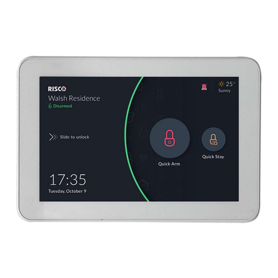
Page 26: Lock Screen With Quick Arm And/Or Quick Stay
Lock Screen with Quick Arm and/or Quick Stay The RisControl is always assigned to only one partition and can also be masked to other partitions, via the Installer Programing of the Security System. The partition that is assigned to the RisControl can be set (via the Installer Programming Menu) to allow Quick Arm and/or Quick Stay. -
Page 27: Lock Screen With Undefined Quick Buttons
RisControl’s Assigned Partition Status - Assigned Partition status is always indicated at the top left corner of the Lock Screen and by the color of the arc at the middle of the Lock Screen, as follows: • Green – assigned partition is disarmed •... -
Page 28: The Lock Screen During Incoming Alarm
Figure 22: Quick Buttons not Defined in Lock Screen In this state, the user can enter the PIN Code only to unlock and enter the RisControl and to click the Emergency button, in case of emergency. The Lock Screen during Incoming Alarm While in Lock Screen and when there is an alarm assigned to one or more partitions in RisControl, the Lock Screen will change to the following screen. -
Page 29: Blank Display Mode
The user can also enter the RisControl while the alarm is activated by using the “Slide to unlock”. The user can then disarm the alarm or perform usual operations. Blank Display Mode Note: This section is applicable only to Security Systems in installations that must comply with European Norms (EN). -
Page 30: Overview Screen
OVERVIEW SCREEN A practical and time-saving feature of the RisControl is the Overview Screen. The Overview Screen allows each RisControl user to set shortcuts to all frequently used or favorite activities in one screen, without having to navigate multiple screens to access them. Using the Overview Screen When the user unlocks the RisControl with the PIN Code, the Overview Screen opens, as shown below. -
Page 31: Empty Overview Screen
Empty Overview Screen When a user unlocks the RisControl Lock Screen for the first time, by entering a valid PIN Code, an empty Overview Screen (one that does not have any shortcut buttons) is displayed, as shown below. Figure 26: Empty Overview Screen The user may want to leave the Overview Screen empty and not use the shortcuts. -
Page 32: Adding Shortcut Buttons To The Overview Screen
Figure 27: Overview Screen – Edit Mode Adding Shortcut Buttons to the Overview Screen The user can add shortcut buttons to the Overview screen. Note: An Overview Screen that has at least one shortcut button will be the default screen that is displayed upon each unlocking of the RisControl. Click the , the “Add Buttons to Overview Screen”... - Page 33 Figure 28: Overview Screen – Adding Shortcut Buttons This screen is divided into the following side tabs: • Security • Cameras • Utility Outputs Adding Cameras to the Overview Screen Click the side tab to open the list of cameras. Click the bubble icons of the cameras that you wish to add to the Overview Screen.
-
Page 34: Removing Shortcut Buttons From The Overview Screen
Note: The user can click the bubble icons of Partitions, Cameras and Utility Outputs to be added to his Overview Screen. These selections are personal and will be displayed on the Overview screen upon each entry of the RisControl and independent of the selection and preferences of the other users of the same RisControl. -
Page 35: Incoming Alarm On The Overview Screen
Incoming Alarm on the Overview Screen If an alarm is initiated in any of the partitions assigned to the RisControl (and that are associated with the user that is currently logged in), the alarm will appear as a floating button at the bottom right of the Overview Screen, as shown below. Figure 29: Incoming Alarm Floating Button The name of the Zone/Partition that triggered the alarm is indicated under the floating button. -
Page 36: Security
SECURITY The security section of the RisControl describes all the operations and activities relevant to the Security System. As in the Overview Screen, an initiated alarm will appear as a floating button at the bottom right of the Security Screen (except for the Security→Partitions screen). Partitions The Security→Partitions screen is the default screen that is displayed after the user clicks the “Security”... -
Page 37: Arming And Disarming
Stay=Orange Armed=Red Disarmed=Green Not ready=Gray Arming and Disarming The user can Full Arm, Stay Arm or Disarm any of the partitions on the screen. For example, if a user clicks a disarmed partition, a popup screen is displayed that allows the user to either Full Arm or Stay Arm the partition, as shown below. Figure 31: Arming a Partition Screen Note: If a Partition fails to arm, this will be indicated as shown below. -
Page 38: Exit/Entry Delay
Figure 32: Partition Failed to Arm Screen Exit/Entry Delay A partition that is defined with an Exit/Entry delay will be indicated on the screen via a contour-line button. The time remaining will be displayed at the center of the button. In addition, a beeping sound will be heard via the RisControl throughout the Exit/Entry time. -
Page 39: One Click Activation Of All Partitions
One Click Activation of all Partitions There are three lock icon buttons at the top of the screen, as follows: • Red Lock Icon button: click to Full Arm all the partitions • Orange Lock Icon button: click to Stay Arm all the partitions •... -
Page 40: Arming/Disarming Selected Or All Partitions
Arming/Disarming Selected or All Partitions 1. Click the “Partitions” tab at the top of the screen; the following screen is displayed. Figure 33: Selecting Multiple Partitions Screen Click to select the partitions to be Armed or Disarmed; a “√” is added to the partition icon –... - Page 41 • Red: Full Arm • Gray: Not Ready Click the Groups tab; the following screen is displayed. Figure 34: Selecting Groups Screen Click the Group letter button corresponding to the Group/s you want to arm; the following screen displays the partitions in the available Groups to be armed. Figure 35: Selecting Groups Partitions Screen...
-
Page 42: Detectors
Select the required Partitions and then click the “Arm” button. Note: You can check/uncheck the ‘All Partitions” box to select/deselect all Partitions by a single action. The Group icon status indications (see above) also apply to the Groups Partitions screen. Note: If after clicking the “Arm”... - Page 43 Figure 37: Detector Setup Screen Note: For a detailed definition of the Bypass and the Presence Notifications, refer to the Security System’s Installation Manual.
-
Page 44: Utility Outputs
Utility Outputs On the Utility Outputs Screen, click the relevant Utility Output button to operate that output. Figure 38: Utility Outputs Screen... -
Page 45: Cameras
The camera section lists all the cameras that are used in the system, including: • Video cameras that are connected directly to the RISCO Cloud • Video cameras that are connected to the RISCO Cloud through a RISCO Video Recorder • PIRCAMs that are connected through the RISCO Security System... -
Page 46: Pir Cam
• Video Camera through a Video Recorder Note: Connection through a Video Recorder is indicated by the dot inside the camera icon. PIR CAM Click any of the PIR CAMs in the screen to view the images take by that camera. Figure 40: PIR Camera Image View Click the “Take Photo”... -
Page 47: Video Cameras
Video Cameras Click any of the P2P Cameras in the screen to view live video from that camera. Figure 41: P2P Camera Live Video Screen From the Live Video screen of the P2P camera, the user will be able to hear audio from the camera’s microphone. -
Page 48: The Cameras Screen
Figure 42: Cameras connected to the RISCO Cloud By clicking on a camera icon of a RISCO Video Recorder, the live view of the camera is displayed. Cameras that are connected to the RISCO Video Recorder can also switch to show pre-recorded video clips (see Video Recorder, page 52). -
Page 49: Quick Buttons
Quick Buttons Using Quick Buttons The area at the bottom of the screen, that displays the images or video clips from the various camera types, is referred to as the “Quick Buttons Tray”. Figure 44: Quick Buttons Tray Quick Buttons Tray The Quick Buttons Tray allows the user to perform activities while viewing the image and or video clip. -
Page 50: Adding/Removing Quick Buttons From The Tray
Adding/Removing Quick Buttons from the Tray Upon entering the edit mode of the Quick Buttons Tray, all the Quick Buttons will appear with an “x” bubble on them. To remove the Quick Button from the tray, click the “x” bubble of the Quick Button. - Page 51 Figure 46: Editing the List of Quick Buttons 3. Select the “Apply to all” box to set the current selection of Quick Buttons to all the cameras for which the user has permissions.
-
Page 52: Video Recorder
Video Recorder. Note: The user must be logged into the RISCO Cloud via the RisControl to be able to watch playback on the Video Recorder. -
Page 53: Camera Video Playback
Figure 48: Video Rec Live Gallery Screen - 2x2 image layout To change the Live Gallery Image Layout, click the buttons located above the images: . The selected layout will be remembered by the RisControl separately for each user. Figure 49: Video Rec – Live Gallery Image Layouts The Gallery displays a matrix of live videos taken from cameras, with the camera name indicated on each video (empty areas are darkened). -
Page 54: Time Slider
Figure 50: Playback Screen Time Slider The Time Slider that appears under an image, provides the exact time each video clip was recorded. Figure 51: Time Slider Screen Time Slider coverage range - The slider is set to cover 24 hours, from 00:00:00 to 23:59:59 of the current date, by default. -
Page 55: Playback Controls
Video clip indications on the slider – Recorded video clips are indicated on the Time Slider using blue ticks. See the following example of 3 clips that were recorded: Playback Controls There are four standard playback control buttons, as follows: Figure 52: Playback Control Buttons Play Click to play the “next clip”, i.e. -
Page 56: Smart Home
SMART HOME RisControl will support the RISCO Smart Home in a future RisControl version. -
Page 57: History
HISTORY Selecting the History Menu displays the History Screen, as shown in the example below. This screen is used for the viewing a history log of events. For each event you can view the date and time that the event occurred, a description of the event and the detector or device that caused the event. -
Page 58: Media Events
Select a category to filter the search according to specific types of events Media Events You can view captured snapshot images or video clips recorded during specific related alarm events. Click the “Media Events” option, search for the event and then click on the event to view. -
Page 59: Settings
SETTINGS The Settings Menu displays the System Settings Screen, as shown in the example below. This screen is used for defining RisControl parameters and defining date and time settings. Figure 54: Settings Menu Screen Note: All the Menu options are available only to the Grand Master of the system. Only the “Users &... -
Page 60: General
The RisControl will search for available networks and allow the user to select one of them. Note: RisControl can be used without connection to the RISCO Cloud. In this case, most operations that are applicable to the Security System will be available, except for Cameras, Video Recorders and other cloud related features that are not supported. -
Page 61: Session Timeout
Session Timeout The RisControl will automatically lock following a predefined “idle” time (Session Timeout) during which the screen has not been touched. The Grand Master can select between 15, 30- or 40-seconds session timeout. Click the Session Timeout option in the menu. Select the preferred duration. -
Page 62: Language
Manual (software) update is performed by the Grand Master and is applicable only to a RisControl that is connected to the Internet through the Wi-Fi network. Click the “Check for Update” button; if an update is available, the following RISCO Cloud screen is displayed. - Page 63 Figure 59: Software Update Screen Click the “Update Now” button; a download of the updated software version is initiated. Note The downloaded version is not installed automatically but must be initiated by the Grand Master. If a search for updates by the Grand Master shows an update to be downloaded, the following Software Update menu option is displayed.
-
Page 64: Software Version
The Grand Master and Master Users can add users to the Security System from the RisControl. NOTE: The "Add User" procedure in the RisControl refers to adding Panel Users and not Cloud Users which is a separate procedure performed using the RISCO Web User Application. Figure 61: Users List Screen... -
Page 65: Add A User
Add a User You can add a New User to the system. From the Settings Menu, click “Users & Permissions”. A list is displayed of the Grand Master or Master User and all the users under this level. The Grand Master or Master User can edit any existing user. Other users can only view their own name that is listed with restrictions to the type of editing that can be performed. -
Page 66: Edit Or Delete A User
Edit or Delete a User The Grand Master or Master User can edit or delete any of the users that are in their list. ➢ To edit a user: Click “Users & Permissions” and select a user that you want to edit. Perform the required changes and click the “Save”... -
Page 67: Login To The Risco Cloud
The user can modify the details on the screen, such as their name, PIN Code. and RISCO Cloud Account. Login to the RISCO Cloud The screen below is used to login to the RISCO Cloud. Enter your RISCO Cloud username and password. Click the “Login” button. -
Page 68: Date & Time
Figure 65: Login to the RISCO Cloud Screen Date & Time Selecting the Settings menu displays the Date & Time Screen, as shown in the screen below. This screen is used for defining date and time settings for the RisControl. -
Page 69: Date & Time Settings
Date & Time Settings When the “Sync Date & Time with Panel” toggle button is turned on, the RisControl obtains the date and time information from the panel. In this case, all settings options on this screen are disabled. When the “Sync Date & Time with Panel” toggle button is turned off, the RisControl manages its own date and time. -
Page 70: Walk Test
Walk Test In the “Walk Test” option, click the “CHECK” button; the Walk Test begins. 2. Trip the zones to be tested; the results will be displayed on the screen, as in the example below. Figure 68: Walk Test Result Screen The duration for the “Walk Test”... -
Page 71: Sounder Test
Upload Logs File You can upload log files to a predefined storage location, where access to these files will be given to RISCO support. Click the “Upload Logs File” button; the file name will be displayed on the next screen that opens. -
Page 72: Anti-Code
Figure 70: Logs File Uploaded Confirmation Screen Click “OK”. Anti-Code Some of the End-User's activities cannot be performed without permission from the installer. The "Anti Code" feature allows the installer to approve specific activities to the end-user without having to physically visit the site. When this permission is required, the end-user initiates a phone call with the installer after which the installer will instruct the user to enter the SETTINGS/MAINTENANCE screen in the RisControl, and enter the Anti Code, as described below. -
Page 73: Sounds
The Installer uses the Panel Code to generate the “Anti-Code”. Contact the installer and inform him of the Anti-Code. Enter the code in the “Anti-Code” field and then click the “OK” button to complete the procedure. Monitoring Station Click the “TEST” button to send a test message to the monitoring station, according to requirements for EN50131 standards. -
Page 74: Follow Me
Follow Me The user can add Follow Me recipients, up to the limit defined in the panel. Adding a Follow Me Recipient Enter the “Follow Me” option of the Maintenance and click the “+” button at the top bar. Figure 73: Follow Me Screen The following screen is displayed. -
Page 75: Test Or Edit A Follow Me
To edit or send a test message, click the “Test” or “Edit” button in the Follow Me List. Service Info Click Service info to view the contact details of the installation company defined in the control panel or iRISCO app (if the RisControl is connected to the RISCO Cloud). - Page 76 Figure 75: Service Info Screen...
-
Page 77: Emergency
EMERGENCY The Emergency button appears at the top of the Lock Screen, at the end of the Main Menu. Note: The Emergency button will appear on the screen only if Emergency Keys was enabled by the installer in the panel. Figure 76: Emergency Button Screen Emergency Button Position in Lock Screen/Main Menu Click the Emergency button... -
Page 78: Specifications
EN50131-3, Grade 3 Environmental Class II, PD 6662:2017 RP432KPT000A RED Compliance Statement: Hereby, RISCO Group declares that this equipment complies with the essential requirements and other relevant provisions of Directive 2014/53/EU. For the CE Declaration of Conformity please refer to our website: www.riscogroup.com. -
Page 79: Fcc Id:je4Rp432Kpt
(2) This device must accept any interference received, including interference that may cause undesired operation Changes or modifications to this equipment which are not expressly approved by the party responsible for compliance (RISCO Group's.) could void the user's authority to operate the equipment. FCC Note This equipment has been tested and found to comply with the limits for a Class B digital device, pursuant to part 15 of the FCC Rules. -
Page 80: Standard Limited Product Warranty
Risco, for a period of (i) 24 months from the date of connection to the Risco Cloud (for cloud connected products) or (ii) 24 months from production (for other products which are non-cloud connected), as the case may be (each, the “Product Warranty... -
Page 81: Important Notice
Consequently Risco shall have no liability for any personal injury, property damage or loss based on a claim that the product fails to give warning. -
Page 82: Contacting Risco Group
Tel: +33-164-73-28-50 Tel: +34-91-490-2133 support-fr@riscogroup.com support-es@riscogroup.com This RISCO product was purchased at: © RISCO Group 2022. All rights reserved. No part of this document may be reproduced in any form without prior written permission from the publisher. 09/2022 5IN2900 D...
Need help?
Do you have a question about the RP432KPTZAUA and is the answer not in the manual?
Questions and answers